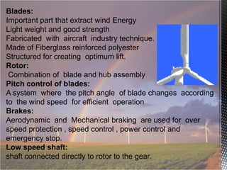
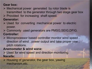
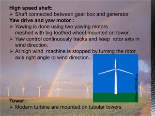
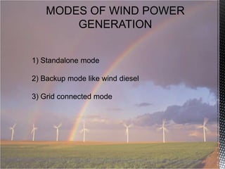
Downloaded 241 times

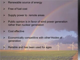

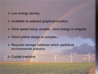

This document discusses the generation of wind energy, including historical developments, classifications of wind turbines, and various modes of power generation. It outlines the components of wind turbines, their design, operation, and the principles of aerodynamics involved in energy extraction. Moreover, it highlights advantages and challenges associated with wind energy, including its renewable nature, economic competitiveness, and irregular availability.