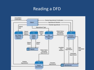
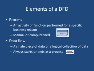
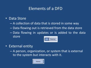
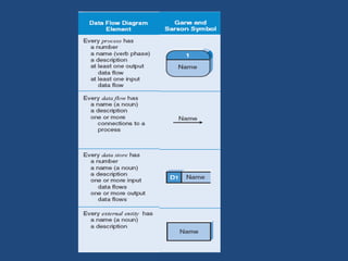
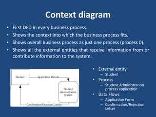
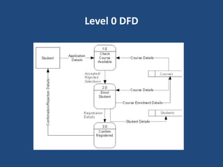
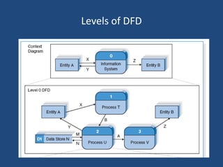
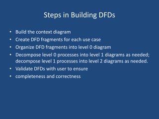
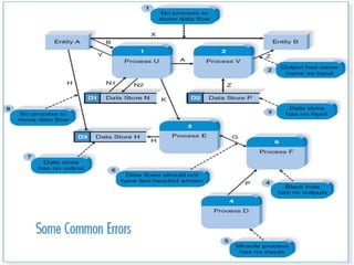
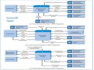
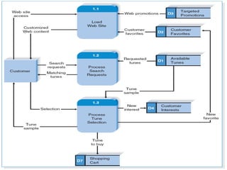
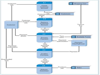
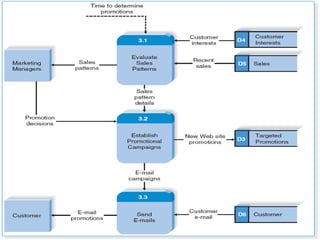
Data Flow Diagram (DFD) 
Prof. Sadique Nayeem
Reading a DFD
Elements of a DFD 
• Process 
– An activity or function performed for a specific 
business reason 
– Manual or computerized 
• Data flow 
– A single piece of data or a logical collection of data 
– Always starts or ends at a process
Elements of a DFD 
• Data Store 
– A collection of data that is stored in some way 
– Data flowing out is retrieved from the data store 
– Data flowing in updates or is added to the data 
store 
• External entity 
– A person, organization, or system that is external 
to the system but interacts with it.
Context diagram 
• First DFD in every business process. 
• Shows the context into which the business process fits. 
• Shows overall business process as just one process (process 0). 
• Shows all the external entities that receive information from or 
contribute information to the system. 
• External entity 
– Student 
• Process 
– Student Administration 
process application 
• Data Flows 
– Application Form 
– Confirmation/Rejection 
Letter
Level 0 Diagram 
• Shows all the major processes that comprise the overall 
system – the internal components of process 0 
• Shows how the major processes are interrelated by data flows 
• Shows external entities and the major processes with which 
they interact 
• Adds data stores
Level 0 DFD
Level 0 DFD 
• External entity 
– Student 
• Processes 
– Check available, Enroll student, Confirm Registration 
• Data Flows 
– Application Form, Course Details, Course Enrolment Details, 
Student Details, 
– Confirmation/Rejection Letter 
• Data Stores 
– Courses, Students
Levels of DFD
Level 1 Diagrams 
• Generally, one level 1 diagram is created for every major 
process on the level 0 diagram. 
• Shows all the internal processes that comprise a single 
process on the level 0 diagram. 
• Shows how information moves from and to each of these 
processes. 
• If a parent process is decomposed into, for example, three 
child processes, these three child processes wholly and 
completely make up the parent process.
Level 2 Diagrams 
• Shows all processes that comprise a single process on the 
level 1 diagram 
• Shows how information moves from and to each of these 
processes 
• Level 2 diagrams may not be needed for all level 1 processes 
• Correctly numbering each process helps the user understand 
where the process fits into the overall system
Steps in Building DFDs 
• Build the context diagram 
• Create DFD fragments for each use case 
• Organize DFD fragments into level 0 diagram 
• Decompose level 0 processes into level 1 diagrams as needed; 
decompose level 1 processes into level 2 diagrams as needed. 
• Validate DFDs with user to ensure 
• completeness and correctness
Reference 
• Systems Analysis Design, 5th edition, A. Dennis, B. A. Wixom and R. M. 
Roth, John Wiley and sons.

Data Flow Diagram (DFD)

  • 1.
    Data Flow Diagram(DFD) Prof. Sadique Nayeem
  • 2.
  • 3.
    Elements of aDFD • Process – An activity or function performed for a specific business reason – Manual or computerized • Data flow – A single piece of data or a logical collection of data – Always starts or ends at a process
  • 4.
    Elements of aDFD • Data Store – A collection of data that is stored in some way – Data flowing out is retrieved from the data store – Data flowing in updates or is added to the data store • External entity – A person, organization, or system that is external to the system but interacts with it.
  • 6.
    Context diagram •First DFD in every business process. • Shows the context into which the business process fits. • Shows overall business process as just one process (process 0). • Shows all the external entities that receive information from or contribute information to the system. • External entity – Student • Process – Student Administration process application • Data Flows – Application Form – Confirmation/Rejection Letter
  • 7.
    Level 0 Diagram • Shows all the major processes that comprise the overall system – the internal components of process 0 • Shows how the major processes are interrelated by data flows • Shows external entities and the major processes with which they interact • Adds data stores
  • 8.
  • 9.
    Level 0 DFD • External entity – Student • Processes – Check available, Enroll student, Confirm Registration • Data Flows – Application Form, Course Details, Course Enrolment Details, Student Details, – Confirmation/Rejection Letter • Data Stores – Courses, Students
  • 10.
  • 11.
    Level 1 Diagrams • Generally, one level 1 diagram is created for every major process on the level 0 diagram. • Shows all the internal processes that comprise a single process on the level 0 diagram. • Shows how information moves from and to each of these processes. • If a parent process is decomposed into, for example, three child processes, these three child processes wholly and completely make up the parent process.
  • 12.
    Level 2 Diagrams • Shows all processes that comprise a single process on the level 1 diagram • Shows how information moves from and to each of these processes • Level 2 diagrams may not be needed for all level 1 processes • Correctly numbering each process helps the user understand where the process fits into the overall system
  • 14.
    Steps in BuildingDFDs • Build the context diagram • Create DFD fragments for each use case • Organize DFD fragments into level 0 diagram • Decompose level 0 processes into level 1 diagrams as needed; decompose level 1 processes into level 2 diagrams as needed. • Validate DFDs with user to ensure • completeness and correctness
  • 21.
    Reference • SystemsAnalysis Design, 5th edition, A. Dennis, B. A. Wixom and R. M. Roth, John Wiley and sons.