Downloaded 245 times

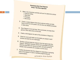
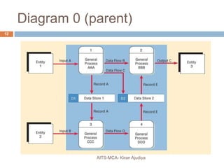
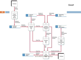

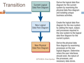
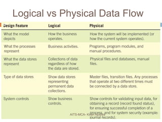
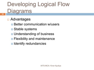
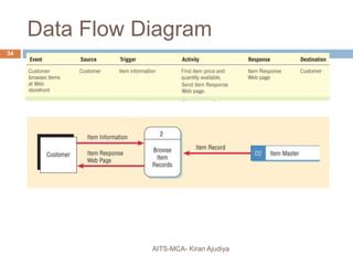


The document discusses the use of Data Flow Diagrams (DFDs) as a structured analysis technique for analyzing data-oriented systems, focusing on inputs, processes, and outputs. It emphasizes the advantages of DFDs, such as neutrality and user communication, while outlining conventions and best practices for creating effective DFDs, including context diagrams and nested child diagrams. Additionally, it addresses common errors in DFD creation and distinguishes between logical and physical data flows.