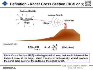
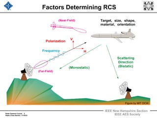
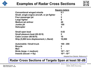
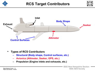
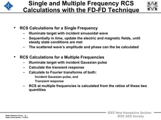
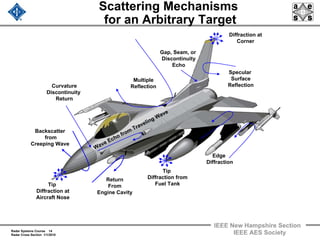
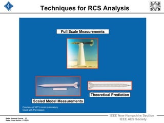
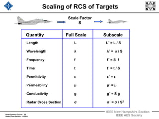
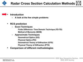
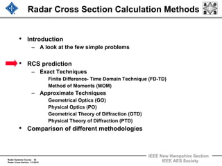
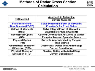
IEEE New Hampshire Section
Radar Systems Course 1
Radar Cross Section 1/1/2010 IEEE AES Society
Radar Systems Engineering
Lecture 7 – Part 1
Radar Cross Section
Dr. Robert M. O’Donnell
IEEE New Hampshire Section
Guest Lecturer
Radar Systems Course 2
Radar Cross Section 1/1/2010
IEEE New Hampshire Section
IEEE AES Society
Block Diagram of Radar System
Transmitter
Waveform
Generation
Power
Amplifier
T / R
Switch
Antenna
Propagation
Medium
Target
Radar
Cross
Section
Photo Image
Courtesy of US Air Force
Used with permission.
Pulse
Compression
Receiver
Clutter Rejection
(Doppler Filtering)
A / D
Converter
General Purpose Computer
Tracking
Data
Recording
Parameter
Estimation
Detection
Signal Processor Computer
Thresholding
User Displays and Radar Control
This lecture
Radar Systems Course 3
Radar Cross Section 1/1/2010
IEEE New Hampshire Section
IEEE AES Society
Definition - Radar Cross Section (RCS or σ)
Radar Cross Section (RCS) is the hypothetical area, that would intercept the
incident power at the target, which if scattered isotropically, would produce
the same echo power at the radar, as the actual target.
Figure by MIT OCW.
Radar Systems Course 4
Radar Cross Section 1/1/2010
IEEE New Hampshire Section
IEEE AES Society
Factors Determining RCS
Figure by MIT OCW.
Radar Systems Course 5
Radar Cross Section 1/1/2010
IEEE New Hampshire Section
IEEE AES Society
Threat’s View of the Radar
Range Equation
Transmitted Pulse
Received Pulse
Target Cross Section σ
Antenna Gain G
Transmit Power PT
Figure by MIT OCW.
Distance from Radar to Target
Radar Range Equation
R
S
N
=
Pt G2 λ2 σ
(4π)3 R4 k TS Bn L
Cannot Control
Can Control
Cannot Control
Radar Systems Course 6
Radar Cross Section 1/1/2010
IEEE New Hampshire Section
IEEE AES Society
Outline
• Radar cross section (RCS) of typical targets
– Variation with frequency, type of target, etc.
• Physical scattering mechanisms and contributors to
the RCS of a target
• Prediction of a target’s radar cross section
– Measurement
– Theoretical Calculation
Radar Systems Course 7
Radar Cross Section 1/1/2010
IEEE New Hampshire Section
IEEE AES Society
Radar Cross Section of Artillery Shell
M107 Shell
for
155mm Howitzer
Aspect Angle (degrees)
0 20 40 60 80 100 120 140 160 180
RadarCrossSection(dBsm)
0
-60
-20
-30
-40
-50
-10
Typical Artillery Shell
RCS vs. Aspect Angle of an Artillery Shell
Courtesy US Marine Corps
Radar Systems Course 8
Radar Cross Section 1/1/2010
IEEE New Hampshire Section
IEEE AES Society
Radar Cross Section of Cessna 150L
S Band
V V
Polarization
Measured at RATSCAT (6585th Test Group) Holloman AFB for FAA
Courtesy of Federal Aviation Administration
Aspect Angle (degrees)
0 90 180 270 360
RadarCrossSection(dBsm)
0
-20
20
40
Cessna 150L (in takeoff) Cessna 150L (in flight)
Scott Studio Photography with permissionScott Studio Photography with permission
Radar Systems Course 9
Radar Cross Section 1/1/2010
IEEE New Hampshire Section
IEEE AES Society
Aspect Angle Dependence of RCS
Cone Sphere Re-entry Vehicle (RV) Example
Figure by MIT OCW.
Radar Systems Course 10
Radar Cross Section 1/1/2010
IEEE New Hampshire Section
IEEE AES Society
Examples of Radar Cross Sections
Square meters
Conventional winged missile 0.1
Small, single engine aircraft, or jet fighter 1
Four passenger jet 2
Large fighter 6
Medium jet airliner 40
Jumbo jet 100
Helicopter 3
Small open boat 0.02
Small pleasure boat (20-30 ft) 2
Cabin cruiser (40-50 ft) 10
Ship (5,000 tons displacement, L Band) 10,000
Automobile / Small truck 100 - 200
Bicycle 2
Man 1
Birds (large -> medium) 10-2 - 10-3
Insects (locust -> fly) 10-4 - 10-5
Radar Cross Sections of Targets Span at least 50 dB
Adapted from Skolnik, Reference 2
Radar Systems Course 11
Radar Cross Section 1/1/2010
IEEE New Hampshire Section
IEEE AES Society
Outline
• Radar cross section (RCS) of typical targets
– Variation with frequency, type of target, etc.
• Physical scattering mechanisms and contributors to
the RCS of a target
• Prediction of a target’s radar cross section
– Measurement
– Theoretical Calculation
Radar Systems Course 12
Radar Cross Section 1/1/2010
IEEE New Hampshire Section
IEEE AES Society
RCS Target Contributors
• Types of RCS Contributors
– Structural (Body shape, Control surfaces, etc.)
– Avionics (Altimeter, Seeker, GPS, etc.)
– Propulsion (Engine inlets and exhausts, etc.)
Inlet
Control Surfaces
Altimeter
Seeker
Body Shape
Exhaust
Radar Systems Course 13
Radar Cross Section 1/1/2010
IEEE New Hampshire Section
IEEE AES Society
Single and Multiple Frequency RCS
Calculations with the FD-FD Technique
• RCS Calculations for a Single Frequency
– Illuminate target with incident sinusoidal wave
– Sequentially in time, update the electric and magnetic fields, until
steady state conditions are met
– The scattered wave’s amplitude and phase can the be calculated
• RCS Calculations for a Multiple Frequencies
– Illuminate target with incident Gaussian pulse
– Calculate the transient response
– Calculate to Fourier transforms of both:
Incident Gaussian pulse, and
Transient response
– RCS at multiple frequencies is calculated from the ratios of these two
quantities
Radar Systems Course 14
Radar Cross Section 1/1/2010
IEEE New Hampshire Section
IEEE AES Society
Scattering Mechanisms
for an Arbitrary Target
Tip
Diffraction at
Aircraft Nose
Diffraction at
Corner
Return
From
Engine Cavity
Edge
Diffraction
Tip
Diffraction from
Fuel Tank
Specular
Surface
Reflection
Multiple
Reflection
Wave Echo from
Traveling Wave
Gap, Seam, or
Discontinuity
Echo
Backscatter
from
Creeping Wave
Curvature
Discontinuity
Return
Radar Systems Course 15
Radar Cross Section 1/1/2010
IEEE New Hampshire Section
IEEE AES Society
Measured RCS of C-29 Aircraft Model
Full Scale C-29
BAE Hawker 125-800
Aspect Angle (degrees)
RCS(dBsm)
0 60 120 180 240 300 360
20
-20
-10
0
10
-30
1/12 Scale
Model
Measurement
X-Band
HH Polarization
Waterline Cut
Wing Leading
Edge
Fuselage
Specular
Courtesy of Arpingstone
Adapted from Atkins, Reference 5
Courtesy of MIT Lincoln Laboratory
Radar Systems Course 16
Radar Cross Section 1/1/2010
IEEE New Hampshire Section
IEEE AES Society
Outline
• Radar cross section (RCS) of typical targets
– Variation with frequency, type of target, etc.
• Physical scattering mechanisms and contributors to
the RCS of a target
• Prediction of a target’s radar cross section
– Measurement
– Theoretical Calculation
Radar Systems Course 17
Radar Cross Section 1/1/2010
IEEE New Hampshire Section
IEEE AES Society
Techniques for RCS Analysis
Scaled Model Measurements
Theoretical Prediction
Full Scale Measurements
Courtesy of MIT Lincoln Laboratory
Used with Permission
Radar Systems Course 18
Radar Cross Section 1/1/2010
IEEE New Hampshire Section
IEEE AES Society
Full Scale Measurements
Target on Support
• Foam column mounting
– Dielectric properties of Styrofoam close to those of free space
• Metal pylon mounting
– Metal pylon shaped to reduce radar reflections
– Background subtraction can be used
Derived from: http://www.af.mil/shared/media/photodb/photos/050805-F-0000S-003.jpg
Courtesy of MIT Lincoln Laboratory
Used with Permission
Radar Systems Course 19
Radar Cross Section 1/1/2010
IEEE New Hampshire Section
IEEE AES Society
Full Scale Measurement of
Johnson Generic Aircraft Model (JGAM)
RATSCAT Outdoor Measurement
Facility at Holloman AFB
Courtesy of MIT Lincoln Laboratory
Used with Permission
Radar Systems Course 20
Radar Cross Section 1/1/2010
IEEE New Hampshire Section
IEEE AES Society
Compact Range RCS Measurement
Radar Reflectivity Laboratory (Pt. Mugu) / AFRL Compact Range (WPAFB)
Courtesy of U. S. Navy.
Target
Main
Reflector
Feed
Antenna
Plane
Wave
Low RCS
Pylon
Sub-Reflector
Radar Systems Course 21
Radar Cross Section 1/1/2010
IEEE New Hampshire Section
IEEE AES Society
Scale Model Measurement
Subscale
Measure at frequency S x F
Scale Factor
S
(Reduced Size)
Full Scale
Measure at frequency f
MQM-107 Drone in 0.29, 0.034, and 0.01 scaled sizes
Courtesy of MIT Lincoln Laboratory
Used with Permission
Radar Systems Course 22
Radar Cross Section 1/1/2010
IEEE New Hampshire Section
IEEE AES Society
Scaling of RCS of Targets
Scale Factor
S
Length L L´ = L / S
Wavelength λ λ´ = λ / S
Frequency f f´ = S f
Time t t´ = t / S
Permittivity ε ε´ = ε
Permeability μ μ´ = μ
Conductivity g g´ = S g
Radar Cross Section σ σ´ = σ / S2
Quantity Full Scale Subscale
Radar Systems Course 23
Radar Cross Section 1/1/2010
IEEE New Hampshire Section
IEEE AES Society
Outline
• Radar cross section (RCS) of typical targets
– Variation with frequency, type of target, etc.
• Physical scattering mechanisms and contributors to
the RCS of a target
• Prediction of a target’s radar cross section
– Measurement
– Theoretical Calculation
Radar Systems Course 24
Radar Cross Section 1/1/2010
IEEE New Hampshire Section
IEEE AES Society
Radar Cross Section Calculation Methods
• Introduction
– A look at the few simple problems
• RCS prediction
– Exact Techniques
Finite Difference- Time Domain Technique (FD-TD)
Method of Moments (MOM)
– Approximate Techniques
Geometrical Optics (GO)
Physical Optics (PO)
Geometrical Theory of Diffraction (GTD)
Physical Theory of Diffraction (PTD)
• Comparison of different methodologies
Radar Systems Course 25
Radar Cross Section 1/1/2010
IEEE New Hampshire Section
IEEE AES Society
Radar Cross Section of Sphere
Rayleigh Region
λ >> a
σ = k / λ4
Mie or Resonance
Region
Oscillations
Backscattered
wave interferes
with creeping wave
Optical Region
λ << a
σ = π a2
Surface and edge
scattering occur
Circumference/ wavelength = 2πa / λ
RadarCrossSection/πa2
10
1
10-3
10-2
10-1
0.1 0.2 0.4 0.7 1 2 4 7 10 20
Rayleigh
Region
Resonance or Mie
Region
Optical
Region
a
Higher Wavelengths Lower Wavelengths
Figure by MIT OCW.
λ >> a
λ << a
Radar Systems Course 26
Radar Cross Section 1/1/2010
IEEE New Hampshire Section
IEEE AES Society
Radar Cross Section Calculation Issues
• Three regions of wavelength
Rayleigh (λ >> a)
Mie / Resonance (λ ~ a)
Optical (λ << a)
• Other simple shapes
– Examples: Cylinders, Flat Plates, Rods, Cones, Ogives
– Some amenable to relatively straightforward solutions in some
wavelength regions
• Complex targets:
– Examples: Aircraft, Missiles, Ships)
– RCS changes significantly with very small changes in frequency
and / or viewing angle
See Ref. 6 (Levanon), problem 2-1 or Ref. 2 (Skolnik) page 57
• We will spend the rest of the lecture studying the different
basic methods of calculating radar cross sections
Radar Systems Course 27
Radar Cross Section 1/1/2010
IEEE New Hampshire Section
IEEE AES Society
High Frequency RCS Approximations
(Simple Scattering Features)
Scattering Feature Orientation Approximate RCS
Corner Reflector Axis of symmetry along LOS
Flat Plate Surface perpendicular to LOS
Singly Curved Surface Surface perpendicular to LOS
Doubly Curved Surface Surface perpendicular to LOS
Straight Edge Edge perpendicular to LOS
Curved Edge Edge element perpendicular to LOS
Cone Tip Axial incidence
Where:
22
eff /A4 λπ
22
/A4 λπ
22
/A4 λπ
21 aaπ
πλ /2
2/a λ
)2/(sin42
αλ
Adapted from Knott is Skolnik Reference 3
Radar Systems Course 28
Radar Cross Section 1/1/2010
IEEE New Hampshire Section
IEEE AES Society
Radar Cross Section Calculation Issues
• Three regions of wavelength
Rayleigh (λ >> a)
Mie / Resonance (λ ~ a)
Optical (λ << a)
• Other simple shapes
– Examples: Cylinders, Flat Plates, Rods, Cones, Ogives
– Some amenable to relatively straightforward solutions in some
wavelength regions
• Complex targets:
– Examples: Aircraft, Missiles, Ships)
– RCS changes significantly with very small changes in frequency
and / or viewing angle
See Ref. 6 (Levanon), problem 2-1 or Ref. 2 (Skolnik) page 57
• We will spend the rest of the lecture studying the different
basic methods of calculating radar cross sections
Radar Systems Course 29
Radar Cross Section 1/1/2010
IEEE New Hampshire Section
IEEE AES Society
RCS Calculation - Overview
• Electromagnetism Problem
– A plane wave with electric field, , impinges on the target of
interest and some of the energy scatters back to the radar
antenna
– Since, the radar cross section is given by:
– All we need to do is use Maxwell’s Equations to calculate the
scattered electric field
– That’s easier said that done
– Before we examine in detail these different techniques, let’s
review briefly the necessary electromagnetism concepts and
formulae, in the next few viewgraphs
IE
r
2
I
2
S2
r
E
E
r4lim r
r
π=σ
∞→
SE
r
Radar Systems Course 30
Radar Cross Section 1/1/2010
IEEE New Hampshire Section
IEEE AES Society
Maxwell’s Equations
• Source free region of space:
• Free space constitutive relations:
0)t,r(B
0)t,r(D
t
)t,r(D
)t,r(H
t
)t,r(B
)t,r(E
=⋅∇
=⋅∇
∂
∂
=×∇
∂
∂
−=×∇
→
→
rr
rr
rr
rr
rr
rr
)t,r(H)t,r(B
)t,r(E)t,r(D
o
o
rrrr
rrrr
μ=
ε= = Free space permittivity
= Free space permeability
oε
oμ
Radar Systems Course 31
Radar Cross Section 1/1/2010
IEEE New Hampshire Section
IEEE AES Society
Maxwell’s Equations in Time-Harmonic Form
• Source free region:
• Time dependence
0)r(B
0)r(D
)r(Di)r(H
)r(Bi)r(E
=⋅∇
=⋅∇
ω−=×∇
ω=×∇
→
→
rr
rr
rrrr
rrrr
{ }
{ }ti
ti
e)r(HRe)t,r(H
e)r(ERe)t,r(E
ω−
ω−
=
=
rrrr
rrrr
Radar Systems Course 32
Radar Cross Section 1/1/2010
IEEE New Hampshire Section
IEEE AES Society
Boundary Conditions
• Tangential components of and are continuous:
• For surfaces that are perfect conductors:
• Radiation condition:
– As
E
r
H
r
21
21
HxnˆHxnˆ
ExnˆExnˆ
rr
rr
=
=
0Exnˆ =
r
r
1
)r(Er ∝∞→
rr
2222
1111
HE
HE
rr
rr
εμ
εμ nˆ
Surface
BoundaryMedium 1
Medium 2
Radar Systems Course 33
Radar Cross Section 1/1/2010
IEEE New Hampshire Section
IEEE AES Society
Scattering Matrix
• For a linear polarization basis
• The incident field polarization is related to the scattered field
polarization by this Scattering Matrix - S
• For and a reciprocal medium and for monostatic radar cross
section:
• For a circular polarization basis
⎥
⎦
⎤
⎢
⎣
⎡
⎥
⎦
⎤
⎢
⎣
⎡
=⎥
⎦
⎤
⎢
⎣
⎡
=
HI
VI
HHHV
VHVV
ikr
HS
VS
S
E
E
SS
SS
r
e
E
E
E
r
2
VHVH
2
HHHH
2
VVVV
S4
S4
S4
π=σ
π=σ
π=σ
RLLLRR ,, σσσ
HVVH σ=σ
Scattering Matrix - S
Radar Systems Course 34
Radar Cross Section 1/1/2010
IEEE New Hampshire Section
IEEE AES Society
Radar Cross Section Calculation Methods
• Introduction
– A look at the few simple problems
• RCS prediction
– Exact Techniques
Finite Difference- Time Domain Technique (FD-TD)
Method of Moments (MOM)
– Approximate Techniques
Geometrical Optics (GO)
Physical Optics (PO)
Geometrical Theory of Diffraction (GTD)
Physical Theory of Diffraction (PTD)
• Comparison of different methodologies
Radar Systems Course 35
Radar Cross Section 1/1/2010
IEEE New Hampshire Section
IEEE AES Society
Methods of Radar Cross Section
Calculation
RCS Method
Approach to Determine
Surface Currents
Finite Difference-
Time Domain (FD-TD)
Solve Differential Form of Maxwell’s
Equation’s for Exact Fields
Method of Moments
(MoM)
Solve Integral Form of Maxwell’s
Equation’s for Exact Currents
Geometrical Optics
(GO)
Current Contribution Assumed to Vanish
Except at Isolated Specular Points
Physical Optics
(PO)
Currents Approximated by Tangent
Plane Method
Geometrical Theory of
Diffraction (GTD)
Geometrical Optics with Added Edge
Current Contribution
Physical Theory of
Diffraction (PTD)
Physical Optics with Added Edge
Current Contribution
Radar Systems Course 36
Radar Cross Section 1/1/2010
IEEE New Hampshire Section
IEEE AES Society
Finite Difference- Time Domain (FD-TD)
Overview
• Exact method for calculation radar cross section
• Solve differential form of Maxwell’s equations
– The change in the E field, in time, is dependent on the change in the H
field, across space, and visa versa
• The differential equations are transformed to difference equations
– These difference equations are used to sequentially calculate the E
field at one time and the use those E field calculations to calculate H
field at an incrementally greater time; etc. etc.
Called “Marching in Time”
• These time stepped E and H field calculations avoid the necessity
of solving simultaneous equations
• Good approach for structures with varying electric and magnetic
properties and for cavities
Radar Systems Course 37
Radar Cross Section 1/1/2010
IEEE New Hampshire Section
IEEE AES Society
Maxwell’s Equations in
Rectangular Coordinates
• Examine 2 D problem – no dependence:
• Equations decouple into H-field polarization and E-field
polarization
ZoXY
YoZX
XoYZ
E
t
H
y
H
x
H
t
E
x
E
z
E
t
H
z
H
y
∂
∂
ε=
∂
∂
−
∂
∂
∂
∂
μ−=
∂
∂
−
∂
∂
∂
∂
ε=
∂
∂
−
∂
∂
ZoXY
YoZX
XoYZ
H
t
E
y
E
x
E
t
H
x
H
z
H
t
E
z
E
y
∂
∂
μ−=
∂
∂
−
∂
∂
∂
∂
ε=
∂
∂
−
∂
∂
∂
∂
μ−=
∂
∂
−
∂
∂
0
y
=
∂
∂
• H-field polarization • E-field polarization
ZXY EEH ZXY HHE
y
Radar Systems Course 38
Radar Cross Section 1/1/2010
IEEE New Hampshire Section
IEEE AES Society
Maxwell’s Equations in
Rectangular Coordinates
• Examine 2 D problem – no dependence:
• Equations decouple into H-field polarization and E-field
polarization
0
y
=
∂
∂
• H-field polarization
ZXY EEH
• E-field polarization
ZXY HHE
ZoXY
YoZX
XoYZ
E
t
H
y
H
x
H
t
E
x
E
z
E
t
H
z
H
y
∂
∂
ε=
∂
∂
−
∂
∂
∂
∂
μ−=
∂
∂
−
∂
∂
∂
∂
ε=
∂
∂
−
∂
∂
ZoXY
YoZX
XoYZ
H
t
E
y
E
x
E
t
H
x
H
z
H
t
E
z
E
y
∂
∂
μ−=
∂
∂
−
∂
∂
∂
∂
ε=
∂
∂
−
∂
∂
∂
∂
μ−=
∂
∂
−
∂
∂
= 0
= 0
= 0
= 0
y
Radar Systems Course 39
Radar Cross Section 1/1/2010
IEEE New Hampshire Section
IEEE AES Society
• H-field polarization:
• Discrete form:
• Electric and magnetic fields are calculated alternately by the
marching in time method
Discrete Form of Maxwell’s Equations
( ) ( )
( )t,y,xE
x
t,y,xE
z
t,y,xH
t
Z
XYo
∂
∂
−
∂
∂
=
∂
∂
μ−
⎥
⎦
⎤
⎢
⎣
⎡
⎟
⎠
⎞
⎜
⎝
⎛ Δ
+−⎟
⎠
⎞
⎜
⎝
⎛ Δ
+Δ+
Δ
−
⎥
⎦
⎤
⎢
⎣
⎡
⎟
⎠
⎞
⎜
⎝
⎛ Δ
+−⎟
⎠
⎞
⎜
⎝
⎛
Δ+
Δ
+
Δ
=
⎥
⎦
⎤
⎢
⎣
⎡
⎟
⎠
⎞
⎜
⎝
⎛ Δ
−
Δ
+
Δ
+−⎟
⎠
⎞
⎜
⎝
⎛ Δ
+
Δ
+
Δ
+
Δ
μ
−
o
Z
ooZo
Z
oXoZ
X
oo
X
oXoZo
X
oX
Z
T
o
Z
o
X
oY
T
o
Z
o
X
oY
T
o
t,
2
z,xEt,
2
z,xE
1
t,z,
2
xEt,z,
2
xE
1
2
t,
2
z,
2
xH
2
t,
2
z,
2
xH
z
xy
Ex
EZ
HY Yee’s
Lattice
(2-D)
Radar Systems Course 40
Radar Cross Section 1/1/2010
IEEE New Hampshire Section
IEEE AES Society
FD-TD Calculations and Absorbing
Boundary Conditions (ABC)
• Absorbing Boundary Condition (ABC) Used to Limit Computational Domain
– Reflections at exterior boundary are minimized
– Traditional ABC’s model field as outgoing wave to estimate field quantities outside
domain
– More recent perfectly matched layer (PML) model uses non-physical layer, that
absorbs waves
Ex
EZ
HY
Perfect ConductorLayer Perfectly Matched
0H
x2
1
tc
1
txc
1
y2
2
2
2
2
2
=⎟⎟
⎠
⎞
⎜⎜
⎝
⎛
∂
∂
−
∂
∂
+
∂∂
∂
2nd Order ABC
1st Order ABC 0H
tc
1
xz2
1
y =⎟
⎟
⎠
⎞
⎜
⎜
⎝
⎛
∂
∂
+⎟⎟
⎠
⎞
⎜⎜
⎝
⎛
∂
∂
+
∂
∂
Total Field
Target
Domain of Computation
Absorbing Boundary
0ETAN =
Scattered Field
Radar Systems Course 41
Radar Cross Section 1/1/2010
IEEE New Hampshire Section
IEEE AES Society
RCS Calculations Using the FD-TD Method
• Single frequency RCS calculations
– Excite with sinusoidal incident wave
– Run computation until steady state is reached
– Calculate amplitude and phase of scattered wave
• Multiple frequency RCS calculations
– Excite with Gaussian pulse incident wave
– Calculate transient response
– Take Fourier transform of incident pulse and transient
response
– Calculate ratios of these transforms to obtain RCS at multiple
frequencies
From Atkins, Reference 5
Courtesy of MIT Lincoln Laboratory
Radar Systems Course 42
Radar Cross Section 1/1/2010
IEEE New Hampshire Section
IEEE AES Society
Description of Scattering Cases on Video
Finite Difference Time Domain (FDTD) Simulations
Ei Hi
Hi
Ei
15 deg 15 deg
Hi
Ei
Case 1 – Plate I Case 2 – Plate II Case 3 – Plate III
Case 4 – Cylinder I Case 5 – Cylinder II Case 6 – Cavity
Hi
Ei
Hi
EiEi Hi
Courtesy of MIT Lincoln Laboratory Used with Permission
Radar Systems Course 43
Radar Cross Section 1/1/2010
IEEE New Hampshire Section
IEEE AES Society
FD-TD Simulation of Scattering by Strip
0.5 m
Ey
4 m
• Gaussian pulse plane wave incidence
• E-field polarization (Ey plotted)
• Phenomena: specular reflection
Case 1
Courtesy of
MIT Lincoln Laboratory
Used with Permission
Radar Systems Course 44
Radar Cross Section 1/1/2010
IEEE New Hampshire Section
IEEE AES Society
Case 1
Courtesy of
MIT Lincoln Laboratory
Used with Permission
Radar Systems Course 45
Radar Cross Section 1/1/2010
IEEE New Hampshire Section
IEEE AES Society
FD-TD Simulation of Scattering by Strip
Case 1
Courtesy of
MIT Lincoln Laboratory
Used with Permission
Radar Systems Course 46
Radar Cross Section 1/1/2010
IEEE New Hampshire Section
IEEE AES Society
FD-TD Simulation of Scattering by Cylinder
0.5 m
Hy
2 m
• Gaussian pulse plane wave incidence
• H-field polarization (Hy plotted)
• Phenomena: creeping waveCase 5
Courtesy of
MIT Lincoln Laboratory
Used with Permission
Radar Systems Course 47
Radar Cross Section 1/1/2010
IEEE New Hampshire Section
IEEE AES Society
Case 5
Courtesy of
MIT Lincoln Laboratory
Used with Permission
Radar Systems Course 48
Radar Cross Section 1/1/2010
IEEE New Hampshire Section
IEEE AES Society
FD-TD Simulation of Scattering by Cylinder
Case 5
Courtesy of
MIT Lincoln Laboratory
Used with Permission
Radar Systems Course 49
Radar Cross Section 1/1/2010
IEEE New Hampshire Section
IEEE AES Society
Backscatter of Short Pulse from Sphere
Creeping Wave Return
Specular
Return
Radius of sphere is equal
to the radar wavelength
Figure by MIT OCW.

Radar 2009 a 7 radar cross section 1

  • 1.
    IEEE New HampshireSection Radar Systems Course 1 Radar Cross Section 1/1/2010 IEEE AES Society Radar Systems Engineering Lecture 7 – Part 1 Radar Cross Section Dr. Robert M. O’Donnell IEEE New Hampshire Section Guest Lecturer
  • 2.
    Radar Systems Course2 Radar Cross Section 1/1/2010 IEEE New Hampshire Section IEEE AES Society Block Diagram of Radar System Transmitter Waveform Generation Power Amplifier T / R Switch Antenna Propagation Medium Target Radar Cross Section Photo Image Courtesy of US Air Force Used with permission. Pulse Compression Receiver Clutter Rejection (Doppler Filtering) A / D Converter General Purpose Computer Tracking Data Recording Parameter Estimation Detection Signal Processor Computer Thresholding User Displays and Radar Control This lecture
  • 3.
    Radar Systems Course3 Radar Cross Section 1/1/2010 IEEE New Hampshire Section IEEE AES Society Definition - Radar Cross Section (RCS or σ) Radar Cross Section (RCS) is the hypothetical area, that would intercept the incident power at the target, which if scattered isotropically, would produce the same echo power at the radar, as the actual target. Figure by MIT OCW.
  • 4.
    Radar Systems Course4 Radar Cross Section 1/1/2010 IEEE New Hampshire Section IEEE AES Society Factors Determining RCS Figure by MIT OCW.
  • 5.
    Radar Systems Course5 Radar Cross Section 1/1/2010 IEEE New Hampshire Section IEEE AES Society Threat’s View of the Radar Range Equation Transmitted Pulse Received Pulse Target Cross Section σ Antenna Gain G Transmit Power PT Figure by MIT OCW. Distance from Radar to Target Radar Range Equation R S N = Pt G2 λ2 σ (4π)3 R4 k TS Bn L Cannot Control Can Control Cannot Control
  • 6.
    Radar Systems Course6 Radar Cross Section 1/1/2010 IEEE New Hampshire Section IEEE AES Society Outline • Radar cross section (RCS) of typical targets – Variation with frequency, type of target, etc. • Physical scattering mechanisms and contributors to the RCS of a target • Prediction of a target’s radar cross section – Measurement – Theoretical Calculation
  • 7.
    Radar Systems Course7 Radar Cross Section 1/1/2010 IEEE New Hampshire Section IEEE AES Society Radar Cross Section of Artillery Shell M107 Shell for 155mm Howitzer Aspect Angle (degrees) 0 20 40 60 80 100 120 140 160 180 RadarCrossSection(dBsm) 0 -60 -20 -30 -40 -50 -10 Typical Artillery Shell RCS vs. Aspect Angle of an Artillery Shell Courtesy US Marine Corps
  • 8.
    Radar Systems Course8 Radar Cross Section 1/1/2010 IEEE New Hampshire Section IEEE AES Society Radar Cross Section of Cessna 150L S Band V V Polarization Measured at RATSCAT (6585th Test Group) Holloman AFB for FAA Courtesy of Federal Aviation Administration Aspect Angle (degrees) 0 90 180 270 360 RadarCrossSection(dBsm) 0 -20 20 40 Cessna 150L (in takeoff) Cessna 150L (in flight) Scott Studio Photography with permissionScott Studio Photography with permission
  • 9.
    Radar Systems Course9 Radar Cross Section 1/1/2010 IEEE New Hampshire Section IEEE AES Society Aspect Angle Dependence of RCS Cone Sphere Re-entry Vehicle (RV) Example Figure by MIT OCW.
  • 10.
    Radar Systems Course10 Radar Cross Section 1/1/2010 IEEE New Hampshire Section IEEE AES Society Examples of Radar Cross Sections Square meters Conventional winged missile 0.1 Small, single engine aircraft, or jet fighter 1 Four passenger jet 2 Large fighter 6 Medium jet airliner 40 Jumbo jet 100 Helicopter 3 Small open boat 0.02 Small pleasure boat (20-30 ft) 2 Cabin cruiser (40-50 ft) 10 Ship (5,000 tons displacement, L Band) 10,000 Automobile / Small truck 100 - 200 Bicycle 2 Man 1 Birds (large -> medium) 10-2 - 10-3 Insects (locust -> fly) 10-4 - 10-5 Radar Cross Sections of Targets Span at least 50 dB Adapted from Skolnik, Reference 2
  • 11.
    Radar Systems Course11 Radar Cross Section 1/1/2010 IEEE New Hampshire Section IEEE AES Society Outline • Radar cross section (RCS) of typical targets – Variation with frequency, type of target, etc. • Physical scattering mechanisms and contributors to the RCS of a target • Prediction of a target’s radar cross section – Measurement – Theoretical Calculation
  • 12.
    Radar Systems Course12 Radar Cross Section 1/1/2010 IEEE New Hampshire Section IEEE AES Society RCS Target Contributors • Types of RCS Contributors – Structural (Body shape, Control surfaces, etc.) – Avionics (Altimeter, Seeker, GPS, etc.) – Propulsion (Engine inlets and exhausts, etc.) Inlet Control Surfaces Altimeter Seeker Body Shape Exhaust
  • 13.
    Radar Systems Course13 Radar Cross Section 1/1/2010 IEEE New Hampshire Section IEEE AES Society Single and Multiple Frequency RCS Calculations with the FD-FD Technique • RCS Calculations for a Single Frequency – Illuminate target with incident sinusoidal wave – Sequentially in time, update the electric and magnetic fields, until steady state conditions are met – The scattered wave’s amplitude and phase can the be calculated • RCS Calculations for a Multiple Frequencies – Illuminate target with incident Gaussian pulse – Calculate the transient response – Calculate to Fourier transforms of both: Incident Gaussian pulse, and Transient response – RCS at multiple frequencies is calculated from the ratios of these two quantities
  • 14.
    Radar Systems Course14 Radar Cross Section 1/1/2010 IEEE New Hampshire Section IEEE AES Society Scattering Mechanisms for an Arbitrary Target Tip Diffraction at Aircraft Nose Diffraction at Corner Return From Engine Cavity Edge Diffraction Tip Diffraction from Fuel Tank Specular Surface Reflection Multiple Reflection Wave Echo from Traveling Wave Gap, Seam, or Discontinuity Echo Backscatter from Creeping Wave Curvature Discontinuity Return
  • 15.
    Radar Systems Course15 Radar Cross Section 1/1/2010 IEEE New Hampshire Section IEEE AES Society Measured RCS of C-29 Aircraft Model Full Scale C-29 BAE Hawker 125-800 Aspect Angle (degrees) RCS(dBsm) 0 60 120 180 240 300 360 20 -20 -10 0 10 -30 1/12 Scale Model Measurement X-Band HH Polarization Waterline Cut Wing Leading Edge Fuselage Specular Courtesy of Arpingstone Adapted from Atkins, Reference 5 Courtesy of MIT Lincoln Laboratory
  • 16.
    Radar Systems Course16 Radar Cross Section 1/1/2010 IEEE New Hampshire Section IEEE AES Society Outline • Radar cross section (RCS) of typical targets – Variation with frequency, type of target, etc. • Physical scattering mechanisms and contributors to the RCS of a target • Prediction of a target’s radar cross section – Measurement – Theoretical Calculation
  • 17.
    Radar Systems Course17 Radar Cross Section 1/1/2010 IEEE New Hampshire Section IEEE AES Society Techniques for RCS Analysis Scaled Model Measurements Theoretical Prediction Full Scale Measurements Courtesy of MIT Lincoln Laboratory Used with Permission
  • 18.
    Radar Systems Course18 Radar Cross Section 1/1/2010 IEEE New Hampshire Section IEEE AES Society Full Scale Measurements Target on Support • Foam column mounting – Dielectric properties of Styrofoam close to those of free space • Metal pylon mounting – Metal pylon shaped to reduce radar reflections – Background subtraction can be used Derived from: http://www.af.mil/shared/media/photodb/photos/050805-F-0000S-003.jpg Courtesy of MIT Lincoln Laboratory Used with Permission
  • 19.
    Radar Systems Course19 Radar Cross Section 1/1/2010 IEEE New Hampshire Section IEEE AES Society Full Scale Measurement of Johnson Generic Aircraft Model (JGAM) RATSCAT Outdoor Measurement Facility at Holloman AFB Courtesy of MIT Lincoln Laboratory Used with Permission
  • 20.
    Radar Systems Course20 Radar Cross Section 1/1/2010 IEEE New Hampshire Section IEEE AES Society Compact Range RCS Measurement Radar Reflectivity Laboratory (Pt. Mugu) / AFRL Compact Range (WPAFB) Courtesy of U. S. Navy. Target Main Reflector Feed Antenna Plane Wave Low RCS Pylon Sub-Reflector
  • 21.
    Radar Systems Course21 Radar Cross Section 1/1/2010 IEEE New Hampshire Section IEEE AES Society Scale Model Measurement Subscale Measure at frequency S x F Scale Factor S (Reduced Size) Full Scale Measure at frequency f MQM-107 Drone in 0.29, 0.034, and 0.01 scaled sizes Courtesy of MIT Lincoln Laboratory Used with Permission
  • 22.
    Radar Systems Course22 Radar Cross Section 1/1/2010 IEEE New Hampshire Section IEEE AES Society Scaling of RCS of Targets Scale Factor S Length L L´ = L / S Wavelength λ λ´ = λ / S Frequency f f´ = S f Time t t´ = t / S Permittivity ε ε´ = ε Permeability μ μ´ = μ Conductivity g g´ = S g Radar Cross Section σ σ´ = σ / S2 Quantity Full Scale Subscale
  • 23.
    Radar Systems Course23 Radar Cross Section 1/1/2010 IEEE New Hampshire Section IEEE AES Society Outline • Radar cross section (RCS) of typical targets – Variation with frequency, type of target, etc. • Physical scattering mechanisms and contributors to the RCS of a target • Prediction of a target’s radar cross section – Measurement – Theoretical Calculation
  • 24.
    Radar Systems Course24 Radar Cross Section 1/1/2010 IEEE New Hampshire Section IEEE AES Society Radar Cross Section Calculation Methods • Introduction – A look at the few simple problems • RCS prediction – Exact Techniques Finite Difference- Time Domain Technique (FD-TD) Method of Moments (MOM) – Approximate Techniques Geometrical Optics (GO) Physical Optics (PO) Geometrical Theory of Diffraction (GTD) Physical Theory of Diffraction (PTD) • Comparison of different methodologies
  • 25.
    Radar Systems Course25 Radar Cross Section 1/1/2010 IEEE New Hampshire Section IEEE AES Society Radar Cross Section of Sphere Rayleigh Region λ >> a σ = k / λ4 Mie or Resonance Region Oscillations Backscattered wave interferes with creeping wave Optical Region λ << a σ = π a2 Surface and edge scattering occur Circumference/ wavelength = 2πa / λ RadarCrossSection/πa2 10 1 10-3 10-2 10-1 0.1 0.2 0.4 0.7 1 2 4 7 10 20 Rayleigh Region Resonance or Mie Region Optical Region a Higher Wavelengths Lower Wavelengths Figure by MIT OCW. λ >> a λ << a
  • 26.
    Radar Systems Course26 Radar Cross Section 1/1/2010 IEEE New Hampshire Section IEEE AES Society Radar Cross Section Calculation Issues • Three regions of wavelength Rayleigh (λ >> a) Mie / Resonance (λ ~ a) Optical (λ << a) • Other simple shapes – Examples: Cylinders, Flat Plates, Rods, Cones, Ogives – Some amenable to relatively straightforward solutions in some wavelength regions • Complex targets: – Examples: Aircraft, Missiles, Ships) – RCS changes significantly with very small changes in frequency and / or viewing angle See Ref. 6 (Levanon), problem 2-1 or Ref. 2 (Skolnik) page 57 • We will spend the rest of the lecture studying the different basic methods of calculating radar cross sections
  • 27.
    Radar Systems Course27 Radar Cross Section 1/1/2010 IEEE New Hampshire Section IEEE AES Society High Frequency RCS Approximations (Simple Scattering Features) Scattering Feature Orientation Approximate RCS Corner Reflector Axis of symmetry along LOS Flat Plate Surface perpendicular to LOS Singly Curved Surface Surface perpendicular to LOS Doubly Curved Surface Surface perpendicular to LOS Straight Edge Edge perpendicular to LOS Curved Edge Edge element perpendicular to LOS Cone Tip Axial incidence Where: 22 eff /A4 λπ 22 /A4 λπ 22 /A4 λπ 21 aaπ πλ /2 2/a λ )2/(sin42 αλ Adapted from Knott is Skolnik Reference 3
  • 28.
    Radar Systems Course28 Radar Cross Section 1/1/2010 IEEE New Hampshire Section IEEE AES Society Radar Cross Section Calculation Issues • Three regions of wavelength Rayleigh (λ >> a) Mie / Resonance (λ ~ a) Optical (λ << a) • Other simple shapes – Examples: Cylinders, Flat Plates, Rods, Cones, Ogives – Some amenable to relatively straightforward solutions in some wavelength regions • Complex targets: – Examples: Aircraft, Missiles, Ships) – RCS changes significantly with very small changes in frequency and / or viewing angle See Ref. 6 (Levanon), problem 2-1 or Ref. 2 (Skolnik) page 57 • We will spend the rest of the lecture studying the different basic methods of calculating radar cross sections
  • 29.
    Radar Systems Course29 Radar Cross Section 1/1/2010 IEEE New Hampshire Section IEEE AES Society RCS Calculation - Overview • Electromagnetism Problem – A plane wave with electric field, , impinges on the target of interest and some of the energy scatters back to the radar antenna – Since, the radar cross section is given by: – All we need to do is use Maxwell’s Equations to calculate the scattered electric field – That’s easier said that done – Before we examine in detail these different techniques, let’s review briefly the necessary electromagnetism concepts and formulae, in the next few viewgraphs IE r 2 I 2 S2 r E E r4lim r r π=σ ∞→ SE r
  • 30.
    Radar Systems Course30 Radar Cross Section 1/1/2010 IEEE New Hampshire Section IEEE AES Society Maxwell’s Equations • Source free region of space: • Free space constitutive relations: 0)t,r(B 0)t,r(D t )t,r(D )t,r(H t )t,r(B )t,r(E =⋅∇ =⋅∇ ∂ ∂ =×∇ ∂ ∂ −=×∇ → → rr rr rr rr rr rr )t,r(H)t,r(B )t,r(E)t,r(D o o rrrr rrrr μ= ε= = Free space permittivity = Free space permeability oε oμ
  • 31.
    Radar Systems Course31 Radar Cross Section 1/1/2010 IEEE New Hampshire Section IEEE AES Society Maxwell’s Equations in Time-Harmonic Form • Source free region: • Time dependence 0)r(B 0)r(D )r(Di)r(H )r(Bi)r(E =⋅∇ =⋅∇ ω−=×∇ ω=×∇ → → rr rr rrrr rrrr { } { }ti ti e)r(HRe)t,r(H e)r(ERe)t,r(E ω− ω− = = rrrr rrrr
  • 32.
    Radar Systems Course32 Radar Cross Section 1/1/2010 IEEE New Hampshire Section IEEE AES Society Boundary Conditions • Tangential components of and are continuous: • For surfaces that are perfect conductors: • Radiation condition: – As E r H r 21 21 HxnˆHxnˆ ExnˆExnˆ rr rr = = 0Exnˆ = r r 1 )r(Er ∝∞→ rr 2222 1111 HE HE rr rr εμ εμ nˆ Surface BoundaryMedium 1 Medium 2
  • 33.
    Radar Systems Course33 Radar Cross Section 1/1/2010 IEEE New Hampshire Section IEEE AES Society Scattering Matrix • For a linear polarization basis • The incident field polarization is related to the scattered field polarization by this Scattering Matrix - S • For and a reciprocal medium and for monostatic radar cross section: • For a circular polarization basis ⎥ ⎦ ⎤ ⎢ ⎣ ⎡ ⎥ ⎦ ⎤ ⎢ ⎣ ⎡ =⎥ ⎦ ⎤ ⎢ ⎣ ⎡ = HI VI HHHV VHVV ikr HS VS S E E SS SS r e E E E r 2 VHVH 2 HHHH 2 VVVV S4 S4 S4 π=σ π=σ π=σ RLLLRR ,, σσσ HVVH σ=σ Scattering Matrix - S
  • 34.
    Radar Systems Course34 Radar Cross Section 1/1/2010 IEEE New Hampshire Section IEEE AES Society Radar Cross Section Calculation Methods • Introduction – A look at the few simple problems • RCS prediction – Exact Techniques Finite Difference- Time Domain Technique (FD-TD) Method of Moments (MOM) – Approximate Techniques Geometrical Optics (GO) Physical Optics (PO) Geometrical Theory of Diffraction (GTD) Physical Theory of Diffraction (PTD) • Comparison of different methodologies
  • 35.
    Radar Systems Course35 Radar Cross Section 1/1/2010 IEEE New Hampshire Section IEEE AES Society Methods of Radar Cross Section Calculation RCS Method Approach to Determine Surface Currents Finite Difference- Time Domain (FD-TD) Solve Differential Form of Maxwell’s Equation’s for Exact Fields Method of Moments (MoM) Solve Integral Form of Maxwell’s Equation’s for Exact Currents Geometrical Optics (GO) Current Contribution Assumed to Vanish Except at Isolated Specular Points Physical Optics (PO) Currents Approximated by Tangent Plane Method Geometrical Theory of Diffraction (GTD) Geometrical Optics with Added Edge Current Contribution Physical Theory of Diffraction (PTD) Physical Optics with Added Edge Current Contribution
  • 36.
    Radar Systems Course36 Radar Cross Section 1/1/2010 IEEE New Hampshire Section IEEE AES Society Finite Difference- Time Domain (FD-TD) Overview • Exact method for calculation radar cross section • Solve differential form of Maxwell’s equations – The change in the E field, in time, is dependent on the change in the H field, across space, and visa versa • The differential equations are transformed to difference equations – These difference equations are used to sequentially calculate the E field at one time and the use those E field calculations to calculate H field at an incrementally greater time; etc. etc. Called “Marching in Time” • These time stepped E and H field calculations avoid the necessity of solving simultaneous equations • Good approach for structures with varying electric and magnetic properties and for cavities
  • 37.
    Radar Systems Course37 Radar Cross Section 1/1/2010 IEEE New Hampshire Section IEEE AES Society Maxwell’s Equations in Rectangular Coordinates • Examine 2 D problem – no dependence: • Equations decouple into H-field polarization and E-field polarization ZoXY YoZX XoYZ E t H y H x H t E x E z E t H z H y ∂ ∂ ε= ∂ ∂ − ∂ ∂ ∂ ∂ μ−= ∂ ∂ − ∂ ∂ ∂ ∂ ε= ∂ ∂ − ∂ ∂ ZoXY YoZX XoYZ H t E y E x E t H x H z H t E z E y ∂ ∂ μ−= ∂ ∂ − ∂ ∂ ∂ ∂ ε= ∂ ∂ − ∂ ∂ ∂ ∂ μ−= ∂ ∂ − ∂ ∂ 0 y = ∂ ∂ • H-field polarization • E-field polarization ZXY EEH ZXY HHE y
  • 38.
    Radar Systems Course38 Radar Cross Section 1/1/2010 IEEE New Hampshire Section IEEE AES Society Maxwell’s Equations in Rectangular Coordinates • Examine 2 D problem – no dependence: • Equations decouple into H-field polarization and E-field polarization 0 y = ∂ ∂ • H-field polarization ZXY EEH • E-field polarization ZXY HHE ZoXY YoZX XoYZ E t H y H x H t E x E z E t H z H y ∂ ∂ ε= ∂ ∂ − ∂ ∂ ∂ ∂ μ−= ∂ ∂ − ∂ ∂ ∂ ∂ ε= ∂ ∂ − ∂ ∂ ZoXY YoZX XoYZ H t E y E x E t H x H z H t E z E y ∂ ∂ μ−= ∂ ∂ − ∂ ∂ ∂ ∂ ε= ∂ ∂ − ∂ ∂ ∂ ∂ μ−= ∂ ∂ − ∂ ∂ = 0 = 0 = 0 = 0 y
  • 39.
    Radar Systems Course39 Radar Cross Section 1/1/2010 IEEE New Hampshire Section IEEE AES Society • H-field polarization: • Discrete form: • Electric and magnetic fields are calculated alternately by the marching in time method Discrete Form of Maxwell’s Equations ( ) ( ) ( )t,y,xE x t,y,xE z t,y,xH t Z XYo ∂ ∂ − ∂ ∂ = ∂ ∂ μ− ⎥ ⎦ ⎤ ⎢ ⎣ ⎡ ⎟ ⎠ ⎞ ⎜ ⎝ ⎛ Δ +−⎟ ⎠ ⎞ ⎜ ⎝ ⎛ Δ +Δ+ Δ − ⎥ ⎦ ⎤ ⎢ ⎣ ⎡ ⎟ ⎠ ⎞ ⎜ ⎝ ⎛ Δ +−⎟ ⎠ ⎞ ⎜ ⎝ ⎛ Δ+ Δ + Δ = ⎥ ⎦ ⎤ ⎢ ⎣ ⎡ ⎟ ⎠ ⎞ ⎜ ⎝ ⎛ Δ − Δ + Δ +−⎟ ⎠ ⎞ ⎜ ⎝ ⎛ Δ + Δ + Δ + Δ μ − o Z ooZo Z oXoZ X oo X oXoZo X oX Z T o Z o X oY T o Z o X oY T o t, 2 z,xEt, 2 z,xE 1 t,z, 2 xEt,z, 2 xE 1 2 t, 2 z, 2 xH 2 t, 2 z, 2 xH z xy Ex EZ HY Yee’s Lattice (2-D)
  • 40.
    Radar Systems Course40 Radar Cross Section 1/1/2010 IEEE New Hampshire Section IEEE AES Society FD-TD Calculations and Absorbing Boundary Conditions (ABC) • Absorbing Boundary Condition (ABC) Used to Limit Computational Domain – Reflections at exterior boundary are minimized – Traditional ABC’s model field as outgoing wave to estimate field quantities outside domain – More recent perfectly matched layer (PML) model uses non-physical layer, that absorbs waves Ex EZ HY Perfect ConductorLayer Perfectly Matched 0H x2 1 tc 1 txc 1 y2 2 2 2 2 2 =⎟⎟ ⎠ ⎞ ⎜⎜ ⎝ ⎛ ∂ ∂ − ∂ ∂ + ∂∂ ∂ 2nd Order ABC 1st Order ABC 0H tc 1 xz2 1 y =⎟ ⎟ ⎠ ⎞ ⎜ ⎜ ⎝ ⎛ ∂ ∂ +⎟⎟ ⎠ ⎞ ⎜⎜ ⎝ ⎛ ∂ ∂ + ∂ ∂ Total Field Target Domain of Computation Absorbing Boundary 0ETAN = Scattered Field
  • 41.
    Radar Systems Course41 Radar Cross Section 1/1/2010 IEEE New Hampshire Section IEEE AES Society RCS Calculations Using the FD-TD Method • Single frequency RCS calculations – Excite with sinusoidal incident wave – Run computation until steady state is reached – Calculate amplitude and phase of scattered wave • Multiple frequency RCS calculations – Excite with Gaussian pulse incident wave – Calculate transient response – Take Fourier transform of incident pulse and transient response – Calculate ratios of these transforms to obtain RCS at multiple frequencies From Atkins, Reference 5 Courtesy of MIT Lincoln Laboratory
  • 42.
    Radar Systems Course42 Radar Cross Section 1/1/2010 IEEE New Hampshire Section IEEE AES Society Description of Scattering Cases on Video Finite Difference Time Domain (FDTD) Simulations Ei Hi Hi Ei 15 deg 15 deg Hi Ei Case 1 – Plate I Case 2 – Plate II Case 3 – Plate III Case 4 – Cylinder I Case 5 – Cylinder II Case 6 – Cavity Hi Ei Hi EiEi Hi Courtesy of MIT Lincoln Laboratory Used with Permission
  • 43.
    Radar Systems Course43 Radar Cross Section 1/1/2010 IEEE New Hampshire Section IEEE AES Society FD-TD Simulation of Scattering by Strip 0.5 m Ey 4 m • Gaussian pulse plane wave incidence • E-field polarization (Ey plotted) • Phenomena: specular reflection Case 1 Courtesy of MIT Lincoln Laboratory Used with Permission
  • 44.
    Radar Systems Course44 Radar Cross Section 1/1/2010 IEEE New Hampshire Section IEEE AES Society Case 1 Courtesy of MIT Lincoln Laboratory Used with Permission
  • 45.
    Radar Systems Course45 Radar Cross Section 1/1/2010 IEEE New Hampshire Section IEEE AES Society FD-TD Simulation of Scattering by Strip Case 1 Courtesy of MIT Lincoln Laboratory Used with Permission
  • 46.
    Radar Systems Course46 Radar Cross Section 1/1/2010 IEEE New Hampshire Section IEEE AES Society FD-TD Simulation of Scattering by Cylinder 0.5 m Hy 2 m • Gaussian pulse plane wave incidence • H-field polarization (Hy plotted) • Phenomena: creeping waveCase 5 Courtesy of MIT Lincoln Laboratory Used with Permission
  • 47.
    Radar Systems Course47 Radar Cross Section 1/1/2010 IEEE New Hampshire Section IEEE AES Society Case 5 Courtesy of MIT Lincoln Laboratory Used with Permission
  • 48.
    Radar Systems Course48 Radar Cross Section 1/1/2010 IEEE New Hampshire Section IEEE AES Society FD-TD Simulation of Scattering by Cylinder Case 5 Courtesy of MIT Lincoln Laboratory Used with Permission
  • 49.
    Radar Systems Course49 Radar Cross Section 1/1/2010 IEEE New Hampshire Section IEEE AES Society Backscatter of Short Pulse from Sphere Creeping Wave Return Specular Return Radius of sphere is equal to the radar wavelength Figure by MIT OCW.