SlideShare a Scribd company logo
1
STEALTH TECHNOLOGY
Stealth technology is considered modern and sophisticated, but there are several examples of
stealth found in nature. Visual stealth is demonstrated in nature by camouflage. One of the
simplest and best examples is the change in color of insects as they blend into their backgrounds.
Without a doubt, humans were inspired to use stealth in order to deal with dangers found in
nature from defeating wild animals while hunting, to fighting in wars, evolving this capability
into the combat arena.
At the beginning of the twentieth century, rapid advancements in aviation made it possible to use
aircraft in combat. There were several advantages to this; but aircraft were vulnerable to attack
from the ground, sea and air. Many technologies were introduced to overcome this vulnerability.
One of the most promising focused on reducing the visibility of aircraft and was referred to as
visual stealth. Germany pioneered the construction of less visible (ideally invisible) planes
before and during World War I (WWI). They developed a synthetic material, called cellon,
which was used to make aircraft transparent; however, this resulted in limited success because in
some cases the aircraft were more visible than desired. During World War II (WWII), visual
stealth was employed by the United States on Project Yehudi. In this case, bright lights were
deployed along the leading surfaces of the TBM-3D Avenger aircraft. The brightness of these
lights could be adjusted to deceive an opponent by disguising an aircraft against the background
sky, thus reducing the aircraft’s visual detection range from twelve to two miles. Later during the
war, the B-24 Liberator bomber was adapted with “Yehudi lights” for submarine attack missions.
During the Vietnam War, counter illumination technology was again employed in the Compass
Ghost project, where F-4 Phantom fighters were modified with lights, apparently resulting in
some success
FIGURE 1.1 B-12 BOMBER
2
RADAR INVISIBILITY: DESIGNING A "STEALTH” AIRCRAFT
1. Radar Principles
Radar is an electromagnetic system for the detection and location of reflecting objects such as
aircraft, ships, spacecraft, vehicles, people, and the natural environment.
The word RADAR came from using the capitalized letters of the phrase Radio Detection and
Ranging. The wide spread military use of it during WWII changed the progress of the war. It
later became an indispensable navigation and traffic control system for civilian purposes.
Radar uses the principle of sending a radar wave, which is a form of electromagnetic radiation, in
a desired direction with a transmitter, and then collecting the reflected signals from a target with
a receiver. Once reflected signals are received, the range to a target can be calculated by
evaluating the interval of the radar signal’s travel; the half time of total interval gives the
distance of the target while the radar signal propagates from the transmitter and returns to the
receiver after reflection from the target.
This study is not intended to discuss complex radar principles, however, the fundamental
mathematical model of the radar equation can be useful in understanding the important
relationship between the main variables; radar cross section of the target, frequency and effective
radiated power of the radar, distance between the transmitter, target and receiver. The radar
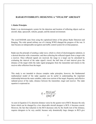
equation is expressed as:
As seen in Equation (3.3), detection distance varies by the quarter root of RCS. Because the only
factor which can be changed by a low observable aircraft designer is RCS, it becomes crucial.
However, the fact that reduction in the RCS decreases only by the fourth root of the distance,
requires designers to be very careful, because only dramatically large changes in RCS give
3
favorable results. If a given radar has a detection range of 100 miles against a target with a RCS
of 10 m2 , its approximate detection range to different RCS values calculated with basic radar
equation are shown in Table 2. This results again show that, only enormous reductions in the
RCS can make significant changes in the detection range, such as 1000 times reduction (RCS
from 1000 m2 to 1 m2 which equals to -30 dB) in RCS brings % 82.22 detection range reduction
(56.23 miles equals to % 17.78 of 316.23 miles, thus total detection range reduction is % 82.22).
Another example from Table 2 is; reducing the RCS from 81 to 5 m2 only changes the 39
detection range by about half (168.70 miles is twice as much to 84.09 miles), despite the fact that
this kind of reduction requires many design changes.
1. Radar Cross Section (RCS) and RCS Reduction Methods
A target is detected by the radar only when the radar’s receiver gets adequate energy back
from the target, furthermore, this energy must be above the electronic noise or signal to
noise threshold to be detected. There are many variables in the transmission scattering-
reflection sequence which determine the maximum detection range. These are transmitter
effective outgoing energy, beam width, RCS of the target, total energy back from the
target, antenna aperture (or size) and the receiver’s processing capability [14]. Among
these variables, RCS is the main concern of this study.
A radar beam is shaped in 3 dimensions like a cone, so as the range increases, the area
seen by this cone increases. However, with this increased range, the reflected target
energy and detected receiver energy diminishes. So, even in the best of circumstances,
only a small portion of the original energy can be used by the radar to process. RCS (m2 )
Approximate Detection Range (miles) Detection Range Reduction Rate (Compared to
4
1000 m2 RCS) 1000 316.23 ---- 100 177.83 % 43.77 81 168.70 % 46.65 10 100.00 %
68.38 5 84.09 % 73.41 1 56.23 % 82.22 40 Increasing the radar transmitter power, “a
long time Soviet Russian favorite [14]” or deploying bigger antennas with more gain
helps to obtain a longer detection range.. Furthermore, larger antennas and larger energy
generating units are cumbersome, especially for mobile systems. Nevertheless, with a
good understanding of basic electromagnetic principles and radar phenomena,
sophisticated radar designs that have better detection performance and greater precision
are being developed each passing day.
Up to this point, only the radar designer’s concerns are mentioned. For the stealth
designer, the only variable to decrease the detection range is RCS. This is why RCS is the
key term for low observables where reduction in reflected RF signal signature is intended.
Any attempt to make an asset RF low observable focuses on RCS. If a target’s RCS can
be decreased to a level low enough for its echo return to be below the detection threshold
of the radar, then the target is not detected. In this context, RCS reduction is a
countermeasure which has developed against radars and, conversely, new radar
techniques with more sophisticated designs are produced to detect targets with low RCS.
Radar cross section is the size of a target as seen by the radar [15]. In more scientific
words, RCS is a measure of the power that is returned or scattered in a given direction,
normalized with respect to power density of the incident field [15]. The normalization is
made to remove the effect of the range, and so the signature is not dependent on the
distance between the target and the receiver. The RCS helps to measure objects against a
common reference point, which is very useful in the low observable technology world in
determining the performance of design goals. In this context, RCS can also be described
as the size of a reflective sphere that would return the same amount of energy back. The
projected area of the sphere, or the area of a disk of the same diameter, is the RCS
number itself [14]. However, one important thing that should be understood is that this
area is not the geometrical cross section of the body. A proportional definition of RCS
can be made as:
5
RCS is a function of many factors. These factors include target geometry, its material
properties, the radar frequency and waveform, polarization of the incident wave and the
target aspect relative to the radar.
Considering the first two factors, which are under control of the stealth designer, there are
four main principles to reduce the RCS of an airplane. The principles are designing the
shape, using special materials (RAM) on the surfaces, active cancellation and passive
cancellation. In addition, a fifth consideration is plasma technology, which is also
sometimes included as an active cancellation type. However, there is no proven
application of this technology, other than some speculative Russian designs.
All of these methods have trade-offs. For example, shaping methods to decrease the RCS
of an aircraft may spoil its aerodynamic performance, and result in handling and
maneuverability problems. Material selections and coating also increase the weight, cost
and the maintenance requirements. Moreover, applications of these materials are usually
effective only in narrowband and in limited spatial regions. So the enemy’s likely threats
and the main mission of the aircraft must be considered very carefully in order to achieve
desired results. However, a combination of these RCS reduction methods is applied to
maintain the RCS below a specified threshold level over a range of frequencies and
angles.
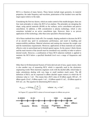
Other than its SI (International System of Units) derived unit of area, square meters, there
is also another way of measuring RCS, which is especially used in the electronics
engineering world. Most electronic engineers work with the decibel (dB), which helps to
make calculations dealing with very large or small numbers much easier. The dB
definition of RCS, can be expressed in dBsm (decibel square meters) in which the 42
reference value is 1 m2 . This means that a RCS value of 20 dBsm equals 100 m2 , 10
dBsm equals 10 m2 , 0 dBsm equals 1 m2 , -10 dBsm equals 0.1 m2 , -20 dBsm equals to
0.01 m2 , etc. The equation for determining RCS value is:
6
Exact RCS levels of military assets are classified, however, it is hypothesized that today's
true stealth aircraft have an RCS value around -30 dBsm (or 0.001 m2 ) and new
technological improvements promise to achieve values of -40 to -50 dBsm or 0.0001 to
0.00001 m2 . If these reductions are obtained, a radar, which could detect a nominal non
stealthy target with 5 m2 (~7 dBsm) RCS at 80 miles, could detect the target in the -50
dBsm case at a range of three miles, which, from an operational point of view, is too late
[14].
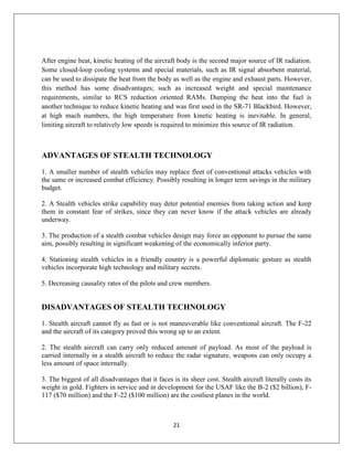
Figure 28 shows several aircraft and their approximate RCS values. Being classified,
these are not exact RCS of the aircraft. However, this figure can give an idea that
physical area is not the main concern and specially designed aircraft have remarkable
RCS reduction. The methods of RCS reduction will be discussed further in the following
sections.
FIGURE 1.2 RCS OF A AIRCRAFT
7
a. Shaping the Airframe
Before studying the shaping factor, the first RCS reduction principle, analyzing the major RCS
contributors of an aircraft, can be useful in gaining a better understanding of the subject. The
complex shape of an ordinary aircraft reveals many surfaces that can reflect incoming signals
back to the radar, including air inlets, compressor blades, vertical stabilizers, external payloads,
all cockpit instruments, all 44 cavities (discontinuities) and corners. Figure 29 shows these
contributors. All these contributors must be worked on very precisely to get desired reductions in
RCS values.
FIGURE 1.3 RCS OF A AIRCRAFT
Other than these contributors, the angle of the incoming radar signals is also very
important. This is because, as the normal of a surface to a signal changes, total reflected
energy and the RCS also change. For example, an aircraft with a 25 m2 head on RCS,
may have a 400 m2 broadside RCS. Figure 30 illustrates a RCS pattern of a target
reflecting a radar echo that is of relatively low frequency. The amplitude values for the
pattern are relative basis, so don’t represent a real aircraft. The target is located in a plane
where 0 degrees represents the nose on position. To understand RCS value variation of an
aircraft, in level flight, against radars at the same altitude but at different angles, the
target is rotated in the yaw axis. Such patterns are used to analyze the ability of an aircraft
to penetrate air defenses [15].
8
FIGURE 1.4 RCS PATTERN OF A AIRCRAFT
Some features of an airframe design present dramatically large RCS values. A flat panel,
which is a good reflector, is one of these, since it is normal to the radar beam. If this
surface is rotated, this will result in reflecting the incoming beams to other angles and
will create a smaller RCS for a monostatic receiver. Bill Sweetman, a former editor for
Jane’s, and a well-known Stealth advocate, quotes a stealth designer:
A flat panel is the brightest target, and also the dimmest. If the panel is at right angles to
an incoming beam, it is a perfect reflecting target. Rotate it along one axis and most of
the energy is deflected away from the radar. Rotate it along two axes and the RCS
becomes infinitesimal [15].
Conventional vertical stabilizers are one of these flat reflector panels. Canting them
inwards or outwards, with high-angles, can prevent incoming radiation from returning
back to the radar and also when a rudder-elevator combination is used, the retro reflector
of a dihedral, should be avoided. Here, a retro reflector dihedral is two surfaces that are
positioned at 90° from one another and these surfaces reflect the radar wave front back
along a vector that is parallel to but opposite in direction to the angle of incidence. Thus,
this double bounce maneuver will result in increasing the RCS.
9
Compressor blades are another large signal reflector. Along with increasing the RCS of a
target, some identification systems, such as radars using non cooperative target
recognition (NCTR) techniques, or one of the measurement and signature intelligence
systems (MASINT) technologies, can be used to collect and process the strong radar
returns from the engine compressor movements or periodic rotation of the blades of a
turbine to discriminate between enemy and friendly assets [15]. Thus, an aircraft engine
(with all possible components) should be kept out of reach of radar signals for low
observable designs.
Using wire mesh (as in the F-117 and RPV Q-2C), specially curved air inlet nacelles that
prevent the direct reach of RF signals to compressor blades (such as the B-1 B) and
carefully chosen engine (inlet) locations will also help to reduce RCS. However, placing
engines at their most optimum location to reduce RCS raises another important problem,
determining the direction of expected RF signals. For example, if a radar threat is
expected from below, putting the engine inlets at the top of the wing or airframe would
be an effective measure. This is the more likely situation for high altitude bombers,
reconnaissance and maritime patrol aircrafts. B-2 and F-117 bomber aircraft are good
examples of this kind of design. However, for an air-superiority fighter, estimating the
threat direction is a much more complex issue and there is no satisfying solution to this
problem. So, the use of serpentine ducts and inlet wire meshes are more effective
solutions to conceal the engines from radar signals.
Cockpits and their interior instruments, such as pilot’s helmet, seat, control components
and displays, reflect RF signals and increase the RCS, as the canopies and windshields
are normally transparent to the radar beams. Some special absorbent (or reflecting) layers
and coatings are used on the canopies of the stealth aircrafts to decrease the RCS of the
cockpit as well as their unique external shapes. Along with the stealth aircrafts, some
other fighters and EW assets such as F-16 Fighting Falcon and EA-6B Prowler also use
such coatings either to reduce RCS or to shield the powerful signal emitted by the
jammers from reaching the cockpit and crew. Controlled cockpit canopy shape, with
“transparent conductor thin film (vapor-deposited gold or indium tin oxide) [14].” on it,
block the incoming radar signals to reach the inner components and diminishes the
amount of reflected radar waves back to the radar. [7], [14].
Other RCS reduction methods concerned with shaping include avoiding gaps and holes in
the design and using covert gun ports, as shown in Figure 32, to hinder discontinuities on
the airframe surface. Performing high precision maintenance also helps to obtain and
sustain these low RCS levels. In one case, a single screw not tightened as required was
discovered to be the reason for an unexpected RCS increase in the F-117 prototype [14].
10
FIGURE 1.5 F-22 RAPTOR
The biggest effort in reducing the RCS is given to the forward aspects of the aircraft as
illustrated in Figure 33. However, in this case, greater returns for the other aspects or at
least some angles are inevitable. This tradeoff promises some advantage to
countermeasures of stealth such as well-designed bi-static radar networks. Secondly,
though shaping is the first principle in reducing RCS and must be carefully considered in
the design of low observables, long wavelengths are less affected by the shape of the
airframe and its details.
The RCS of the airframe can be reduced by geometrically controlling the incoming
signals’ reflection (directionally) and scattering. The first way to accomplish this is to use
flat surfaces and rectilinear surfaces all around the aircraft fuselage, which are oblique to
the radar signals. The F-117 Nighthawk, shown in Figure 34, is a very good example of
this kind of RCS reduction technique with shaping. F-117 Nighthawk uses careful
faceting technique to reduce RCS by scattering the signals in nearly every direction [14].
FIGURE 1.6 RF RCS
11
FIGURE 1.7 SCATTERING OF RF SIGNAL
The second reduction method is similar and involves reflecting the incoming signals in a
limited number of directions rather than scattering them in all directions. So a monostatic
receiver never gets the transmitted signal back, unless the radar signal reflects with two
90 degree angles from a surface, which is improbable when extreme look-down angles
are not present. If a bi static system is considered, its receiver can only get the radiated
beam when the spatial geometry is perfect [49]. In this technique, every straight line on
the entire airframe should be designed carefully; shape of the aircraft, from main aircraft
components such as wings, vertical and horizontal stabilizers, engine inlets, rudders, to
all other moving parts such as rudders, elevators, ailerons, weapon bays, landing gear
doors, canopy fasteners, etc., should be aligned in the direction of the few selected spikes
(to reflect the incoming signal towards only these specific directions), as shown in Figure
35. Using serrated (saw tooth shape shown in Figure 36) parts on surfaces may also help
achieve the desired results [14].
12
FIGURE 1.8 RCS REDUCTION
FIGURE 1.9 SHAPE FOR RCS REDUCTION
The third method is modeling the aircraft with a compact, smoothly blended external geometry
[14] which has changing curves. These curves do not have regular reflection characteristics and
they usually diminish the radar signal’s energy by capturing them inside the curvature. The B-2
Spirit, especially its engine nacelles, was 51 made with this kind of RCS technology. However,
this method requires very precise calculations, thus only the latest (after 1980s) low observable
aircraft have had the chance to use it in their computer based designs.
As mentioned, the main purpose of shaping is reducing or, ideally, eliminating the major RCS
contributors. However, shaping measures for low RCS has some tradeoffs, such as poor
aerodynamic performance, increased costs more maintenance requirements or less ordnance
capacity. Despite these drawbacks, which will be discussed in the following sections, the gains in
RCS reduction compensate for the diminished qualities for the purpose of improving aircraft
survivability during operations.
13
b. Non-Metallic Airframe, Radar Absorbent Material (RAM) and Radar
Absorbent Structure (RAS)
Stealth aircrafts should have extremely low RCS levels, however achieving such a goal is not
possible by shaping alone. Some material designs, such as radar absorbent material (RAM) and
radar absorbent structure (RAS) applications are also necessary.
Modern aircraft are generally made of composites, which consist of two or more different
materials that have dissimilar physical, chemical or electromagnetic properties. Generally,
composites are not metal and their RF signal reflection properties are very poor, thus non-
metallic airframes are considered to not show up on radar. However, the non-reflected RF signals
penetrate the non-metallic airframe and this time the reflection occurs from inside which results
from the radar images of engines, fuel pumps, electrical wiring and all other components.
Coating or painting the surfaces of airframes with special metallic finishing is the preferred way
to prevent the penetration of RF signals through composites. On the other hand, composites are
still important. Forms of composites, which consist of some poor conductors of electricity, such
as carbon products, and insulators, such as epoxy resin, are used in the airframes to cancel the
forms of creeping and travelling waves, by resisting electrical and magnetic currents which
reradiate [14].
Though RAM’s performance to decrease the RCS has been enhanced by a factor of ten, since the
mid-1980s, an expert still indicates “…shape, shape, shape and materials… [14]” as the most
important factors to design a stealth aircraft. It is clear that RAM is not an alternative for the
airframe design, and it cannot transform a conventional aircraft into a stealthy one, however for
better RCS values, some parts of the asset, especially edge reflections and cavities (such as
inlets), should be healed using RAM, where no other solution is likely [15].
One of the special RAM coatings is made of reinforced carbon carbon (RCC) [7]. For the most
part, RAMs, such as RCC, reduce RCS by absorbing (an amount of) the incoming signal and
converting RF energy into heat or by destructive interference. With their appropriate dielectric or
magnetic properties, different RAMs are used to get desired RCS results over the maximum
possible frequency range. RAM technology is based on the idea of establishing desirable
impedance which poses good matching and absorbing qualities, so that the RAM can accept and
then attenuate the incident wave [60]. Dielectric qualities of RAM can also be explained as
naturally occurring, electromagnetic waves of radar bouncing from conductive objects. However,
the molecular structure of the lossy materials causes RF energy to expend its energy by
producing heat. Then the heat is transferred to the aircraft and dissipated while the residual RF
energy loses its effectiveness, basically with help of friction and inertia or molecular oscillations.
Finally, this results in less reflection back to the radar receiver [14].
Together with absorption, another way of RCS reduction, by using RAM, is destructive
interference. However, there is an important distinction between the phenomenon of absorption
14
(Figure 37) and destructive interference applications. As mentioned above, the absorption
process, which covers ohmic loss (based on the motion of free charges in an imperfect
conductor), dielectric loss (based on permittivity), and magnetic loss (based on permeability), is
possible by transferring the incident RF wave’s energy to the airframe material as it passes
through. On the other hand, the destructive interference (also known as “resonant RAM” or
“impedance loading”) principal is based on coatings, or the “Salisbury Screen” method, which
are used to reduce RCS by 53 cancellations of multiple reflections [15]. This method is
considered both a RAM and a passive cancellation method. This study will discuss destructive
interference in the passive cancellation technique section.
FIGURE 2.0 RADAR ABSORBING MATERIALS
RAM includes many types of materials. Six RAM examples, low dielectric foam (epoxy);
lightweight lossy foam (urethane); thermoplastic foam (polytherimide); sprayable lightweight
foam (urethane); thin MAGRAM silicone resin sheet; and resistive card (R-card) made of
metalized Kapton, can be seen in Figure 38 in the order of clockwise from upper left [61].
Another example, a ferrite-based paint, which is called “iron ball”, was used on the U-2 and SR-
71 to reduce the RCS.
15
FIGURE 2.1 RADAR ABSORBING SHEETS
RAM has some limitations. Although the use of RAM is strengthening for low observability, it
never gives perfect results and can never be assumed to decrease an aircraft’s RCS values to a
large extent. It can absorb a portion of the incident energy, with the rest being reflected.
Moreover, certain kinds of RAM can give expected results only for certain frequencies and
angles of the incident radar wave. Using different kinds of RAM to broaden the RF spectral
coverage, along with thicker and heavier amounts, increases the effectiveness. However, the
optimum RAM weight and depth should be evaluated while considering the impact of the
application of bulky coatings, which may demolish other flight and mission characteristics of the
asset. Inconvenient weather conditions, such as rain, may also decrease the performance of most
RAM. Furthermore, aircraft shelters should be constructed with special qualities to provide
required RAM protection and maintenance. This is the reason that early B-2 planes were not
deployed at US bases abroad where these kind of special shelters were not available [14].
Because thick and solid RAM coatings or paintings, which are heavy and bulky, are required but
not feasible to get desired RCS reduction over wider bandwidths, an alternative method of using
such materials at the inner skin of the airframe is 55 preferred. Radar absorbing structures
involve building special materials in special ways, such as honeycomb, as shown in Figure 39, to
attenuate radar waves into load-bearing structure [14].
16
FIGURE 2.2 RADAR ABSORBING HONEYCOMB STRUCTURE
The honeycomb structures have very important advantages. First of all, their hexagonal passages,
which are bonded together, are physically very strong, flexible and light. From a RCS
perspective, their depth, which does not cause considerable weight, is used to form many
surfaces to reflect, absorb and attenuate the radar signal. One kind of honeycomb is made up of
an outer skin of kevlar/epoxy composite, which is transparent to radar, and an inner skin of
reflective graphite/ epoxy [49]. The nomex core, between them, has absorbent properties and its
increasing density, front to rear of the honeycomb, improves the effectiveness. The small amount
of front-face reflection of the incident radar wave is followed by the radar wave to reach the
thinly spread absorber on the outer edges of the core where another small part of the energy is
absorbed and the remainder is bounced. So, the travelling wave meets more densely loaded core
material as it goes on. Each time, some amount of energy is either absorbed or reflected, and
finally the outermost layer of the absorber once again attenuates it [14] and the radar wave,
which is checked into the structure, never checks out to free space again [14].
17
Another RAS form is used on the leading and trailing edges of low observables, such as the
wings and fuselage skin strakes of the SR-71 Blackbird, which is depicted in Figure 40. In this
method, gradually increasing absorption is applied to trap the energy, similar to the honeycomb
structure. However, in this case, the physical shape of the structure is a saw-tooth pattern. The
external surface is coated with a high frequency ferrite absorber. The interior begins with a low-
absorption layer and is followed by a more absorbent layer, so; while the deepness increase the
absorbent properties are also augmented. The “V” shaped geometry, shown in Figure 41, causes
the radar signal to bounce towards the opposite side, while the material properties of the structure
absorb and provide the incoming signal to diminish the energy, so each bounce results in the loss
of some amount of the energy [14].
FIGURE 2.3 TRAPPING INCOMING SIGNAL
18
C. Passive Cancellation System
Special material used for signal cancellation purposes to reduce RCS fall into two categories:
RAM RCS reduction methods (resonant RAM) and passive cancellation. The resonant RAM
method was also introduced as destructive interference or impedance loading in RAM
applications. Here all these terms and so passive cancellation system refers to “RCS reduction by
introducing a secondary scatter to cancel with the reflection of the primary target [60].”
In this method, special coatings, which are also called “resonant absorbers”, are chosen to cancel
the incoming signals by being reflected two times (some times more than two is also possible for
wider frequency covering), one from the front and the other from the back of the layer.
Theoretically, having a back face wave that totally travels one half wavelength more than the one
that is reflected from the first layer is essential. Having the correct thickness causes the second
reflection to have a 180 degree phase difference with the round-trip (first layer) reflection, thus
first and second waves will cancel each other. However, this method strictly relies on layer
thickness or ¼th of the wavelength matching.
This method, is also known as “Salisbury screen”, and illustrated in Figure 43. A resistive
screen, which is placed in front of the reflective back plate, bounces nearly 50 % of the incident
radar beam (blue wave in the Figure 43) back to incoming direction (purple wave in Figure 43),
while the other 50% of the radar wave passes through and reflect from that grey plate (red wave
in Figure 43). When the distance between these two plates are ¼th of radar signal’s wavelength,
red and purple waves cancels each other. Because such a thickness is only effective for specific
frequencies, this cancellation is called as a “narrowband technique.” On the other hand, from a
RAM application techniques perspective, dielectric and magnetic loss mechanisms are
categorized as broadband absorbers, while they can generally be deployed to cover wider
frequency bands than passive cancellation coatings [15].
FIGURE 2.4 SALISBURY SCREEN
19
d. Plasma Stealth
Plasma is a partially ionized and electrically conductive gas by means of the ability of the
positive and negative charges to move somewhat independently [63]. Its free electrons make
plasma respond strongly to electromagnetic fields. Thus using plasma, which is sometimes
considered an active cancellation technique, has been studied and proposed as a possible method
of RCS reduction. The inspiration for this method emerged in the late 1950s after spacecraft with
a natural plasma layer over their airframes experienced communication interruption incidents
while traveling through the ionosphere. Basically, radar waves (actually all electromagnetic
waves of certain frequencies) traveling through this conductive plasma cause electrons to
exchange their places, ending up with the electromagnetic waves losing their energy and
transforming it to other forms, such as heat. Interaction between plasma and electromagnetic
radiation is strongly dependent on the physical properties and parameters of the plasma [6]. The
most dominating of these properties are the temperature and the density of the plasma. Another
important issue is frequency of the incident radar beam. Radar waves, below a specific frequency,
are reflected by plasma layer. Plasma layer’s physical properties have significant effect on this
process. Long distance communications with HF signals by means of ionosphere scattering and
reflection is a good example of this same phenomena. Thus, RCS reduction plasma devices
should also control and dynamically adjust the plasma properties, such as density, temperature
and composition, for effective radar absorption results.
Plasma stealth technology has some drawbacks from a low observables perspective. Some of
these include, emitting own electromagnetic radiation with a visible glow, existence of a plasma
trail of ionized air behind the aircraft [64] before dissipation by the atmosphere, and difficulty in
producing a radar-absorbent plasma around an entire aircraft traveling at high speed [64].
However, some Russian scientists have declared achieving a hundredfold RCS reduction with
plasma technology and this result (if real) is sufficient enough to focus on this method for further
research and success in the stealth world [64]. 63 Another application of plasma is utilizing this
technology to deploy antenna surfaces to generate low observability characteristics. While metal
antenna poles are reflective parts, a hollow glass tube filled with low pressure plasma can
provide an entirely radar transparent surface when not in use [15].
D. IR SIGNATURE AND IR STEALTH
All substances with a temperature above absolute zero (0° K, or -273.15° C, or - 459.67° F),
emit electromagnetic waves. The heat content of a material produces 67 molecular vibrations
which cause electron oscillations. These oscillations provide electromagnetic coupling that
produces an emission of energy. This emission is called infrared radiation (IR). IR has a
wavelength spectrum of 0.7 to 14 micrometers, and the amount of radiation emitted is primarily
dependent on the physical temperature of the associated object (proportionally). The emissivity
20
characteristics of an object are related to the material’s molecular structure and the surface
conditions of the object. IR energy that comes from another body is either absorbed or reradiated
by the object according to its emissivity properties [3].
As with visible light, IR energy also travels in a straight line at speed of light. Similarly, IR
energy is either reflected or absorbed and converted to heat when it hits the surface of an object.
These absorption and reflection qualities change with material specifications. For example,
polished surfaces reflect more IR energy but also have a much lower emissivity than matte
surfaces [8].
IR energy considerations are important to stealth designers, because IR detectors, also known as
infrared homing devices, such as passive missile guidance systems, can use IR emissions from a
target to track it. Detector systems, especially missile guiding seekers, which detect the radiated
infrared signals of their target, are often referred to as "heat-seekers". If unaided by IR
countermeasures, aircraft are vulnerable to detection by such systems by means of the strongly
radiated energy from their hot bodies. Some precautions to mitigate such detection include,
reducing or suppressing an aircraft’s IR signature and adding some noise, deploying decoys or
flares, and jamming the sensor by emitting high power signals towards the detector.
Another method to decrease IR signature is the shaping of exhaust geometry. Exhausts that are
shaped flat and wide, as shown in Figure 51, are effective in this regard. This increases the
perimeter of the plum compared to conventional round nozzles, and 70 results in an increased
mixing rate of exhaust gases, cooling them with air. This reduces probability of detection, but
thrust efficiency is decreased with flat and wide designs. High bypass engines also benefit from
the mixing of air with exhaust for exhaust nozzle temperature reduction purposes. Masking the
hot turbine stages with curved jet pipes and concealing the forward emissions of the engine with
curved air intakes are other measures to reduce IR signature.
FIGURE 2.5 F-22 RAPTOR
21
After engine heat, kinetic heating of the aircraft body is the second major source of IR radiation.
Some closed-loop cooling systems and special materials, such as IR signal absorbent material,
can be used to dissipate the heat from the body as well as the engine and exhaust parts. However,
this method has some disadvantages; such as increased weight and special maintenance
requirements, similar to RCS reduction oriented RAMs. Dumping the heat into the fuel is
another technique to reduce kinetic heating and was first used in the SR-71 Blackbird. However,
at high mach numbers, the high temperature from kinetic heating is inevitable. In general,
limiting aircraft to relatively low speeds is required to minimize this source of IR radiation.
ADVANTAGES OF STEALTH TECHNOLOGY
1. A smaller number of stealth vehicles may replace fleet of conventional attacks vehicles with
the same or increased combat efficiency. Possibly resulting in longer term savings in the military
budget.
2. A Stealth vehicles strike capability may deter potential enemies from taking action and keep
them in constant fear of strikes, since they can never know if the attack vehicles are already
underway.
3. The production of a stealth combat vehicles design may force an opponent to pursue the same
aim, possibly resulting in significant weakening of the economically inferior party.
4. Stationing stealth vehicles in a friendly country is a powerful diplomatic gesture as stealth
vehicles incorporate high technology and military secrets.
5. Decreasing causality rates of the pilots and crew members.
DISADVANTAGES OF STEALTH TECHNOLOGY
1. Stealth aircraft cannot fly as fast or is not maneuverable like conventional aircraft. The F-22
and the aircraft of its category proved this wrong up to an extent.
2. The stealth aircraft can carry only reduced amount of payload. As most of the payload is
carried internally in a stealth aircraft to reduce the radar signature, weapons can only occupy a
less amount of space internally.
3. The biggest of all disadvantages that it faces is its sheer cost. Stealth aircraft literally costs its
weight in gold. Fighters in service and in development for the USAF like the B-2 ($2 billion), F-
117 ($70 million) and the F-22 ($100 million) are the costliest planes in the world.
22
FUTURE SCOPE
Stealth technology is clearly the future of air combat. In the future, as air defense systems grow
more accurate and deadly, stealth technology can be a factor for a decisive by a country over the
other. In the future, stealth technology will not only be incorporated in fighters and bombers but
also in ships, helicopters, tanks and transport planes. These are evident from the RAH-66
"Comanche" and the Sea Shadow ship. Ever since the Wright brothers flew the first powered
flight, the advancements in this particular field of technology has seen staggering heights. Stealth
technology is just one of the advancements that we have seen. In due course of time we can see
many improvements in the field of military aviation which would one-day even make stealth
technology obsolete.
CONCLUSION
Stealth technology is clearly the future of air combat. In the future, as air defense systems grow
more accurate and deadly, stealth technology can be a factor for a decisive by a country over the
other. In the future, stealth technology will not only be incorporated in fighters and bombers but
also in ships, helicopters, tanks and transport planes. Ever since the Wright brothers flew the first
powered flight, the advancements in this particular field of technology have seen staggering
heights. Stealth technology is just one of the advancements that we have seen. In due course of
time we can see many improvements in the field of military aviation which would even make
stealth technology obsolete very soon within a decade.
23
REFERENCES
1. http://www.totalairdominance.50megs.com/articles/stealth.htm
2. http://en.wikipedia.org/wiki/Stealth_technology
3. http://en.wikipedia.org/wiki/Radar
4. http://en.wikipedia.org/wiki/Stealth_ship
5. http://www.resonancepub.com/images/stealth_ship.gif
6. http://images.google.co.in/images
7. http://science.howstuffworks.com/question69.htm
8. http://www.espionageinfo.com/Sp-Te/Stealth-Technology.html
9. http://www.airplanedesign.info/51.htm
10. http://www.hitechweb.genezis.eu/stealth4f_soubory/image013.jpg
11. http://www.geocities.com/electrogravitics/scm.html
12. http://www.razorworks.com/enemyengaged/chguide/images/lo- reflecting.gif
13. htp://www.x20.org/library/thermal/pdm/ir_thermography.htm
14. Dimitris V. Dranidis, “Airborne Stealth in a Nutshell-Part I,” the Magazine of the Computer
Harpoon Community http://www.harpoonhq.com/waypoint/, (Accessed February 2009).
15. William E. Bahret, “The Beginnings of Stealth Technology,” IEEE Transactions on
Aerospace and Electronic Systems Vol.29, No 4 October 1993.
16. Serdar Cadirci,” RF stealth (or low observable) and counter RF stealth technologies”.

More Related Content

What's hot

Stealth Technology by Ankit ppt
Stealth Technology by Ankit pptStealth Technology by Ankit ppt
Stealth Technology by Ankit ppt
Ankit Kumar
 
Report on RADAR stealth technology
Report on RADAR stealth technologyReport on RADAR stealth technology
Report on RADAR stealth technologyPragati Garg
 
Stealth technology(supreeth)
Stealth technology(supreeth)Stealth technology(supreeth)
Stealth technology(supreeth)supreethmysore
 
Radar Cross Section
Radar Cross SectionRadar Cross Section
Radar Cross Section
Nann Wai
 
Mechanical Aspects in Stealth Technology
Mechanical Aspects in Stealth TechnologyMechanical Aspects in Stealth Technology
Mechanical Aspects in Stealth Technology
BipinKumarJha1
 
Stealth technology
Stealth technologyStealth technology
Stealth technology
Rakesh Rao
 
Aircraft stealth technology discussed
Aircraft stealth technology discussedAircraft stealth technology discussed
Aircraft stealth technology discussed
Ashish Joshi
 
Stealth technology
Stealth technologyStealth technology
Stealth technology
ayush sharma
 
Radar Powerpoint
Radar PowerpointRadar Powerpoint
Radar Powerpoint
Ryan rice
 
Radar Absorption Materials
Radar Absorption MaterialsRadar Absorption Materials
Radar Absorption Materials
Kutluhan Utku TÜMEN
 
Stealth technology in aircrafts
Stealth technology in aircraftsStealth technology in aircrafts
Stealth technology in aircrafts
Surender Singh
 
Stealth Technology
Stealth Technology Stealth Technology
Stealth Technology
abdulsamad alhamawande
 
Radar
RadarRadar
RADAR AND STEALTH TECHNOLOGY
RADAR AND STEALTH TECHNOLOGYRADAR AND STEALTH TECHNOLOGY
RADAR AND STEALTH TECHNOLOGY
Paul singh
 
Stealth Technology in Naval Warfare Report
Stealth Technology in Naval Warfare ReportStealth Technology in Naval Warfare Report
Stealth Technology in Naval Warfare Report
Siddharth Bhatnagar
 
Stealth aircraft technology ppt
Stealth aircraft technology pptStealth aircraft technology ppt
Stealth aircraft technology ppt
Hanim MS
 
Stealth aircraft and anti stealth technology
Stealth aircraft and anti stealth technologyStealth aircraft and anti stealth technology
Stealth aircraft and anti stealth technology
naveen kumar
 

What's hot (20)

Stealth Technology by Ankit ppt
Stealth Technology by Ankit pptStealth Technology by Ankit ppt
Stealth Technology by Ankit ppt
 
Report on RADAR stealth technology
Report on RADAR stealth technologyReport on RADAR stealth technology
Report on RADAR stealth technology
 
Stealth technology(supreeth)
Stealth technology(supreeth)Stealth technology(supreeth)
Stealth technology(supreeth)
 
Radar Cross Section
Radar Cross SectionRadar Cross Section
Radar Cross Section
 
Mechanical Aspects in Stealth Technology
Mechanical Aspects in Stealth TechnologyMechanical Aspects in Stealth Technology
Mechanical Aspects in Stealth Technology
 
Stealth technology
Stealth technologyStealth technology
Stealth technology
 
Aircraft stealth technology discussed
Aircraft stealth technology discussedAircraft stealth technology discussed
Aircraft stealth technology discussed
 
Stealth technology
Stealth technologyStealth technology
Stealth technology
 
Radar
RadarRadar
Radar
 
Radar Powerpoint
Radar PowerpointRadar Powerpoint
Radar Powerpoint
 
Radar Absorption Materials
Radar Absorption MaterialsRadar Absorption Materials
Radar Absorption Materials
 
Stealth technology in aircrafts
Stealth technology in aircraftsStealth technology in aircrafts
Stealth technology in aircrafts
 
Stealth Technology
Stealth Technology Stealth Technology
Stealth Technology
 
Radar
RadarRadar
Radar
 
RADAR AND STEALTH TECHNOLOGY
RADAR AND STEALTH TECHNOLOGYRADAR AND STEALTH TECHNOLOGY
RADAR AND STEALTH TECHNOLOGY
 
Stealth Technology in Naval Warfare Report
Stealth Technology in Naval Warfare ReportStealth Technology in Naval Warfare Report
Stealth Technology in Naval Warfare Report
 
Stealth
StealthStealth
Stealth
 
stealth technology
stealth technologystealth technology
stealth technology
 
Stealth aircraft technology ppt
Stealth aircraft technology pptStealth aircraft technology ppt
Stealth aircraft technology ppt
 
Stealth aircraft and anti stealth technology
Stealth aircraft and anti stealth technologyStealth aircraft and anti stealth technology
Stealth aircraft and anti stealth technology
 

Similar to Report on Stealth technology

Stealth Radar
Stealth RadarStealth Radar
Stealth Radar
Pramod Devireddy
 
Radar crossection area reduction techniques
Radar crossection area reduction techniques Radar crossection area reduction techniques
Radar crossection area reduction techniques
MUKULWADHOKAR
 
D0312015019
D0312015019D0312015019
D0312015019
inventy
 
G041034850
G041034850G041034850
G041034850
IOSR-JEN
 
Radar Cross Section Reduction
Radar Cross Section ReductionRadar Cross Section Reduction
Radar Cross Section Reduction
yashwanth sankoju
 
A Review on Identification of RADAR Range for the Target by using C Band
A Review on Identification of RADAR Range for the Target by using C BandA Review on Identification of RADAR Range for the Target by using C Band
A Review on Identification of RADAR Range for the Target by using C Band
IRJET Journal
 
4.11 radar cross section (rcs)
4.11 radar cross section (rcs)4.11 radar cross section (rcs)
4.11 radar cross section (rcs)
Javier Gismero
 
Island Air Defence: Challenges, Novel Surveillance Concepts and Advanced Rada...
Island Air Defence: Challenges, Novel Surveillance Concepts and Advanced Rada...Island Air Defence: Challenges, Novel Surveillance Concepts and Advanced Rada...
Island Air Defence: Challenges, Novel Surveillance Concepts and Advanced Rada...
Ashwin Samales
 
Semester 1 seminar (roll no. 192606)
Semester 1  seminar (roll no. 192606)Semester 1  seminar (roll no. 192606)
Semester 1 seminar (roll no. 192606)
Kush Singla
 
Microwave remote sensing
Microwave remote sensingMicrowave remote sensing
Microwave remote sensing
Mohsin Siddique
 
CHAPTER 1 PRINCIPLES OF RADAR.pptx
CHAPTER 1 PRINCIPLES OF RADAR.pptxCHAPTER 1 PRINCIPLES OF RADAR.pptx
CHAPTER 1 PRINCIPLES OF RADAR.pptx
JaamacAbdikhayr
 
Laser ScanningLaser scanning is an emerging data acquisition techn.pdf
Laser ScanningLaser scanning is an emerging data acquisition techn.pdfLaser ScanningLaser scanning is an emerging data acquisition techn.pdf
Laser ScanningLaser scanning is an emerging data acquisition techn.pdf
anjaniar7gallery
 
Radar communication
Radar communicationRadar communication
Radar communication
Saurabh Kumar
 
C011121114
C011121114C011121114
C011121114
IOSR Journals
 
Chapter 1-generality
Chapter 1-generalityChapter 1-generality
Chapter 1-generality
Rima Assaf
 
Introduction to Radar System & Component Tests
Introduction to Radar System & Component TestsIntroduction to Radar System & Component Tests
Introduction to Radar System & Component Tests
Rohde & Schwarz North America
 
Stealth Technology
Stealth TechnologyStealth Technology
Stealth Technology
ROHITH
 

Similar to Report on Stealth technology (20)

Stealth Radar
Stealth RadarStealth Radar
Stealth Radar
 
Radar crossection area reduction techniques
Radar crossection area reduction techniques Radar crossection area reduction techniques
Radar crossection area reduction techniques
 
D0312015019
D0312015019D0312015019
D0312015019
 
G041034850
G041034850G041034850
G041034850
 
Radar Cross Section Reduction
Radar Cross Section ReductionRadar Cross Section Reduction
Radar Cross Section Reduction
 
A Review on Identification of RADAR Range for the Target by using C Band
A Review on Identification of RADAR Range for the Target by using C BandA Review on Identification of RADAR Range for the Target by using C Band
A Review on Identification of RADAR Range for the Target by using C Band
 
4.11 radar cross section (rcs)
4.11 radar cross section (rcs)4.11 radar cross section (rcs)
4.11 radar cross section (rcs)
 
Island Air Defence: Challenges, Novel Surveillance Concepts and Advanced Rada...
Island Air Defence: Challenges, Novel Surveillance Concepts and Advanced Rada...Island Air Defence: Challenges, Novel Surveillance Concepts and Advanced Rada...
Island Air Defence: Challenges, Novel Surveillance Concepts and Advanced Rada...
 
Dr. Wiley - PRI Analysis and Deinterleaving
Dr. Wiley - PRI Analysis and DeinterleavingDr. Wiley - PRI Analysis and Deinterleaving
Dr. Wiley - PRI Analysis and Deinterleaving
 
Basics on Radar Cross Section
Basics on Radar Cross SectionBasics on Radar Cross Section
Basics on Radar Cross Section
 
Semester 1 seminar (roll no. 192606)
Semester 1  seminar (roll no. 192606)Semester 1  seminar (roll no. 192606)
Semester 1 seminar (roll no. 192606)
 
Microwave remote sensing
Microwave remote sensingMicrowave remote sensing
Microwave remote sensing
 
CHAPTER 1 PRINCIPLES OF RADAR.pptx
CHAPTER 1 PRINCIPLES OF RADAR.pptxCHAPTER 1 PRINCIPLES OF RADAR.pptx
CHAPTER 1 PRINCIPLES OF RADAR.pptx
 
Laser ScanningLaser scanning is an emerging data acquisition techn.pdf
Laser ScanningLaser scanning is an emerging data acquisition techn.pdfLaser ScanningLaser scanning is an emerging data acquisition techn.pdf
Laser ScanningLaser scanning is an emerging data acquisition techn.pdf
 
Radar communication
Radar communicationRadar communication
Radar communication
 
C011121114
C011121114C011121114
C011121114
 
Chapter 1-generality
Chapter 1-generalityChapter 1-generality
Chapter 1-generality
 
Introduction to Radar System & Component Tests
Introduction to Radar System & Component TestsIntroduction to Radar System & Component Tests
Introduction to Radar System & Component Tests
 
Stealth Technology
Stealth TechnologyStealth Technology
Stealth Technology
 
LiDAR work
LiDAR workLiDAR work
LiDAR work
 

Recently uploaded

The Benefits and Techniques of Trenchless Pipe Repair.pdf
The Benefits and Techniques of Trenchless Pipe Repair.pdfThe Benefits and Techniques of Trenchless Pipe Repair.pdf
The Benefits and Techniques of Trenchless Pipe Repair.pdf
Pipe Restoration Solutions
 
Top 10 Oil and Gas Projects in Saudi Arabia 2024.pdf
Top 10 Oil and Gas Projects in Saudi Arabia 2024.pdfTop 10 Oil and Gas Projects in Saudi Arabia 2024.pdf
Top 10 Oil and Gas Projects in Saudi Arabia 2024.pdf
Teleport Manpower Consultant
 
Architectural Portfolio Sean Lockwood
Architectural Portfolio Sean LockwoodArchitectural Portfolio Sean Lockwood
Architectural Portfolio Sean Lockwood
seandesed
 
Immunizing Image Classifiers Against Localized Adversary Attacks
Immunizing Image Classifiers Against Localized Adversary AttacksImmunizing Image Classifiers Against Localized Adversary Attacks
Immunizing Image Classifiers Against Localized Adversary Attacks
gerogepatton
 
The role of big data in decision making.
The role of big data in decision making.The role of big data in decision making.
The role of big data in decision making.
ankuprajapati0525
 
ethical hacking-mobile hacking methods.ppt
ethical hacking-mobile hacking methods.pptethical hacking-mobile hacking methods.ppt
ethical hacking-mobile hacking methods.ppt
Jayaprasanna4
 
Governing Equations for Fundamental Aerodynamics_Anderson2010.pdf
Governing Equations for Fundamental Aerodynamics_Anderson2010.pdfGoverning Equations for Fundamental Aerodynamics_Anderson2010.pdf
Governing Equations for Fundamental Aerodynamics_Anderson2010.pdf
WENKENLI1
 
Investor-Presentation-Q1FY2024 investor presentation document.pptx
Investor-Presentation-Q1FY2024 investor presentation document.pptxInvestor-Presentation-Q1FY2024 investor presentation document.pptx
Investor-Presentation-Q1FY2024 investor presentation document.pptx
AmarGB2
 
Sachpazis:Terzaghi Bearing Capacity Estimation in simple terms with Calculati...
Sachpazis:Terzaghi Bearing Capacity Estimation in simple terms with Calculati...Sachpazis:Terzaghi Bearing Capacity Estimation in simple terms with Calculati...
Sachpazis:Terzaghi Bearing Capacity Estimation in simple terms with Calculati...
Dr.Costas Sachpazis
 
Standard Reomte Control Interface - Neometrix
Standard Reomte Control Interface - NeometrixStandard Reomte Control Interface - Neometrix
Standard Reomte Control Interface - Neometrix
Neometrix_Engineering_Pvt_Ltd
 
Planning Of Procurement o different goods and services
Planning Of Procurement o different goods and servicesPlanning Of Procurement o different goods and services
Planning Of Procurement o different goods and services
JoytuBarua2
 
一比一原版(SFU毕业证)西蒙菲莎大学毕业证成绩单如何办理
一比一原版(SFU毕业证)西蒙菲莎大学毕业证成绩单如何办理一比一原版(SFU毕业证)西蒙菲莎大学毕业证成绩单如何办理
一比一原版(SFU毕业证)西蒙菲莎大学毕业证成绩单如何办理
bakpo1
 
road safety engineering r s e unit 3.pdf
road safety engineering  r s e unit 3.pdfroad safety engineering  r s e unit 3.pdf
road safety engineering r s e unit 3.pdf
VENKATESHvenky89705
 
ML for identifying fraud using open blockchain data.pptx
ML for identifying fraud using open blockchain data.pptxML for identifying fraud using open blockchain data.pptx
ML for identifying fraud using open blockchain data.pptx
Vijay Dialani, PhD
 
Student information management system project report ii.pdf
Student information management system project report ii.pdfStudent information management system project report ii.pdf
Student information management system project report ii.pdf
Kamal Acharya
 
在线办理(ANU毕业证书)澳洲国立大学毕业证录取通知书一模一样
在线办理(ANU毕业证书)澳洲国立大学毕业证录取通知书一模一样在线办理(ANU毕业证书)澳洲国立大学毕业证录取通知书一模一样
在线办理(ANU毕业证书)澳洲国立大学毕业证录取通知书一模一样
obonagu
 
Hybrid optimization of pumped hydro system and solar- Engr. Abdul-Azeez.pdf
Hybrid optimization of pumped hydro system and solar- Engr. Abdul-Azeez.pdfHybrid optimization of pumped hydro system and solar- Engr. Abdul-Azeez.pdf
Hybrid optimization of pumped hydro system and solar- Engr. Abdul-Azeez.pdf
fxintegritypublishin
 
CME397 Surface Engineering- Professional Elective
CME397 Surface Engineering- Professional ElectiveCME397 Surface Engineering- Professional Elective
CME397 Surface Engineering- Professional Elective
karthi keyan
 
DESIGN A COTTON SEED SEPARATION MACHINE.docx
DESIGN A COTTON SEED SEPARATION MACHINE.docxDESIGN A COTTON SEED SEPARATION MACHINE.docx
DESIGN A COTTON SEED SEPARATION MACHINE.docx
FluxPrime1
 
Hierarchical Digital Twin of a Naval Power System
Hierarchical Digital Twin of a Naval Power SystemHierarchical Digital Twin of a Naval Power System
Hierarchical Digital Twin of a Naval Power System
Kerry Sado
 

Recently uploaded (20)

The Benefits and Techniques of Trenchless Pipe Repair.pdf
The Benefits and Techniques of Trenchless Pipe Repair.pdfThe Benefits and Techniques of Trenchless Pipe Repair.pdf
The Benefits and Techniques of Trenchless Pipe Repair.pdf
 
Top 10 Oil and Gas Projects in Saudi Arabia 2024.pdf
Top 10 Oil and Gas Projects in Saudi Arabia 2024.pdfTop 10 Oil and Gas Projects in Saudi Arabia 2024.pdf
Top 10 Oil and Gas Projects in Saudi Arabia 2024.pdf
 
Architectural Portfolio Sean Lockwood
Architectural Portfolio Sean LockwoodArchitectural Portfolio Sean Lockwood
Architectural Portfolio Sean Lockwood
 
Immunizing Image Classifiers Against Localized Adversary Attacks
Immunizing Image Classifiers Against Localized Adversary AttacksImmunizing Image Classifiers Against Localized Adversary Attacks
Immunizing Image Classifiers Against Localized Adversary Attacks
 
The role of big data in decision making.
The role of big data in decision making.The role of big data in decision making.
The role of big data in decision making.
 
ethical hacking-mobile hacking methods.ppt
ethical hacking-mobile hacking methods.pptethical hacking-mobile hacking methods.ppt
ethical hacking-mobile hacking methods.ppt
 
Governing Equations for Fundamental Aerodynamics_Anderson2010.pdf
Governing Equations for Fundamental Aerodynamics_Anderson2010.pdfGoverning Equations for Fundamental Aerodynamics_Anderson2010.pdf
Governing Equations for Fundamental Aerodynamics_Anderson2010.pdf
 
Investor-Presentation-Q1FY2024 investor presentation document.pptx
Investor-Presentation-Q1FY2024 investor presentation document.pptxInvestor-Presentation-Q1FY2024 investor presentation document.pptx
Investor-Presentation-Q1FY2024 investor presentation document.pptx
 
Sachpazis:Terzaghi Bearing Capacity Estimation in simple terms with Calculati...
Sachpazis:Terzaghi Bearing Capacity Estimation in simple terms with Calculati...Sachpazis:Terzaghi Bearing Capacity Estimation in simple terms with Calculati...
Sachpazis:Terzaghi Bearing Capacity Estimation in simple terms with Calculati...
 
Standard Reomte Control Interface - Neometrix
Standard Reomte Control Interface - NeometrixStandard Reomte Control Interface - Neometrix
Standard Reomte Control Interface - Neometrix
 
Planning Of Procurement o different goods and services
Planning Of Procurement o different goods and servicesPlanning Of Procurement o different goods and services
Planning Of Procurement o different goods and services
 
一比一原版(SFU毕业证)西蒙菲莎大学毕业证成绩单如何办理
一比一原版(SFU毕业证)西蒙菲莎大学毕业证成绩单如何办理一比一原版(SFU毕业证)西蒙菲莎大学毕业证成绩单如何办理
一比一原版(SFU毕业证)西蒙菲莎大学毕业证成绩单如何办理
 
road safety engineering r s e unit 3.pdf
road safety engineering  r s e unit 3.pdfroad safety engineering  r s e unit 3.pdf
road safety engineering r s e unit 3.pdf
 
ML for identifying fraud using open blockchain data.pptx
ML for identifying fraud using open blockchain data.pptxML for identifying fraud using open blockchain data.pptx
ML for identifying fraud using open blockchain data.pptx
 
Student information management system project report ii.pdf
Student information management system project report ii.pdfStudent information management system project report ii.pdf
Student information management system project report ii.pdf
 
在线办理(ANU毕业证书)澳洲国立大学毕业证录取通知书一模一样
在线办理(ANU毕业证书)澳洲国立大学毕业证录取通知书一模一样在线办理(ANU毕业证书)澳洲国立大学毕业证录取通知书一模一样
在线办理(ANU毕业证书)澳洲国立大学毕业证录取通知书一模一样
 
Hybrid optimization of pumped hydro system and solar- Engr. Abdul-Azeez.pdf
Hybrid optimization of pumped hydro system and solar- Engr. Abdul-Azeez.pdfHybrid optimization of pumped hydro system and solar- Engr. Abdul-Azeez.pdf
Hybrid optimization of pumped hydro system and solar- Engr. Abdul-Azeez.pdf
 
CME397 Surface Engineering- Professional Elective
CME397 Surface Engineering- Professional ElectiveCME397 Surface Engineering- Professional Elective
CME397 Surface Engineering- Professional Elective
 
DESIGN A COTTON SEED SEPARATION MACHINE.docx
DESIGN A COTTON SEED SEPARATION MACHINE.docxDESIGN A COTTON SEED SEPARATION MACHINE.docx
DESIGN A COTTON SEED SEPARATION MACHINE.docx
 
Hierarchical Digital Twin of a Naval Power System
Hierarchical Digital Twin of a Naval Power SystemHierarchical Digital Twin of a Naval Power System
Hierarchical Digital Twin of a Naval Power System
 

Report on Stealth technology

  • 1. 1 STEALTH TECHNOLOGY Stealth technology is considered modern and sophisticated, but there are several examples of stealth found in nature. Visual stealth is demonstrated in nature by camouflage. One of the simplest and best examples is the change in color of insects as they blend into their backgrounds. Without a doubt, humans were inspired to use stealth in order to deal with dangers found in nature from defeating wild animals while hunting, to fighting in wars, evolving this capability into the combat arena. At the beginning of the twentieth century, rapid advancements in aviation made it possible to use aircraft in combat. There were several advantages to this; but aircraft were vulnerable to attack from the ground, sea and air. Many technologies were introduced to overcome this vulnerability. One of the most promising focused on reducing the visibility of aircraft and was referred to as visual stealth. Germany pioneered the construction of less visible (ideally invisible) planes before and during World War I (WWI). They developed a synthetic material, called cellon, which was used to make aircraft transparent; however, this resulted in limited success because in some cases the aircraft were more visible than desired. During World War II (WWII), visual stealth was employed by the United States on Project Yehudi. In this case, bright lights were deployed along the leading surfaces of the TBM-3D Avenger aircraft. The brightness of these lights could be adjusted to deceive an opponent by disguising an aircraft against the background sky, thus reducing the aircraft’s visual detection range from twelve to two miles. Later during the war, the B-24 Liberator bomber was adapted with “Yehudi lights” for submarine attack missions. During the Vietnam War, counter illumination technology was again employed in the Compass Ghost project, where F-4 Phantom fighters were modified with lights, apparently resulting in some success FIGURE 1.1 B-12 BOMBER
  • 2. 2 RADAR INVISIBILITY: DESIGNING A "STEALTH” AIRCRAFT 1. Radar Principles Radar is an electromagnetic system for the detection and location of reflecting objects such as aircraft, ships, spacecraft, vehicles, people, and the natural environment. The word RADAR came from using the capitalized letters of the phrase Radio Detection and Ranging. The wide spread military use of it during WWII changed the progress of the war. It later became an indispensable navigation and traffic control system for civilian purposes. Radar uses the principle of sending a radar wave, which is a form of electromagnetic radiation, in a desired direction with a transmitter, and then collecting the reflected signals from a target with a receiver. Once reflected signals are received, the range to a target can be calculated by evaluating the interval of the radar signal’s travel; the half time of total interval gives the distance of the target while the radar signal propagates from the transmitter and returns to the receiver after reflection from the target. This study is not intended to discuss complex radar principles, however, the fundamental mathematical model of the radar equation can be useful in understanding the important relationship between the main variables; radar cross section of the target, frequency and effective radiated power of the radar, distance between the transmitter, target and receiver. The radar equation is expressed as: As seen in Equation (3.3), detection distance varies by the quarter root of RCS. Because the only factor which can be changed by a low observable aircraft designer is RCS, it becomes crucial. However, the fact that reduction in the RCS decreases only by the fourth root of the distance, requires designers to be very careful, because only dramatically large changes in RCS give
  • 3. 3 favorable results. If a given radar has a detection range of 100 miles against a target with a RCS of 10 m2 , its approximate detection range to different RCS values calculated with basic radar equation are shown in Table 2. This results again show that, only enormous reductions in the RCS can make significant changes in the detection range, such as 1000 times reduction (RCS from 1000 m2 to 1 m2 which equals to -30 dB) in RCS brings % 82.22 detection range reduction (56.23 miles equals to % 17.78 of 316.23 miles, thus total detection range reduction is % 82.22). Another example from Table 2 is; reducing the RCS from 81 to 5 m2 only changes the 39 detection range by about half (168.70 miles is twice as much to 84.09 miles), despite the fact that this kind of reduction requires many design changes. 1. Radar Cross Section (RCS) and RCS Reduction Methods A target is detected by the radar only when the radar’s receiver gets adequate energy back from the target, furthermore, this energy must be above the electronic noise or signal to noise threshold to be detected. There are many variables in the transmission scattering- reflection sequence which determine the maximum detection range. These are transmitter effective outgoing energy, beam width, RCS of the target, total energy back from the target, antenna aperture (or size) and the receiver’s processing capability [14]. Among these variables, RCS is the main concern of this study. A radar beam is shaped in 3 dimensions like a cone, so as the range increases, the area seen by this cone increases. However, with this increased range, the reflected target energy and detected receiver energy diminishes. So, even in the best of circumstances, only a small portion of the original energy can be used by the radar to process. RCS (m2 ) Approximate Detection Range (miles) Detection Range Reduction Rate (Compared to
  • 4. 4 1000 m2 RCS) 1000 316.23 ---- 100 177.83 % 43.77 81 168.70 % 46.65 10 100.00 % 68.38 5 84.09 % 73.41 1 56.23 % 82.22 40 Increasing the radar transmitter power, “a long time Soviet Russian favorite [14]” or deploying bigger antennas with more gain helps to obtain a longer detection range.. Furthermore, larger antennas and larger energy generating units are cumbersome, especially for mobile systems. Nevertheless, with a good understanding of basic electromagnetic principles and radar phenomena, sophisticated radar designs that have better detection performance and greater precision are being developed each passing day. Up to this point, only the radar designer’s concerns are mentioned. For the stealth designer, the only variable to decrease the detection range is RCS. This is why RCS is the key term for low observables where reduction in reflected RF signal signature is intended. Any attempt to make an asset RF low observable focuses on RCS. If a target’s RCS can be decreased to a level low enough for its echo return to be below the detection threshold of the radar, then the target is not detected. In this context, RCS reduction is a countermeasure which has developed against radars and, conversely, new radar techniques with more sophisticated designs are produced to detect targets with low RCS. Radar cross section is the size of a target as seen by the radar [15]. In more scientific words, RCS is a measure of the power that is returned or scattered in a given direction, normalized with respect to power density of the incident field [15]. The normalization is made to remove the effect of the range, and so the signature is not dependent on the distance between the target and the receiver. The RCS helps to measure objects against a common reference point, which is very useful in the low observable technology world in determining the performance of design goals. In this context, RCS can also be described as the size of a reflective sphere that would return the same amount of energy back. The projected area of the sphere, or the area of a disk of the same diameter, is the RCS number itself [14]. However, one important thing that should be understood is that this area is not the geometrical cross section of the body. A proportional definition of RCS can be made as:
  • 5. 5 RCS is a function of many factors. These factors include target geometry, its material properties, the radar frequency and waveform, polarization of the incident wave and the target aspect relative to the radar. Considering the first two factors, which are under control of the stealth designer, there are four main principles to reduce the RCS of an airplane. The principles are designing the shape, using special materials (RAM) on the surfaces, active cancellation and passive cancellation. In addition, a fifth consideration is plasma technology, which is also sometimes included as an active cancellation type. However, there is no proven application of this technology, other than some speculative Russian designs. All of these methods have trade-offs. For example, shaping methods to decrease the RCS of an aircraft may spoil its aerodynamic performance, and result in handling and maneuverability problems. Material selections and coating also increase the weight, cost and the maintenance requirements. Moreover, applications of these materials are usually effective only in narrowband and in limited spatial regions. So the enemy’s likely threats and the main mission of the aircraft must be considered very carefully in order to achieve desired results. However, a combination of these RCS reduction methods is applied to maintain the RCS below a specified threshold level over a range of frequencies and angles. Other than its SI (International System of Units) derived unit of area, square meters, there is also another way of measuring RCS, which is especially used in the electronics engineering world. Most electronic engineers work with the decibel (dB), which helps to make calculations dealing with very large or small numbers much easier. The dB definition of RCS, can be expressed in dBsm (decibel square meters) in which the 42 reference value is 1 m2 . This means that a RCS value of 20 dBsm equals 100 m2 , 10 dBsm equals 10 m2 , 0 dBsm equals 1 m2 , -10 dBsm equals 0.1 m2 , -20 dBsm equals to 0.01 m2 , etc. The equation for determining RCS value is:
  • 6. 6 Exact RCS levels of military assets are classified, however, it is hypothesized that today's true stealth aircraft have an RCS value around -30 dBsm (or 0.001 m2 ) and new technological improvements promise to achieve values of -40 to -50 dBsm or 0.0001 to 0.00001 m2 . If these reductions are obtained, a radar, which could detect a nominal non stealthy target with 5 m2 (~7 dBsm) RCS at 80 miles, could detect the target in the -50 dBsm case at a range of three miles, which, from an operational point of view, is too late [14]. Figure 28 shows several aircraft and their approximate RCS values. Being classified, these are not exact RCS of the aircraft. However, this figure can give an idea that physical area is not the main concern and specially designed aircraft have remarkable RCS reduction. The methods of RCS reduction will be discussed further in the following sections. FIGURE 1.2 RCS OF A AIRCRAFT
  • 7. 7 a. Shaping the Airframe Before studying the shaping factor, the first RCS reduction principle, analyzing the major RCS contributors of an aircraft, can be useful in gaining a better understanding of the subject. The complex shape of an ordinary aircraft reveals many surfaces that can reflect incoming signals back to the radar, including air inlets, compressor blades, vertical stabilizers, external payloads, all cockpit instruments, all 44 cavities (discontinuities) and corners. Figure 29 shows these contributors. All these contributors must be worked on very precisely to get desired reductions in RCS values. FIGURE 1.3 RCS OF A AIRCRAFT Other than these contributors, the angle of the incoming radar signals is also very important. This is because, as the normal of a surface to a signal changes, total reflected energy and the RCS also change. For example, an aircraft with a 25 m2 head on RCS, may have a 400 m2 broadside RCS. Figure 30 illustrates a RCS pattern of a target reflecting a radar echo that is of relatively low frequency. The amplitude values for the pattern are relative basis, so don’t represent a real aircraft. The target is located in a plane where 0 degrees represents the nose on position. To understand RCS value variation of an aircraft, in level flight, against radars at the same altitude but at different angles, the target is rotated in the yaw axis. Such patterns are used to analyze the ability of an aircraft to penetrate air defenses [15].
  • 8. 8 FIGURE 1.4 RCS PATTERN OF A AIRCRAFT Some features of an airframe design present dramatically large RCS values. A flat panel, which is a good reflector, is one of these, since it is normal to the radar beam. If this surface is rotated, this will result in reflecting the incoming beams to other angles and will create a smaller RCS for a monostatic receiver. Bill Sweetman, a former editor for Jane’s, and a well-known Stealth advocate, quotes a stealth designer: A flat panel is the brightest target, and also the dimmest. If the panel is at right angles to an incoming beam, it is a perfect reflecting target. Rotate it along one axis and most of the energy is deflected away from the radar. Rotate it along two axes and the RCS becomes infinitesimal [15]. Conventional vertical stabilizers are one of these flat reflector panels. Canting them inwards or outwards, with high-angles, can prevent incoming radiation from returning back to the radar and also when a rudder-elevator combination is used, the retro reflector of a dihedral, should be avoided. Here, a retro reflector dihedral is two surfaces that are positioned at 90° from one another and these surfaces reflect the radar wave front back along a vector that is parallel to but opposite in direction to the angle of incidence. Thus, this double bounce maneuver will result in increasing the RCS.
  • 9. 9 Compressor blades are another large signal reflector. Along with increasing the RCS of a target, some identification systems, such as radars using non cooperative target recognition (NCTR) techniques, or one of the measurement and signature intelligence systems (MASINT) technologies, can be used to collect and process the strong radar returns from the engine compressor movements or periodic rotation of the blades of a turbine to discriminate between enemy and friendly assets [15]. Thus, an aircraft engine (with all possible components) should be kept out of reach of radar signals for low observable designs. Using wire mesh (as in the F-117 and RPV Q-2C), specially curved air inlet nacelles that prevent the direct reach of RF signals to compressor blades (such as the B-1 B) and carefully chosen engine (inlet) locations will also help to reduce RCS. However, placing engines at their most optimum location to reduce RCS raises another important problem, determining the direction of expected RF signals. For example, if a radar threat is expected from below, putting the engine inlets at the top of the wing or airframe would be an effective measure. This is the more likely situation for high altitude bombers, reconnaissance and maritime patrol aircrafts. B-2 and F-117 bomber aircraft are good examples of this kind of design. However, for an air-superiority fighter, estimating the threat direction is a much more complex issue and there is no satisfying solution to this problem. So, the use of serpentine ducts and inlet wire meshes are more effective solutions to conceal the engines from radar signals. Cockpits and their interior instruments, such as pilot’s helmet, seat, control components and displays, reflect RF signals and increase the RCS, as the canopies and windshields are normally transparent to the radar beams. Some special absorbent (or reflecting) layers and coatings are used on the canopies of the stealth aircrafts to decrease the RCS of the cockpit as well as their unique external shapes. Along with the stealth aircrafts, some other fighters and EW assets such as F-16 Fighting Falcon and EA-6B Prowler also use such coatings either to reduce RCS or to shield the powerful signal emitted by the jammers from reaching the cockpit and crew. Controlled cockpit canopy shape, with “transparent conductor thin film (vapor-deposited gold or indium tin oxide) [14].” on it, block the incoming radar signals to reach the inner components and diminishes the amount of reflected radar waves back to the radar. [7], [14]. Other RCS reduction methods concerned with shaping include avoiding gaps and holes in the design and using covert gun ports, as shown in Figure 32, to hinder discontinuities on the airframe surface. Performing high precision maintenance also helps to obtain and sustain these low RCS levels. In one case, a single screw not tightened as required was discovered to be the reason for an unexpected RCS increase in the F-117 prototype [14].
  • 10. 10 FIGURE 1.5 F-22 RAPTOR The biggest effort in reducing the RCS is given to the forward aspects of the aircraft as illustrated in Figure 33. However, in this case, greater returns for the other aspects or at least some angles are inevitable. This tradeoff promises some advantage to countermeasures of stealth such as well-designed bi-static radar networks. Secondly, though shaping is the first principle in reducing RCS and must be carefully considered in the design of low observables, long wavelengths are less affected by the shape of the airframe and its details. The RCS of the airframe can be reduced by geometrically controlling the incoming signals’ reflection (directionally) and scattering. The first way to accomplish this is to use flat surfaces and rectilinear surfaces all around the aircraft fuselage, which are oblique to the radar signals. The F-117 Nighthawk, shown in Figure 34, is a very good example of this kind of RCS reduction technique with shaping. F-117 Nighthawk uses careful faceting technique to reduce RCS by scattering the signals in nearly every direction [14]. FIGURE 1.6 RF RCS
  • 11. 11 FIGURE 1.7 SCATTERING OF RF SIGNAL The second reduction method is similar and involves reflecting the incoming signals in a limited number of directions rather than scattering them in all directions. So a monostatic receiver never gets the transmitted signal back, unless the radar signal reflects with two 90 degree angles from a surface, which is improbable when extreme look-down angles are not present. If a bi static system is considered, its receiver can only get the radiated beam when the spatial geometry is perfect [49]. In this technique, every straight line on the entire airframe should be designed carefully; shape of the aircraft, from main aircraft components such as wings, vertical and horizontal stabilizers, engine inlets, rudders, to all other moving parts such as rudders, elevators, ailerons, weapon bays, landing gear doors, canopy fasteners, etc., should be aligned in the direction of the few selected spikes (to reflect the incoming signal towards only these specific directions), as shown in Figure 35. Using serrated (saw tooth shape shown in Figure 36) parts on surfaces may also help achieve the desired results [14].
  • 12. 12 FIGURE 1.8 RCS REDUCTION FIGURE 1.9 SHAPE FOR RCS REDUCTION The third method is modeling the aircraft with a compact, smoothly blended external geometry [14] which has changing curves. These curves do not have regular reflection characteristics and they usually diminish the radar signal’s energy by capturing them inside the curvature. The B-2 Spirit, especially its engine nacelles, was 51 made with this kind of RCS technology. However, this method requires very precise calculations, thus only the latest (after 1980s) low observable aircraft have had the chance to use it in their computer based designs. As mentioned, the main purpose of shaping is reducing or, ideally, eliminating the major RCS contributors. However, shaping measures for low RCS has some tradeoffs, such as poor aerodynamic performance, increased costs more maintenance requirements or less ordnance capacity. Despite these drawbacks, which will be discussed in the following sections, the gains in RCS reduction compensate for the diminished qualities for the purpose of improving aircraft survivability during operations.
  • 13. 13 b. Non-Metallic Airframe, Radar Absorbent Material (RAM) and Radar Absorbent Structure (RAS) Stealth aircrafts should have extremely low RCS levels, however achieving such a goal is not possible by shaping alone. Some material designs, such as radar absorbent material (RAM) and radar absorbent structure (RAS) applications are also necessary. Modern aircraft are generally made of composites, which consist of two or more different materials that have dissimilar physical, chemical or electromagnetic properties. Generally, composites are not metal and their RF signal reflection properties are very poor, thus non- metallic airframes are considered to not show up on radar. However, the non-reflected RF signals penetrate the non-metallic airframe and this time the reflection occurs from inside which results from the radar images of engines, fuel pumps, electrical wiring and all other components. Coating or painting the surfaces of airframes with special metallic finishing is the preferred way to prevent the penetration of RF signals through composites. On the other hand, composites are still important. Forms of composites, which consist of some poor conductors of electricity, such as carbon products, and insulators, such as epoxy resin, are used in the airframes to cancel the forms of creeping and travelling waves, by resisting electrical and magnetic currents which reradiate [14]. Though RAM’s performance to decrease the RCS has been enhanced by a factor of ten, since the mid-1980s, an expert still indicates “…shape, shape, shape and materials… [14]” as the most important factors to design a stealth aircraft. It is clear that RAM is not an alternative for the airframe design, and it cannot transform a conventional aircraft into a stealthy one, however for better RCS values, some parts of the asset, especially edge reflections and cavities (such as inlets), should be healed using RAM, where no other solution is likely [15]. One of the special RAM coatings is made of reinforced carbon carbon (RCC) [7]. For the most part, RAMs, such as RCC, reduce RCS by absorbing (an amount of) the incoming signal and converting RF energy into heat or by destructive interference. With their appropriate dielectric or magnetic properties, different RAMs are used to get desired RCS results over the maximum possible frequency range. RAM technology is based on the idea of establishing desirable impedance which poses good matching and absorbing qualities, so that the RAM can accept and then attenuate the incident wave [60]. Dielectric qualities of RAM can also be explained as naturally occurring, electromagnetic waves of radar bouncing from conductive objects. However, the molecular structure of the lossy materials causes RF energy to expend its energy by producing heat. Then the heat is transferred to the aircraft and dissipated while the residual RF energy loses its effectiveness, basically with help of friction and inertia or molecular oscillations. Finally, this results in less reflection back to the radar receiver [14]. Together with absorption, another way of RCS reduction, by using RAM, is destructive interference. However, there is an important distinction between the phenomenon of absorption
  • 14. 14 (Figure 37) and destructive interference applications. As mentioned above, the absorption process, which covers ohmic loss (based on the motion of free charges in an imperfect conductor), dielectric loss (based on permittivity), and magnetic loss (based on permeability), is possible by transferring the incident RF wave’s energy to the airframe material as it passes through. On the other hand, the destructive interference (also known as “resonant RAM” or “impedance loading”) principal is based on coatings, or the “Salisbury Screen” method, which are used to reduce RCS by 53 cancellations of multiple reflections [15]. This method is considered both a RAM and a passive cancellation method. This study will discuss destructive interference in the passive cancellation technique section. FIGURE 2.0 RADAR ABSORBING MATERIALS RAM includes many types of materials. Six RAM examples, low dielectric foam (epoxy); lightweight lossy foam (urethane); thermoplastic foam (polytherimide); sprayable lightweight foam (urethane); thin MAGRAM silicone resin sheet; and resistive card (R-card) made of metalized Kapton, can be seen in Figure 38 in the order of clockwise from upper left [61]. Another example, a ferrite-based paint, which is called “iron ball”, was used on the U-2 and SR- 71 to reduce the RCS.
  • 15. 15 FIGURE 2.1 RADAR ABSORBING SHEETS RAM has some limitations. Although the use of RAM is strengthening for low observability, it never gives perfect results and can never be assumed to decrease an aircraft’s RCS values to a large extent. It can absorb a portion of the incident energy, with the rest being reflected. Moreover, certain kinds of RAM can give expected results only for certain frequencies and angles of the incident radar wave. Using different kinds of RAM to broaden the RF spectral coverage, along with thicker and heavier amounts, increases the effectiveness. However, the optimum RAM weight and depth should be evaluated while considering the impact of the application of bulky coatings, which may demolish other flight and mission characteristics of the asset. Inconvenient weather conditions, such as rain, may also decrease the performance of most RAM. Furthermore, aircraft shelters should be constructed with special qualities to provide required RAM protection and maintenance. This is the reason that early B-2 planes were not deployed at US bases abroad where these kind of special shelters were not available [14]. Because thick and solid RAM coatings or paintings, which are heavy and bulky, are required but not feasible to get desired RCS reduction over wider bandwidths, an alternative method of using such materials at the inner skin of the airframe is 55 preferred. Radar absorbing structures involve building special materials in special ways, such as honeycomb, as shown in Figure 39, to attenuate radar waves into load-bearing structure [14].
  • 16. 16 FIGURE 2.2 RADAR ABSORBING HONEYCOMB STRUCTURE The honeycomb structures have very important advantages. First of all, their hexagonal passages, which are bonded together, are physically very strong, flexible and light. From a RCS perspective, their depth, which does not cause considerable weight, is used to form many surfaces to reflect, absorb and attenuate the radar signal. One kind of honeycomb is made up of an outer skin of kevlar/epoxy composite, which is transparent to radar, and an inner skin of reflective graphite/ epoxy [49]. The nomex core, between them, has absorbent properties and its increasing density, front to rear of the honeycomb, improves the effectiveness. The small amount of front-face reflection of the incident radar wave is followed by the radar wave to reach the thinly spread absorber on the outer edges of the core where another small part of the energy is absorbed and the remainder is bounced. So, the travelling wave meets more densely loaded core material as it goes on. Each time, some amount of energy is either absorbed or reflected, and finally the outermost layer of the absorber once again attenuates it [14] and the radar wave, which is checked into the structure, never checks out to free space again [14].
  • 17. 17 Another RAS form is used on the leading and trailing edges of low observables, such as the wings and fuselage skin strakes of the SR-71 Blackbird, which is depicted in Figure 40. In this method, gradually increasing absorption is applied to trap the energy, similar to the honeycomb structure. However, in this case, the physical shape of the structure is a saw-tooth pattern. The external surface is coated with a high frequency ferrite absorber. The interior begins with a low- absorption layer and is followed by a more absorbent layer, so; while the deepness increase the absorbent properties are also augmented. The “V” shaped geometry, shown in Figure 41, causes the radar signal to bounce towards the opposite side, while the material properties of the structure absorb and provide the incoming signal to diminish the energy, so each bounce results in the loss of some amount of the energy [14]. FIGURE 2.3 TRAPPING INCOMING SIGNAL
  • 18. 18 C. Passive Cancellation System Special material used for signal cancellation purposes to reduce RCS fall into two categories: RAM RCS reduction methods (resonant RAM) and passive cancellation. The resonant RAM method was also introduced as destructive interference or impedance loading in RAM applications. Here all these terms and so passive cancellation system refers to “RCS reduction by introducing a secondary scatter to cancel with the reflection of the primary target [60].” In this method, special coatings, which are also called “resonant absorbers”, are chosen to cancel the incoming signals by being reflected two times (some times more than two is also possible for wider frequency covering), one from the front and the other from the back of the layer. Theoretically, having a back face wave that totally travels one half wavelength more than the one that is reflected from the first layer is essential. Having the correct thickness causes the second reflection to have a 180 degree phase difference with the round-trip (first layer) reflection, thus first and second waves will cancel each other. However, this method strictly relies on layer thickness or ¼th of the wavelength matching. This method, is also known as “Salisbury screen”, and illustrated in Figure 43. A resistive screen, which is placed in front of the reflective back plate, bounces nearly 50 % of the incident radar beam (blue wave in the Figure 43) back to incoming direction (purple wave in Figure 43), while the other 50% of the radar wave passes through and reflect from that grey plate (red wave in Figure 43). When the distance between these two plates are ¼th of radar signal’s wavelength, red and purple waves cancels each other. Because such a thickness is only effective for specific frequencies, this cancellation is called as a “narrowband technique.” On the other hand, from a RAM application techniques perspective, dielectric and magnetic loss mechanisms are categorized as broadband absorbers, while they can generally be deployed to cover wider frequency bands than passive cancellation coatings [15]. FIGURE 2.4 SALISBURY SCREEN
  • 19. 19 d. Plasma Stealth Plasma is a partially ionized and electrically conductive gas by means of the ability of the positive and negative charges to move somewhat independently [63]. Its free electrons make plasma respond strongly to electromagnetic fields. Thus using plasma, which is sometimes considered an active cancellation technique, has been studied and proposed as a possible method of RCS reduction. The inspiration for this method emerged in the late 1950s after spacecraft with a natural plasma layer over their airframes experienced communication interruption incidents while traveling through the ionosphere. Basically, radar waves (actually all electromagnetic waves of certain frequencies) traveling through this conductive plasma cause electrons to exchange their places, ending up with the electromagnetic waves losing their energy and transforming it to other forms, such as heat. Interaction between plasma and electromagnetic radiation is strongly dependent on the physical properties and parameters of the plasma [6]. The most dominating of these properties are the temperature and the density of the plasma. Another important issue is frequency of the incident radar beam. Radar waves, below a specific frequency, are reflected by plasma layer. Plasma layer’s physical properties have significant effect on this process. Long distance communications with HF signals by means of ionosphere scattering and reflection is a good example of this same phenomena. Thus, RCS reduction plasma devices should also control and dynamically adjust the plasma properties, such as density, temperature and composition, for effective radar absorption results. Plasma stealth technology has some drawbacks from a low observables perspective. Some of these include, emitting own electromagnetic radiation with a visible glow, existence of a plasma trail of ionized air behind the aircraft [64] before dissipation by the atmosphere, and difficulty in producing a radar-absorbent plasma around an entire aircraft traveling at high speed [64]. However, some Russian scientists have declared achieving a hundredfold RCS reduction with plasma technology and this result (if real) is sufficient enough to focus on this method for further research and success in the stealth world [64]. 63 Another application of plasma is utilizing this technology to deploy antenna surfaces to generate low observability characteristics. While metal antenna poles are reflective parts, a hollow glass tube filled with low pressure plasma can provide an entirely radar transparent surface when not in use [15]. D. IR SIGNATURE AND IR STEALTH All substances with a temperature above absolute zero (0° K, or -273.15° C, or - 459.67° F), emit electromagnetic waves. The heat content of a material produces 67 molecular vibrations which cause electron oscillations. These oscillations provide electromagnetic coupling that produces an emission of energy. This emission is called infrared radiation (IR). IR has a wavelength spectrum of 0.7 to 14 micrometers, and the amount of radiation emitted is primarily dependent on the physical temperature of the associated object (proportionally). The emissivity
  • 20. 20 characteristics of an object are related to the material’s molecular structure and the surface conditions of the object. IR energy that comes from another body is either absorbed or reradiated by the object according to its emissivity properties [3]. As with visible light, IR energy also travels in a straight line at speed of light. Similarly, IR energy is either reflected or absorbed and converted to heat when it hits the surface of an object. These absorption and reflection qualities change with material specifications. For example, polished surfaces reflect more IR energy but also have a much lower emissivity than matte surfaces [8]. IR energy considerations are important to stealth designers, because IR detectors, also known as infrared homing devices, such as passive missile guidance systems, can use IR emissions from a target to track it. Detector systems, especially missile guiding seekers, which detect the radiated infrared signals of their target, are often referred to as "heat-seekers". If unaided by IR countermeasures, aircraft are vulnerable to detection by such systems by means of the strongly radiated energy from their hot bodies. Some precautions to mitigate such detection include, reducing or suppressing an aircraft’s IR signature and adding some noise, deploying decoys or flares, and jamming the sensor by emitting high power signals towards the detector. Another method to decrease IR signature is the shaping of exhaust geometry. Exhausts that are shaped flat and wide, as shown in Figure 51, are effective in this regard. This increases the perimeter of the plum compared to conventional round nozzles, and 70 results in an increased mixing rate of exhaust gases, cooling them with air. This reduces probability of detection, but thrust efficiency is decreased with flat and wide designs. High bypass engines also benefit from the mixing of air with exhaust for exhaust nozzle temperature reduction purposes. Masking the hot turbine stages with curved jet pipes and concealing the forward emissions of the engine with curved air intakes are other measures to reduce IR signature. FIGURE 2.5 F-22 RAPTOR
  • 21. 21 After engine heat, kinetic heating of the aircraft body is the second major source of IR radiation. Some closed-loop cooling systems and special materials, such as IR signal absorbent material, can be used to dissipate the heat from the body as well as the engine and exhaust parts. However, this method has some disadvantages; such as increased weight and special maintenance requirements, similar to RCS reduction oriented RAMs. Dumping the heat into the fuel is another technique to reduce kinetic heating and was first used in the SR-71 Blackbird. However, at high mach numbers, the high temperature from kinetic heating is inevitable. In general, limiting aircraft to relatively low speeds is required to minimize this source of IR radiation. ADVANTAGES OF STEALTH TECHNOLOGY 1. A smaller number of stealth vehicles may replace fleet of conventional attacks vehicles with the same or increased combat efficiency. Possibly resulting in longer term savings in the military budget. 2. A Stealth vehicles strike capability may deter potential enemies from taking action and keep them in constant fear of strikes, since they can never know if the attack vehicles are already underway. 3. The production of a stealth combat vehicles design may force an opponent to pursue the same aim, possibly resulting in significant weakening of the economically inferior party. 4. Stationing stealth vehicles in a friendly country is a powerful diplomatic gesture as stealth vehicles incorporate high technology and military secrets. 5. Decreasing causality rates of the pilots and crew members. DISADVANTAGES OF STEALTH TECHNOLOGY 1. Stealth aircraft cannot fly as fast or is not maneuverable like conventional aircraft. The F-22 and the aircraft of its category proved this wrong up to an extent. 2. The stealth aircraft can carry only reduced amount of payload. As most of the payload is carried internally in a stealth aircraft to reduce the radar signature, weapons can only occupy a less amount of space internally. 3. The biggest of all disadvantages that it faces is its sheer cost. Stealth aircraft literally costs its weight in gold. Fighters in service and in development for the USAF like the B-2 ($2 billion), F- 117 ($70 million) and the F-22 ($100 million) are the costliest planes in the world.
  • 22. 22 FUTURE SCOPE Stealth technology is clearly the future of air combat. In the future, as air defense systems grow more accurate and deadly, stealth technology can be a factor for a decisive by a country over the other. In the future, stealth technology will not only be incorporated in fighters and bombers but also in ships, helicopters, tanks and transport planes. These are evident from the RAH-66 "Comanche" and the Sea Shadow ship. Ever since the Wright brothers flew the first powered flight, the advancements in this particular field of technology has seen staggering heights. Stealth technology is just one of the advancements that we have seen. In due course of time we can see many improvements in the field of military aviation which would one-day even make stealth technology obsolete. CONCLUSION Stealth technology is clearly the future of air combat. In the future, as air defense systems grow more accurate and deadly, stealth technology can be a factor for a decisive by a country over the other. In the future, stealth technology will not only be incorporated in fighters and bombers but also in ships, helicopters, tanks and transport planes. Ever since the Wright brothers flew the first powered flight, the advancements in this particular field of technology have seen staggering heights. Stealth technology is just one of the advancements that we have seen. In due course of time we can see many improvements in the field of military aviation which would even make stealth technology obsolete very soon within a decade.
  • 23. 23 REFERENCES 1. http://www.totalairdominance.50megs.com/articles/stealth.htm 2. http://en.wikipedia.org/wiki/Stealth_technology 3. http://en.wikipedia.org/wiki/Radar 4. http://en.wikipedia.org/wiki/Stealth_ship 5. http://www.resonancepub.com/images/stealth_ship.gif 6. http://images.google.co.in/images 7. http://science.howstuffworks.com/question69.htm 8. http://www.espionageinfo.com/Sp-Te/Stealth-Technology.html 9. http://www.airplanedesign.info/51.htm 10. http://www.hitechweb.genezis.eu/stealth4f_soubory/image013.jpg 11. http://www.geocities.com/electrogravitics/scm.html 12. http://www.razorworks.com/enemyengaged/chguide/images/lo- reflecting.gif 13. htp://www.x20.org/library/thermal/pdm/ir_thermography.htm 14. Dimitris V. Dranidis, “Airborne Stealth in a Nutshell-Part I,” the Magazine of the Computer Harpoon Community http://www.harpoonhq.com/waypoint/, (Accessed February 2009). 15. William E. Bahret, “The Beginnings of Stealth Technology,” IEEE Transactions on Aerospace and Electronic Systems Vol.29, No 4 October 1993. 16. Serdar Cadirci,” RF stealth (or low observable) and counter RF stealth technologies”.