
![16
©ZeusNumerixPvtLtd:ConfidentialDocument
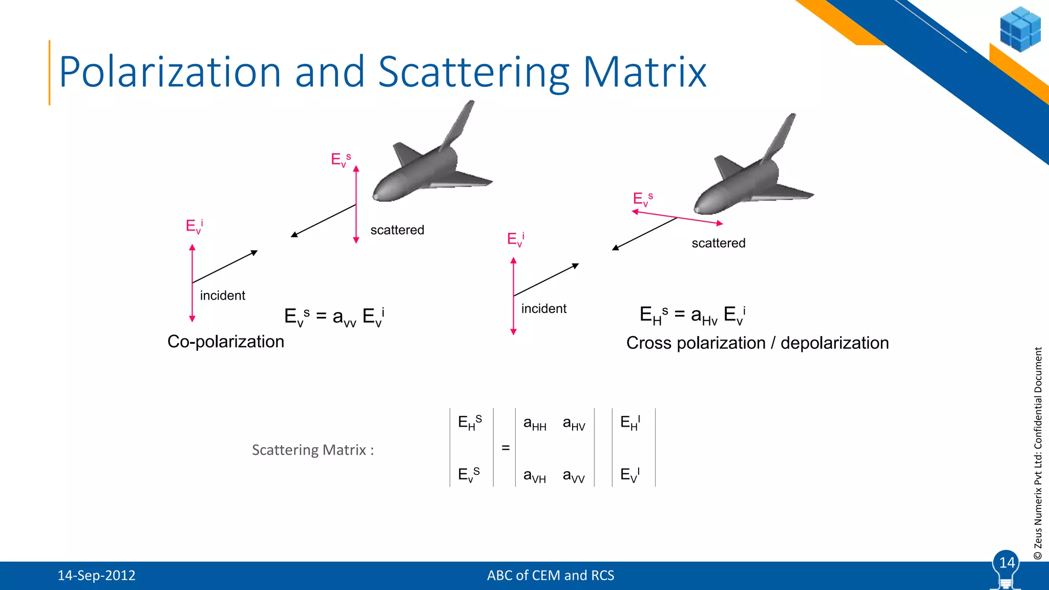
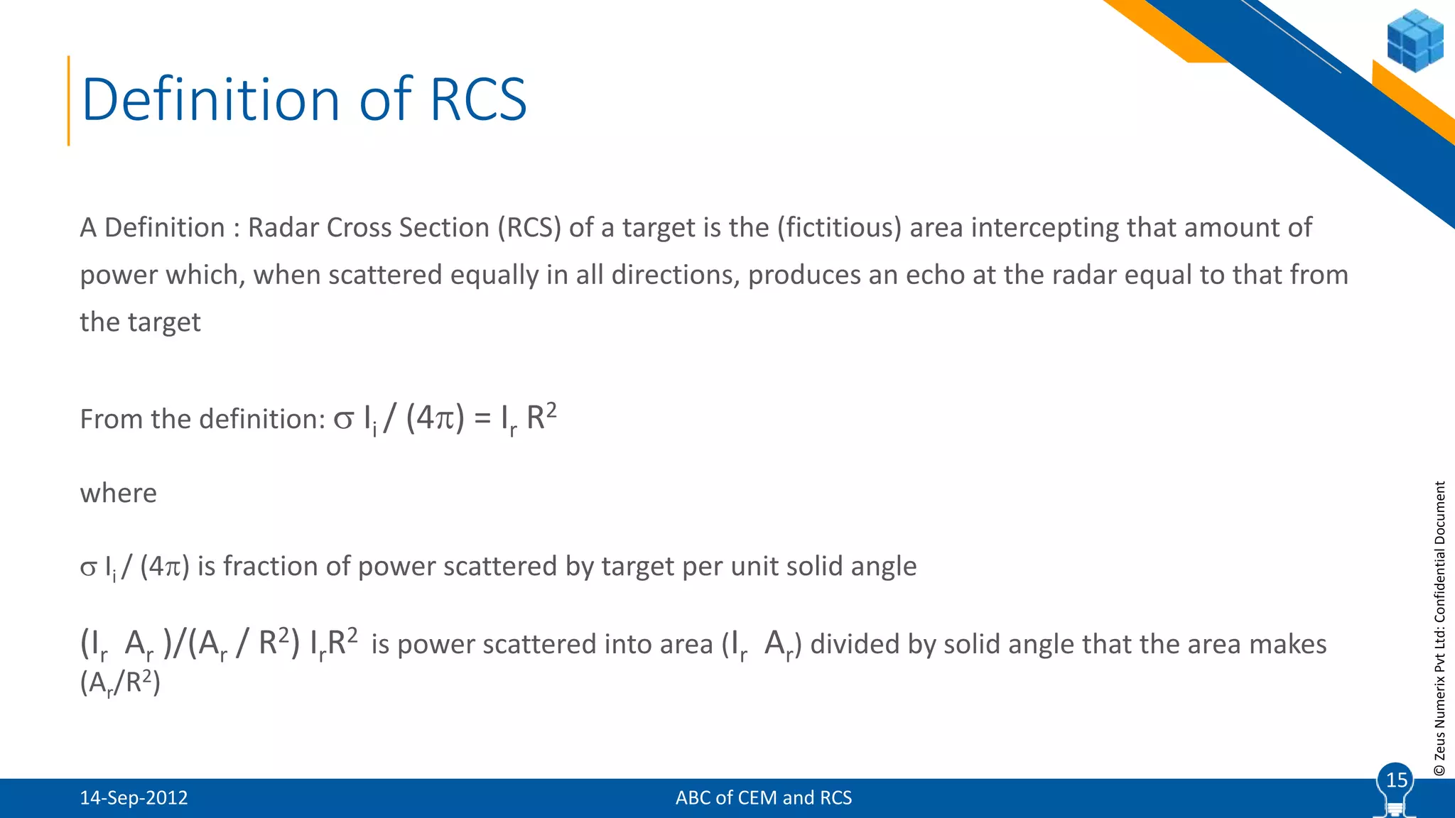
Definition of RCS
Amount of energy scattered by aircraft = energy scattered by sphere
Aircraft scatters different amount of energy in different direction; RCS is different in different directions
= (power reflected by the target per solid angle) / (incident power density / 4)
= limit 4 R2 | Er / Ei | or
R
= limit 4 R2 | Hr / Hi|
R
= limit 4 R2 | Ir / Ii |, I is power density
R
RCS (expressed in db): db = 10 log [( in m2)/(1 m2)]
Equivalent
sphere
16
ABC of CEM and RCS14-Sep-2012](https://image.slidesharecdn.com/01abcofcem-201203084449/75/CEM-Workshop-Lectures-1-11-ABC-of-CEM-and-RCS-16-2048.jpg)
![18
©ZeusNumerixPvtLtd:ConfidentialDocument
Power density at the target (St )
(Psource Gtransmission_antenna) / (4 Rsource-to-target
2), where
Psource = Power transmitted by source radar &
Gtransmission_antenna = gain of the transmitting antenna
Power received by target (Pincident )
= Ssource = (Psource Gtransmission_antenna ) / (4R2
source-to-target), where
= surface area of target
For (PEC) perfectly electrical conductor, the entire power is scattered. If the scattered
energy is isotropic (not a function of the direction), then scattered energy by receiving
radar (Sscattered)
Sscattered = Pincident / (4R2
target-to-receiver) = (Ps Gs )/[(4R2
source-to-target)(4R2
target-to-receiver)]
Range for Given RCS Value
18
ABC of CEM and RCS14-Sep-2012](https://image.slidesharecdn.com/01abcofcem-201203084449/75/CEM-Workshop-Lectures-1-11-ABC-of-CEM-and-RCS-18-2048.jpg)

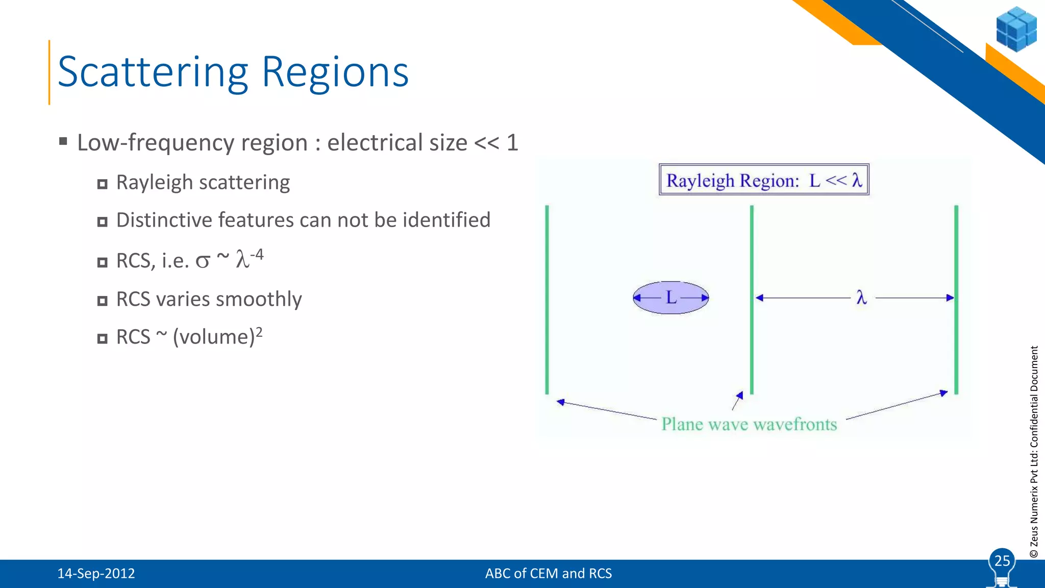


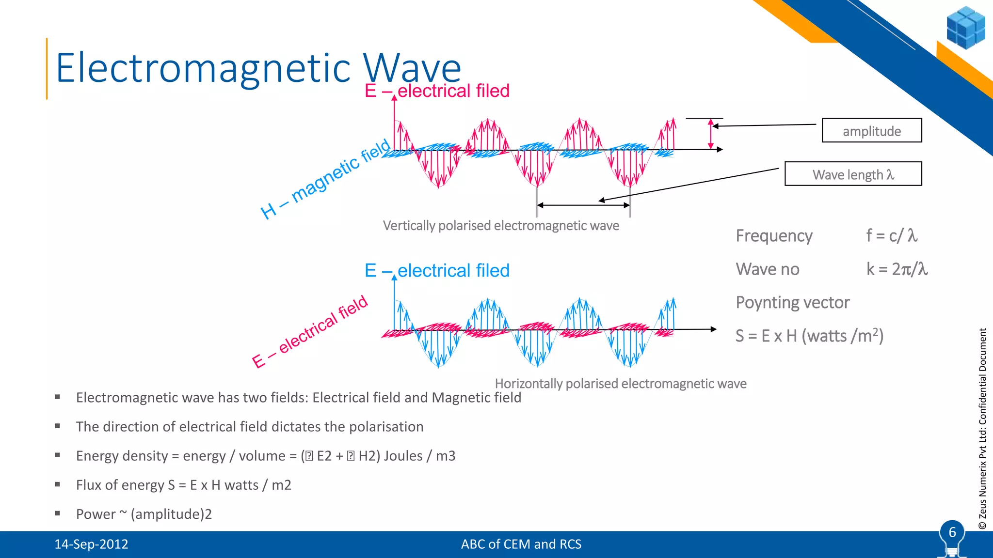
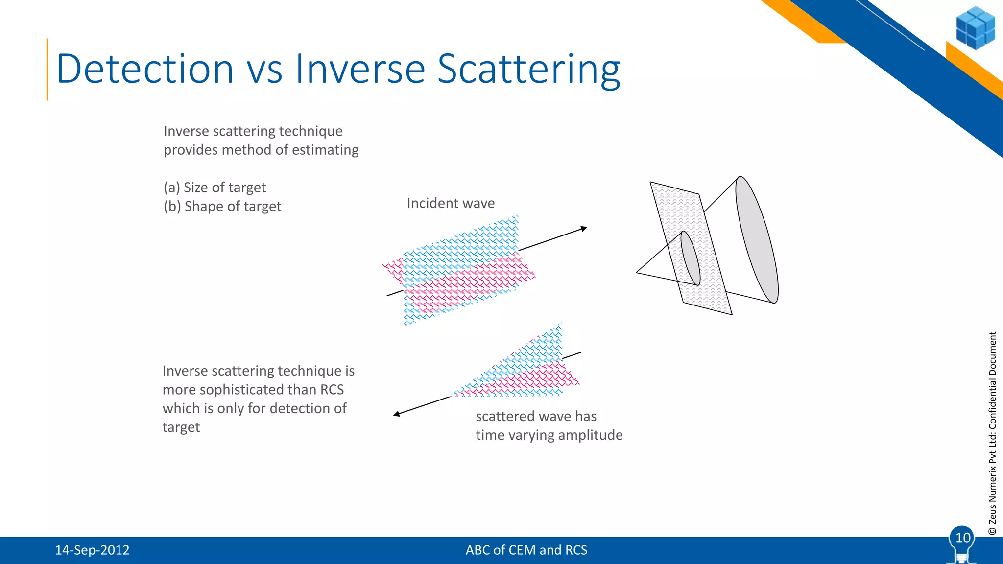
This document provides an introduction to computational electromagnetics (CEM) and predicting radar cross section (RCS) of aerial targets. It covers basics of electromagnetic waves, stealth technologies, RCS of simple shapes and aircraft, factors affecting RCS, and demonstrations for calculating RCS. The training is intended for beginners to understand foundations and methods of RCS prediction, but not for developing own applications or using proprietary software.


