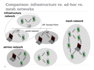
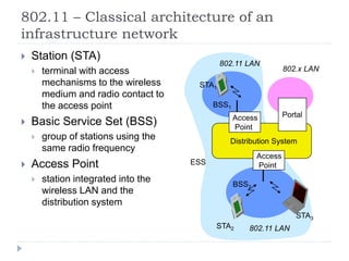
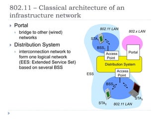
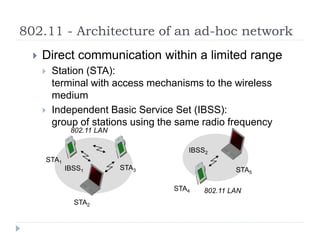
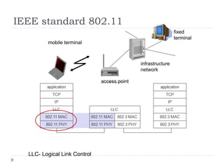
Wireless LAN technologies include WiFi (802.11 standards) and personal wireless networks like Bluetooth. 802.11 defines infrastructure networks with access points connected to wired networks, and ad-hoc networks without infrastructure. Key aspects of 802.11 include CSMA/CA medium access, frame formats, and physical layer standards for radio frequencies (802.11a/b/g/n) and infrared (now obsolete). Wireless networks offer mobility and flexibility compared to wired networks but have lower bandwidth and can be affected by interference.

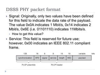
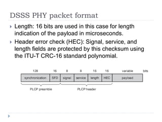
![Mobile Communication Technology
according to IEEE (examples)
Local wireless networks
WLAN 802.11
802.11a
802.11b
802.11i/e/…/n/…/z/az
802.11g
WiFi
802.11h
Personal wireless nw
WPAN 802.15
802.15.4
802.15.1
802.15.2
Bluetooth
802.15.4a/b/c/d/e/f/g…q/r/s
ZigBee
802.15.3
Wireless distribution networks
WMAN 802.16 (Broadband Wireless Access)
[hist.: 802.20 (Mobile Broadband Wireless Access)]
802.16e (addition to .16 for mobile devices)
+ Mobility
WiMAX
802.15.3b/c…e
802.15.5, .6 (WBAN), …](https://image.slidesharecdn.com/3-240225064604-ad26b018/85/3-Introduction-Wireless-Local-Area-Networks-ppt-2-320.jpg)