Downloaded 1,477 times

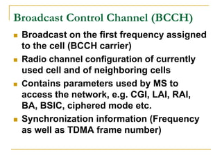
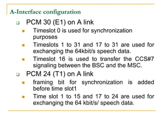
![Multiplexing Technique
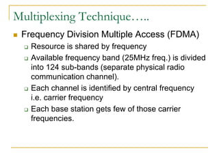
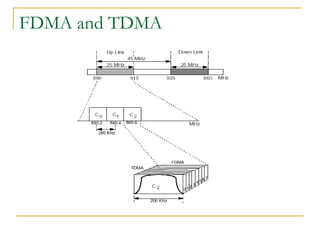
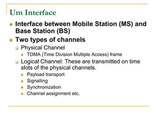
Sharing of scarce transport medium resource by use
of a fixed partitioning between several users. GSM
standard has two simultaneous multiplexing
techniques.
Time Division Multiple Access (TDMA)
Resource is shared by time
Each channel is divided into timeslots, each conversation
uses one timeslot.
Many conversations are multiplexed into a single channel.
GSM standard divides each channel (carrier frequency)
into bursts [0.577 ms]. 8 such bursts are a frame.](https://image.slidesharecdn.com/gsminterfaces-120726110351-phpapp01/85/Gsm-interfaces-10-320.jpg)
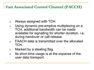
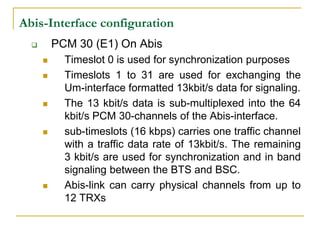
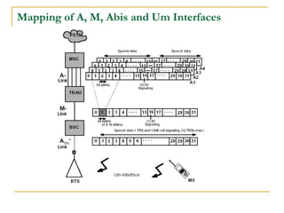

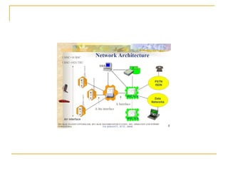
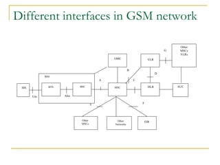
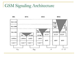
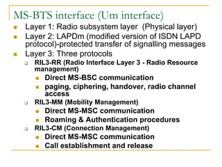
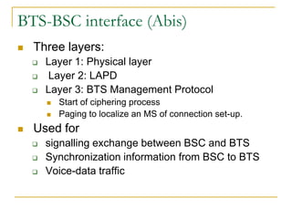
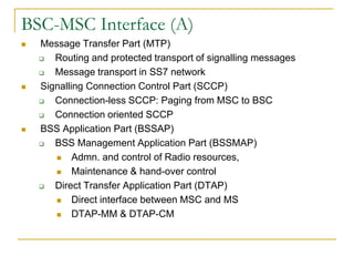
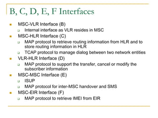
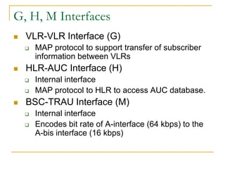
This document summarizes the various interfaces in a GSM network and their functions. It describes: - The MS-BTS interface (Um interface) and its layers and protocols. - The BTS-BSC interface (Abis interface) and its layers. - The BSC-MSC interface (A interface) and its protocols for administration and control of radio resources. - Other interfaces like MSC-VLR (B), MSC-HLR (C), VLR-HLR (D), MSC-MSC (E), MSC-EIR (F), VLR-VLR (G), HLR-AUC (H), and BSC-TR