Downloaded 254 times

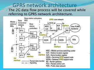
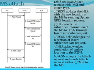
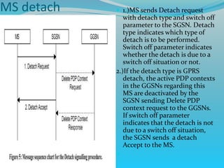
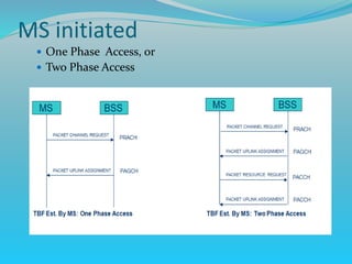
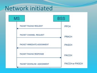
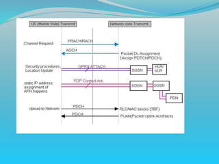
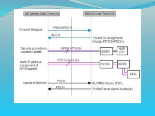

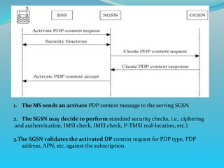
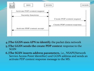


The document discusses GPRS network architecture and processes. It describes how a mobile station (MS) attaches to and detaches from the GPRS network by communicating with the SGSN and HLR. It also describes how a temporary block flow (TBF) is established to enable data transfer between the MS and network. Additionally, it outlines how a packet data protocol (PDP) context is activated and deactivated to manage the subscriber's data session.