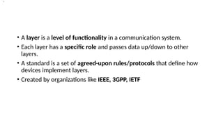
• A layeris a level of functionality in a communication system.
• Each layer has a specific role and passes data up/down to other
layers.
• A standard is a set of agreed-upon rules/protocols that define how
devices implement layers.
• Created by organizations like IEEE, 3GPP, IETF
•.
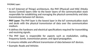
PHY/MAC Layer:
• InIoT (Internet of Things) architecture, the PHY (Physical) and MAC (Media
Access Control) layers refer to the lower layers of the communication stack
responsible for establishing and managing the physical connectivity and data
transmission between IoT devices.
• PHY Layer: The PHY layer is the lowest layer in the IoT communication stack
and deals with the physical transmission of data over the communication
medium.
• It defines the hardware and electrical specifications required for transmitting
and receiving signals.
• The PHY layer is responsible for aspects such as modulation, coding,
frequency bands, transmission power, and signal propagation.
• It ensures reliable and efficient transmission of data between IoT devices.
• Example: Roads and Vehicles
6.
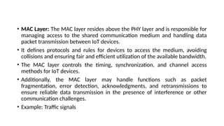
• MAC Layer:The MAC layer resides above the PHY layer and is responsible for
managing access to the shared communication medium and handling data
packet transmission between IoT devices.
• It defines protocols and rules for devices to access the medium, avoiding
collisions and ensuring fair and efficient utilization of the available bandwidth.
• The MAC layer controls the timing, synchronization, and channel access
methods for IoT devices.
• Additionally, the MAC layer may handle functions such as packet
fragmentation, error detection, acknowledgments, and retransmissions to
ensure reliable data transmission in the presence of interference or other
communication challenges.
• Example: Traffic signals
7.
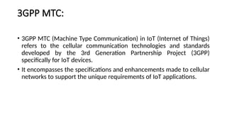
3GPP MTC:
• 3GPPMTC (Machine Type Communication) in IoT (Internet of Things)
refers to the cellular communication technologies and standards
developed by the 3rd Generation Partnership Project (3GPP)
specifically for IoT devices.
• It encompasses the specifications and enhancements made to cellular
networks to support the unique requirements of IoT applications.
8.
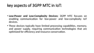
key aspects of3GPP MTC in IoT:
• Low-Power and Low-Complexity Devices: 3GPP MTC focuses on
enabling communication for low-power and low-complexity IoT
devices.
• These devices typically have limited processing capabilities, memory,
and power supply, requiring communication technologies that are
optimized for efficiency and resource conservation.
9.
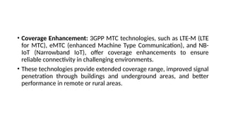
• Coverage Enhancement:3GPP MTC technologies, such as LTE-M (LTE
for MTC), eMTC (enhanced Machine Type Communication), and NB-
IoT (Narrowband IoT), offer coverage enhancements to ensure
reliable connectivity in challenging environments.
• These technologies provide extended coverage range, improved signal
penetration through buildings and underground areas, and better
performance in remote or rural areas.
10.
• Power Efficiency:Power consumption is a critical concern for IoT
devices, many of which operate on battery power.
• 3GPP MTC introduces power-saving features such as extended
discontinuous reception (eDRX) and power saving mode (PSM) to
minimize energy consumption.
• These mechanisms allow IoT devices to enter sleep modes for
extended periods while still maintaining network connectivity.
11.
• Optimized DataRates: 3GPP MTC technologies provide optimized
data rates suitable for IoT applications.
• While they may not offer the high data throughput of traditional
cellular networks, they provide sufficient bandwidth for transmitting
small amounts of data, periodic sensor readings, and control
messages required by IoT devices.
• Quality of Service (QoS): 3GPP MTC supports differentiated QoS for
different types of IoT applications.
• QoS parameters can be adjusted to meet the specific requirements of
diverse IoT use cases.
12.
• Security andAuthentication: 3GPP MTC includes robust security
mechanisms to protect IoT device communications. It utilizes
encryption, authentication, and access control measures to ensure
the confidentiality and integrity of data transmitted over the cellular
network.
• Integration with IoT Platforms: 3GPP MTC technologies are designed
to seamlessly integrate with IoT platforms and cloud services. They
provide standardized protocols and interfaces for data exchange,
device management, and integration with higher-level IoT systems.
13.
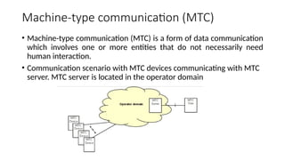
Machine-type communication (MTC)
•Machine-type communication (MTC) is a form of data communication
which involves one or more entities that do not necessarily need
human interaction.
• Communication scenario with MTC devices communicating with MTC
server. MTC server is located in the operator domain
14.
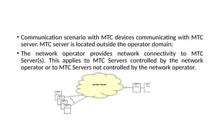
• Communication scenariowith MTC devices communicating with MTC
server. MTC server is located outside the operator domain:
• The network operator provides network connectivity to MTC
Server(s). This applies to MTC Servers controlled by the network
operator or to MTC Servers not controlled by the network operator.
15.
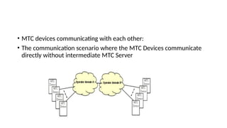
• MTC devicescommunicating with each other:
• The communication scenario where the MTC Devices communicate
directly without intermediate MTC Server
16.
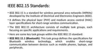
IEEE 802.15 Standards:
•IEEE 802.15 is a standard for wireless personal area networks (WPANs)
developed by the Institute of Electrical and Electronics Engineers (IEEE).
• It defines the physical layer (PHY) and medium access control (MAC)
layer specifications for short-range wireless communication.
• The IEEE 802.15 architecture consists of multiple task groups, each
focusing on specific applications and requirements.
• Here are some key task groups within the IEEE 802.15 standard:
• IEEE 802.15.1 (Bluetooth): This task group defines the specifications for
Bluetooth wireless technology, which enables short-range
communication between devices such as mobile phones, laptops, and
peripherals.
17.
• IEEE 802.15.4:This task group specifies the PHY and MAC layers for low-
rate wireless personal area networks (LR-WPANs). It is commonly used in
applications like home automation, industrial control, and wireless sensor
networks. The most well-known standard built on IEEE 802.15.4 is Zigbee.
• IEEE 802.15.3: This task group focuses on high-rate wireless personal area
networks (HR-WPANs). It defines the PHY and MAC layers for applications
that require higher data rates, such as streaming multimedia.
• IEEE 802.15.6: This task group concentrates on wireless body area
networks (WBANs). It addresses the specific requirements of medical,
healthcare, and fitness applications by defining the PHY and MAC layers
suitable for wearable and implantable devices.
18.
• IEEE 802.15.7:This task group defines the PHY and MAC layers for
visible light communication (VLC).
• It enables communication using light-emitting diodes (LEDs) and is
often used for indoor positioning, smart lighting, and other
applications.
19.
IEEE 802.15.4
• IEEE802.15.4: This also called a LR-WPAN protocol
• IEEE 802.15.4 is a subgroup of features that refers to physical and
medium access control layers that can support ZigBee and 6LoWPAN
upper.
• Simple and flexible protocol stack, low cost, low energy consumption,
short-range operation, reliable data transfer, and ease of operation
20.
IEEE 802.15.4 (PhysicalLayer)
• The 802.15.4 standard supports an extensive number of PHY options
that range from
• 2.4 GHz to sub-GHz frequencies in ISM( Industrial, scientific, Medical)
bands.( frequency ranges reserved for unlicensed use in various
applications).
• The original IEEE 802.15.4-2003 standard specified only three PHY
options based on direct sequence spread spectrum (DSSS)
modulation.
• DSSS is a modulation technique in which a signal is intentionally
spread in the frequency domain, resulting in greater bandwidth.
21.
The original physicallayer transmission options were as follows:
• 2.4 GHz, 16 channels, with a data rate of 250 kbps
• 915 MHz, 10 channels, with a data rate of 40 kbps
• 868 MHz, 1 channel, with a data rate of 20 kbps
• Only the 2.4 GHz band operates worldwide.
• The 915 MHz band operates mainly in North and South America, and
the 868 MHz frequencies are used in Europe, the Middle East, and
Africa.
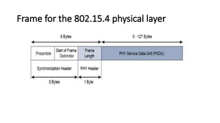
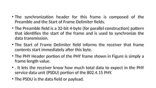
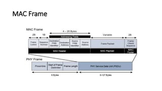
• The synchronizationheader for this frame is composed of the
Preamble and the Start of Frame Delimiter fields.
• The Preamble field is a 32-bit 4-byte (for parallel construction) pattern
that identifies the start of the frame and is used to synchronize the
data transmission.
• The Start of Frame Delimiter field informs the receiver that frame
contents start immediately after this byte.
• The PHY Header portion of the PHY frame shown in Figure is simply a
frame length value.
• . It lets the receiver know how much total data to expect in the PHY
service data unit (PSDU) portion of the 802.4.15 PHY.
• The PSDU is the data field or payload.
24.
IEEE 802.15.4 MAClayer
The 802.15.4 MAC layer performs the following tasks:
• Network beaconing for devices acting as coordinators (New devices
use beacons to join an 802.15.4 network)
• PAN association and disassociation by a device
• Device security
• Reliable link communications between two peer MAC entities
25.
The MAC layerachieves these tasks by using various predefined 4
frame types.
• Data frame: Handles all transfers of data
• Beacon frame: Used in the transmission of beacons from a PAN
coordinator
• Acknowledgement frame: Confirms the successful reception of a
frame
• MAC command frame: Responsible for control communication
between devices
• The MACframe is carried as the PHY payload.
• The 802.15.4 MAC frame can be broken down into the MAC Header, MAC
Payload, and MAC Footer fields.
• The MAC Header field is composed of the Frame Control, Sequence
Number and the Addressing fields.
• The Frame Control field defines attributes such as frame type, address- ing
modes, and other control flags.
• The Sequence Number field indicates the sequence identifier for the frame.
• The Addressing field specifies the Source and Destination PAN Identifier
fields as well as the Source and Destination Address fields.
28.
• The MACPayload field varies by individual frame type. For example,
beacon frames have specific fields and payloads related to beacons,
while MAC command frames have different fields present.
• The MAC Footer field is nothing more than a frame check sequence
(FCS). An FCS is a calculation based on the data in the frame that is
used by the receiving side to confirm the integrity of the data in the
frame.
29.
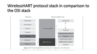
Wireless HART
• WirelessHART is a datalink protocol that operates on the top of IEEE 802.15.4 PHY and
adopts Time Division Multiple Access (TDMA) in its MAC.
• Wireless HART is a wireless communication standard specifically designed for industrial
process automation. It is based on the Highway Addressable Remote Transducer (HART)
protocol, which is widely used in industrial control systems.
• WirelessHART can be considered as the wireless evolution of the highway addressable
remote transducer (HART) protocol.
• It is a license-free protocol, which was developed for networking smart field devices in
industrial environments.
• The lack of wires makes the adaptability of this protocol significantly advantageous over its
predecessor, HART, in industrial settings. By virtue of its highly encrypted communication,
wireless HART is very secure and has several advantages over traditional communication
protocols.
30.
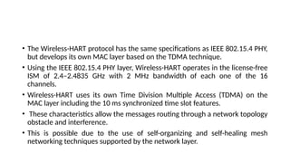
• The Wireless-HARTprotocol has the same specifications as IEEE 802.15.4 PHY,
but develops its own MAC layer based on the TDMA technique.
• Using the IEEE 802.15.4 PHY layer, Wireless-HART operates in the license-free
ISM of 2.4–2.4835 GHz with 2 MHz bandwidth of each one of the 16
channels.
• Wireless-HART uses its own Time Division Multiple Access (TDMA) on the
MAC layer including the 10 ms synchronized time slot features.
• These characteristics allow the messages routing through a network topology
obstacle and interference.
• This is possible due to the use of self-organizing and self-healing mesh
networking techniques supported by the network layer.
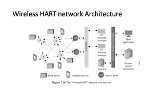
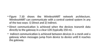
• Figure 7.10shows the WirelessHART network architecture.
WirelessHART can communicate with a central control system in any
of the two ways: 1) Direct and 2) indirect.
• Direct communication is achieved when the devices transmit data
directly to the gateway in a clear LOS (typically 250 m).
• Indirect communication is achieved between devices in a mesh and a
gateway when messages jump from device to device until it reaches
the gateway.
33.
• The HARTencompasses the most number of field devices
incorporated in any field network.
• WirelessHART makes device placements more accessible and cheaper,
such as the top of a reaction tank, inside a pipe, or widely separated
warehouses.
34.
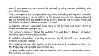
• use ofinterference-prone channels is avoided by using channel switching after
every transmission.
• The transmissions are synchronized using 10 ms time-slots. During each time-slot,
all available channels can be utilized by the various nodes in the network, allowing
for the simultaneous propagation of 15 packets through the network, which also
minimizes the risk of collisions between channels.
• A network manager supervises each node in the network and guides them on
when and where to send packets.
• This network manager allows for collision-free and timely delivery of packets
between a source and the destination.
• It updates information regarding neighbors, signal strength, and information
needing a delivery receipt.
• This network manager also decides which nodes transmit, which nodes listen, and
the frequency to be utilized in each time-slot.
• It also handles code-based network security and prevents unauthorized nodes
from joining the network
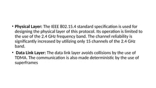
• Physical Layer:The IEEE 802.15.4 standard specification is used for
designing the physical layer of this protocol. Its operation is limited to
the use of the 2.4 GHz frequency band. The channel reliability is
significantly increased by utilizing only 15 channels of the 2.4 GHz
band.
• Data Link Layer: The data link layer avoids collisions by the use of
TDMA. The communication is also made deterministic by the use of
superframes
37.
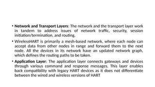
• Network andTransport Layers: The network and the transport layer work
in tandem to address issues of network traffic, security, session
initiation/termination, and routing.
• WirelessHART is primarily a mesh-based network, where each node can
accept data from other nodes in range and forward them to the next
node. All the devices in its network have an updated network graph,
which defines the routing paths to be taken.
• Application Layer: The application layer connects gateways and devices
through various command and response messages. This layer enables
back compatibility with legacy HART devices as it does not differentiate
between the wired and wireless versions of HART
38.
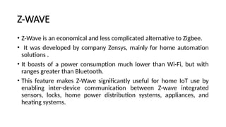
Z-WAVE
• Z-Wave isan economical and less complicated alternative to Zigbee.
• It was developed by company Zensys, mainly for home automation
solutions .
• It boasts of a power consumption much lower than Wi-Fi, but with
ranges greater than Bluetooth.
• This feature makes Z-Wave significantly useful for home IoT use by
enabling inter-device communication between Z-wave integrated
sensors, locks, home power distribution systems, appliances, and
heating systems.
39.
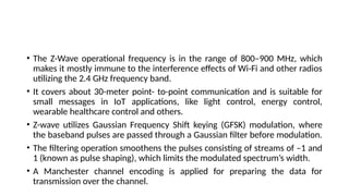
• The Z-Waveoperational frequency is in the range of 800–900 MHz, which
makes it mostly immune to the interference effects of Wi-Fi and other radios
utilizing the 2.4 GHz frequency band.
• It covers about 30-meter point- to-point communication and is suitable for
small messages in IoT applications, like light control, energy control,
wearable healthcare control and others.
• Z-wave utilizes Gaussian Frequency Shift keying (GFSK) modulation, where
the baseband pulses are passed through a Gaussian filter before modulation.
• The filtering operation smoothens the pulses consisting of streams of –1 and
1 (known as pulse shaping), which limits the modulated spectrum’s width.
• A Manchester channel encoding is applied for preparing the data for
transmission over the channel.
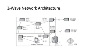
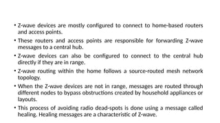
• Z-wave devicesare mostly configured to connect to home-based routers
and access points.
• These routers and access points are responsible for forwarding Z-wave
messages to a central hub.
• Z-wave devices can also be configured to connect to the central hub
directly if they are in range.
• Z-wave routing within the home follows a source-routed mesh network
topology.
• When the Z-wave devices are not in range, messages are routed through
different nodes to bypass obstructions created by household appliances or
layouts.
• This process of avoiding radio dead-spots is done using a message called
healing. Healing messages are a characteristic of Z-wave.
42.
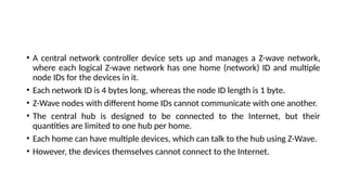
• A centralnetwork controller device sets up and manages a Z-wave network,
where each logical Z-wave network has one home (network) ID and multiple
node IDs for the devices in it.
• Each network ID is 4 bytes long, whereas the node ID length is 1 byte.
• Z-Wave nodes with different home IDs cannot communicate with one another.
• The central hub is designed to be connected to the Internet, but their
quantities are limited to one hub per home.
• Each home can have multiple devices, which can talk to the hub using Z-Wave.
• However, the devices themselves cannot connect to the Internet.
43.
DASH7
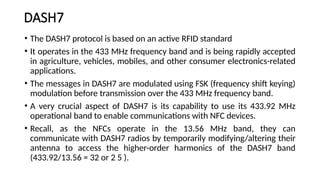
• The DASH7protocol is based on an active RFID standard
• It operates in the 433 MHz frequency band and is being rapidly accepted
in agriculture, vehicles, mobiles, and other consumer electronics-related
applications.
• The messages in DASH7 are modulated using FSK (frequency shift keying)
modulation before transmission over the 433 MHz frequency band.
• A very crucial aspect of DASH7 is its capability to use its 433.92 MHz
operational band to enable communications with NFC devices.
• Recall, as the NFCs operate in the 13.56 MHz band, they can
communicate with DASH7 radios by temporarily modifying/altering their
antenna to access the higher-order harmonics of the DASH7 band
(433.92/13.56 = 32 or 2 5 ).
45.
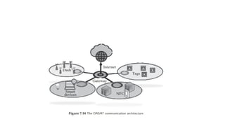
• DASH7 iscapable of very dense deployments, has a low memory
footprint, consumes minuscule power, and considered by many as a
bridge between NFC and IoT communication systems.
• It can also be used to enable tag-to-tag communication without
needing the tags to pass their information through a base station or a
tag reader.
46.
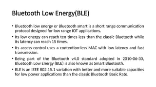
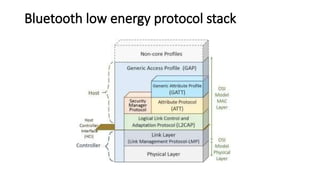
Bluetooth Low Energy(BLE)
•Bluetooth low energy or Bluetooth smart is a short range communication
protocol designed for low range IOT applications.
• Its low energy can reach ten times less than the classic Bluetooth while
its latency can reach 15 times.
• Its access control uses a contention-less MAC with low latency and fast
transmission.
• Being part of the Bluetooth v4.0 standard adopted in 2010-06-30,
Bluetooth Low Energy (BLE) is also known as Smart Bluetooth.
• BLE is an IEEE 802.15.1 variation with better and more suitable capacities
for low power applications than the classic Bluetooth Basic Rate.
47.
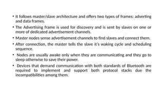
• It followsmaster/slave architecture and offers two types of frames: adverting
and data frames.
• The Advertising frame is used for discovery and is sent by slaves on one or
more of dedicated advertisement channels.
• Master nodes sense advertisement channels to find slaves and connect them.
• After connection, the master tells the slave it’s waking cycle and scheduling
sequence.
• Nodes are usually awake only when they are communicating and they go to
sleep otherwise to save their power.
• Devices that demand communication with both standards of Bluetooth are
required to implement and support both protocol stacks due the
incompatibilities among them.
48.
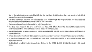
• Star isthe only topology accepted by BLE due the standard definition that does not permit physical link
connections among slave devices.
• Any data exchanged between two slave devices shall pass through the unique master and a slave device
may not be connected to two master units at the same time.
• These premises define the formation of a BLE star pico-net.
• The two main roles of BLE are: controller and host. BLE differs from the classical Bluetooth in the
controller stack that defines the association methods of the devices.
• A slave can belong to only one pico-net during an association lifetime, and is synchronized with only one
master element.
• A Host Controller Interface (HCI) is a communication standard applied between the slave and controller.
• In the Bluetooth Basic Rate, 79 channels are used with a 1 MHz bandwidth to reduce interference with
adjacent channels.
• In Bluetooth Low Energy, the channels are defined in the 2.400– 2.4835 GHz band with a 2 MHz guard
band.
49.
• The energysave handling done at MAC layer can put the slaves in a
sleeping mode by default and waking them periodically through a
Time Division Multiple Access (TDMA) scheme.
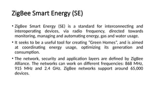
ZigBee Smart Energy(SE)
• ZigBee Smart Energy (SE) is a standard for interconnecting and
interoperating devices, via radio frequency, directed towards
monitoring, managing and automating energy, gas and water usage.
• It seeks to be a useful tool for creating “Green Homes”, and is aimed
at coordinating energy usage, optimizing its generation and
consumption.
• The network, security and application layers are defined by ZigBee
Alliance. The networks can work on different frequencies: 868 MHz,
915 MHz and 2.4 GHz. ZigBee networks support around 65,000
devices.
52.
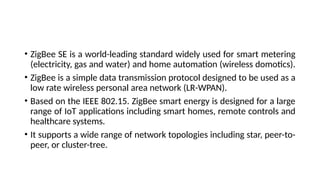
• ZigBee SEis a world-leading standard widely used for smart metering
(electricity, gas and water) and home automation (wireless domotics).
• ZigBee is a simple data transmission protocol designed to be used as a
low rate wireless personal area network (LR-WPAN).
• Based on the IEEE 802.15. ZigBee smart energy is designed for a large
range of IoT applications including smart homes, remote controls and
healthcare systems.
• It supports a wide range of network topologies including star, peer-to-
peer, or cluster-tree.
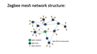
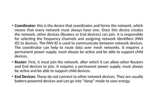
• Coordinator: thisis the device that coordinates and forms the network, which
means that every network must always have one. Once this device creates
the network, other devices (Routers or End devices) can join. It is responsible
for selecting the frequency channels and assigning network identifiers (PAN
ID) to devices. The PAN ID is used to communicate between network devices.
The coordinator can help to route data over mesh networks. It requires a
permanent power supply, must always be active and be able to support child
devices.
• Router: First, it must join the network, after which it can allow other Routers
and End devices to join. It requires a permanent power supply, must always
be active and be able to support child devices.
• End Devices: These do not connect to other network devices. They are usually
battery-powered devices and can go into “sleep” mode to save energy.
55.
• Reason forZigBee Smart Energy
• ZigBee SE provides service providers and power distributors with a simple wireless
access network within homes (Home Area Network, or HAN).
• Smart Energy offers these groups and their customers the possibility of
communicating with each other directly in order to control smart applications (e.g.,
thermostats and other devices used to control high energy use in the home).
• Having access to customers’ instantaneous consumption enables power distributors
to more efficiently manage the electricity smart grid (generation and distribution).
Furthermore, customers can receive real-time information on their energy use
through devices installed inside the home, as well as by accessing the HAN through
the services provided by energy distributors and/or service providers.