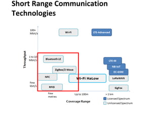
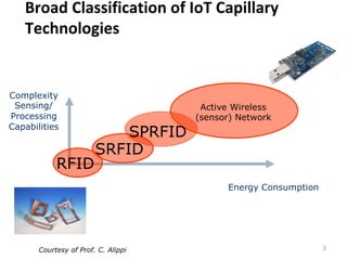
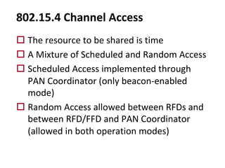
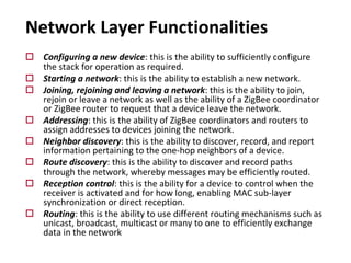
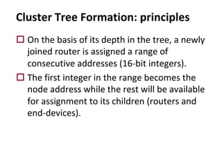
1) The document discusses various short range communication technologies and protocols for IoT devices, including Zigbee and 6LoWPAN.
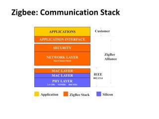
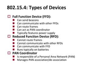
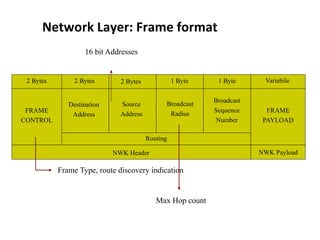
2) It provides an overview of the Zigbee communication stack, which is based on the IEEE 802.15.4 standard and includes physical, MAC, network and application layers.
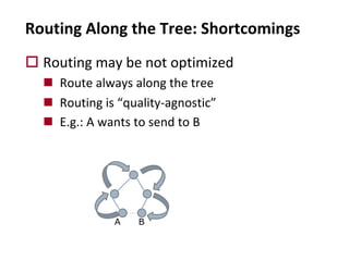
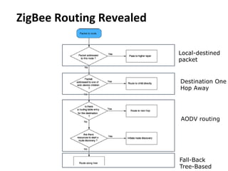
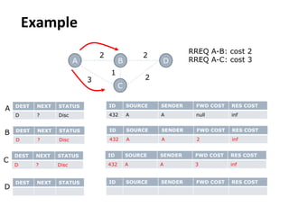
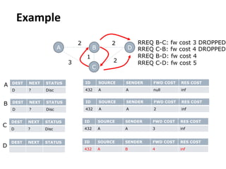
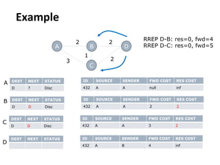
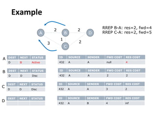
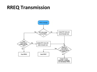
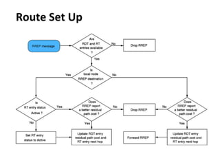
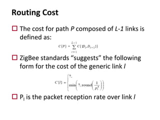
3) The Zigbee network layer supports tree-based routing along with an implementation of the AODV routing protocol to allow for more optimized routing in some cases.

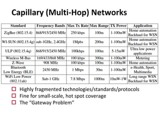
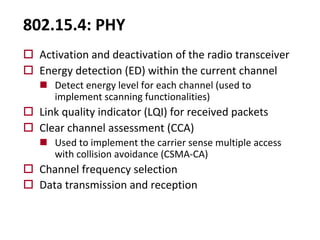
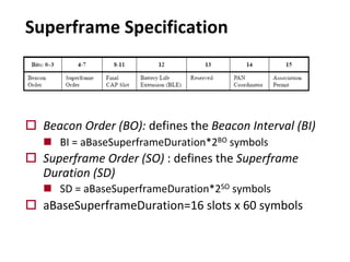
![o Preamble: to achieve synchronization
o SFD: frame delimiter
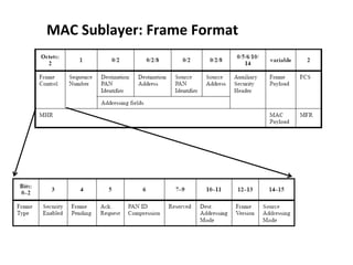
o Frame Length: length (in octets) of the PHY
payload
n For MAC data frames in the range of [9-127]
PHY: PDU format](https://image.slidesharecdn.com/8-zigbee2-230816140813-3d3d7f22/85/8-ZigBee-2-pdf-18-320.jpg)
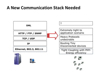
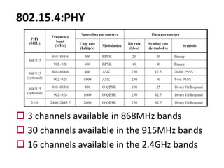
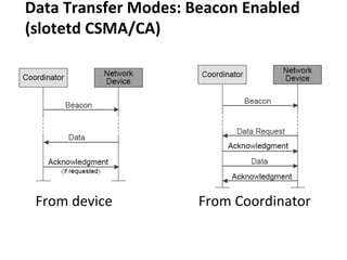
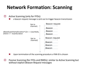
![Beacon Enabled: functional description
o Beacon Enabled
o Frame Length: from 15[ms] to 252[s]
(15.38ms*2n where 0 £ n £ 14)
o RFD associated to PAN coordinator are aligned with
the frame structure
o Random access through CSMA/CA in CAP
o Guranteed Time Slot statically assigned by PAN
coordinator through beacons
GTS GTS Inactive
Beacon Beacon
CAP CFP
0 1 2 3 4 5 6 7 8 9 10 11 12 13 15
14](https://image.slidesharecdn.com/8-zigbee2-230816140813-3d3d7f22/85/8-ZigBee-2-pdf-22-320.jpg)
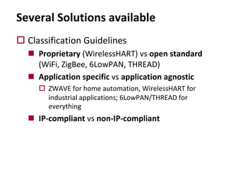
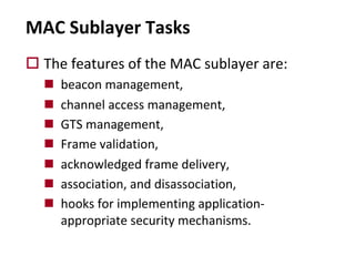
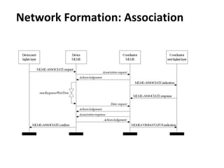
![CSMA Procedure at a Glance
o A transmitting node delays for a random
number of backoff periods in [0, 2BE-1]
o If clear channel assessments (CCA) is idle for
CW consecutive backoff periods, the node
starts the transmission and waits for an ACK.
o If the channel is busy, the exponent BE and the
number of backoff attempts, NB, are
incremented and the procedure is repeated
o After “too many” (NBmax) failed retries, the
packet is discarded](https://image.slidesharecdn.com/8-zigbee2-230816140813-3d3d7f22/85/8-ZigBee-2-pdf-24-320.jpg)
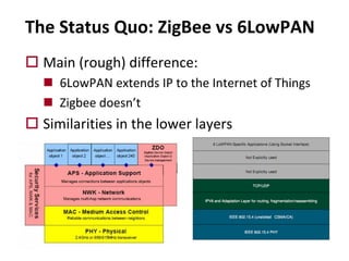
![o The size A(d) of the range of addresses assigned to a
router node at depth d < Lm is defined by:
o Nodes at depth Lm and end-devices are assigned a
single address.
o Simple Assignment Rule:
o A mote at level d is assigned addresses in range [x,x + A(d)-1]
o It will assign
n [x+(i-1)A(d+1)+1,x+iA(d+1)] to its i-th router child (1£i
£Rm)
n x+RmA(d+1)+j to its jth end-device child (1 £j £Dm).
Address Assignment Rule](https://image.slidesharecdn.com/8-zigbee2-230816140813-3d3d7f22/85/8-ZigBee-2-pdf-41-320.jpg)
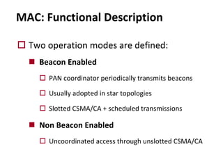
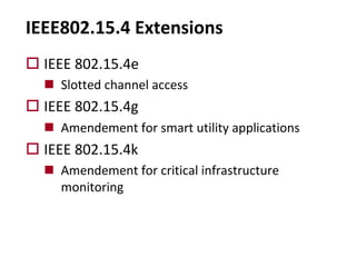
![An Example
o Address allocations
for Rm = 2, Dm = 2
and Lm= 3.
n A(2)=2+2+1=5
n A(1)=1+2+2A(2)=13
n A(0)=1+2+2A(1)=29
n PAN Coordinator
can assign
addresses in the
range [0,28]](https://image.slidesharecdn.com/8-zigbee2-230816140813-3d3d7f22/85/8-ZigBee-2-pdf-42-320.jpg)


![Zigbee technology [autosaved]](https://cdn.slidesharecdn.com/ss_thumbnails/zigbeetechnologyautosaved-140716030459-phpapp02-thumbnail.jpg?width=640&height=640&fit=bounds)