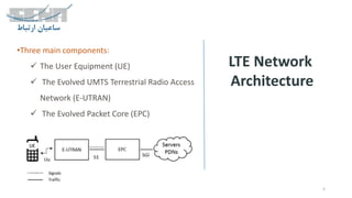
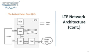
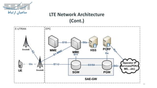
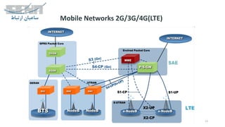
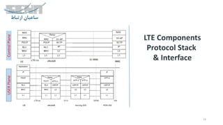
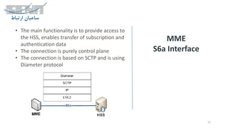
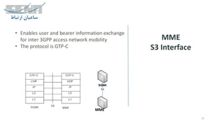
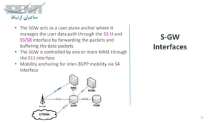
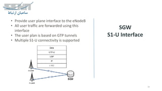
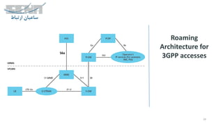
The document provides an overview of LTE network architecture, detailing its three main components: User Equipment (UE), Evolved UMTS Terrestrial Radio Access Network (E-UTRAN), and Evolved Packet Core (EPC). It outlines the functions of various modules and interfaces within these components, including user data management, signaling, and roaming architecture. The document serves as a comprehensive guide for understanding the structure and operations of LTE networks.
LTE Network
Architecture
5
•Three maincomponents:
The User Equipment (UE)
The Evolved UMTS Terrestrial Radio Access
Network (E-UTRAN)
The Evolved Packet Core (EPC)
UE
6.
LTE Network
Architecture
(Cont.)
6
• TheUser Equipment (UE), comprised of the
following important modules:
o Mobile Termination (MT) : handles all the
communication functions
o Terminal Equipment (TE) : terminates the data
streams
o Universal Integrated Circuit Card (UICC) : known as
the SIM card for LTE equipment's. It runs an
application known as the Universal Subscriber
Identity Module (USIM)
7.
LTE Network
Architecture
(Cont.)
7
• TheE-UTRAN (access network):
o Handles the radio communications between the
mobile and the evolved packet core
o Just one component, the evolved base stations,
called eNodeB or eNB
o Each eBN connects with the EPC by means of the
S1 interface
o It can also be connected to nearby base stations by
the X2 interface, which is mainly used for signalling
and packet forwarding during handover
LTE Network
Architecture
(Cont.)
9
• TheEvolved Packet Core (EPC): core network, is
included some components:
o The Home Subscriber Server (HSS): a central
database that contains information about all the
network operator's subscribers
o The Packet Data Network (PDN) Gateway (P-GW):
communicates with the packet data networks PDN,
using SGi interface
o The serving gateway (S-GW): acts as a router, and
forwards data between the base station and the
PDN gateway
10.
LTE Network
Architecture
(Cont.)
10
o Themobility management entity (MME): controls
the high-level operation of the mobile by means of
signaling messages and HSS
o The Policy Control and Charging Rules Function
(PCRF): is responsible for policy control decision-
making, as well as for controlling the flow-based
charging functionalities in the Policy Control
Enforcement Function (PCEF), which resides in the
P-GW
15
eNodeB
X2 Interface
User PlaneControlPlane
• The X2 interface main function is to provide an E-
UTRAN handover without the involvement of the
Core network
• The control plan is based on SCTP and User plane is
based on UDP
16.
16
MME
Interfaces
• The MMEprovides the main roaming
architecture
• It provides session management through S1-
MME interface to eNodeB
• The MME controls the user data plane through
S11 interface
• The MME provides the mobility management
function through S10 interface
• It does user authentication through S6a interface
that is connected to HSS
• The MME provides an integration point with
2G/3G core SGSN via S3 interface
17.
17
MME
Protocol Stack
• TheMME mobility and session management
functionalities is implemented on NAS (Non-
Access-Stratum)
18.
18
MME
S1-AP Interface
• Itprovides a Control interface to the eNodeB
• It’s based on SCTP
• It’s transport for NAS
• It’s a many to many interface
eNodeB
19.
19
MME
S11 Interface
• Itprovides a Control interface between MME
and SGW (SAE GW)
• The protocol is GTP-C
• It’s many to many
20.
20
MME
S10 Interface
• Themain functionality is to connect the MME
with the neighbor MME
• It supports only control plane
• The protocol is GTP-C
21.
21
MME
S6a Interface
• Themain functionality is to provide access to
the HSS, enables transfer of subscription and
authentication data
• The connection is purely control plane
• The connection is based on SCTP and is using
Diameter protocol
22.
22
MME
S3 Interface
• Enablesuser and bearer information exchange
for inter 3GPP access network mobility
• The protocol is GTP-C
MME
23.
23
S-GW
Interfaces
• The SGWacts as a user plane anchor where it
manages the user data path through the S1-U and
S5/S8 interface by forwarding the packets and
buffering the data packets
• The SGW is controlled by one or more MME through
the S11 interface
• Mobility anchoring for inter-3GPP mobility via S4
Interface
24.
24
SGW
S1-U Interface
• Provideuser plane interface to the eNodeB
• All user traffic are forwarded using this
interface
• The user plan is based on GTP tunnels
• Multiple S1-U connectivity is supported
25.
25
SGW
S5/S8 Interface
• Themain functionality is to forward traffic
between S –GW and P-GW
• S5 is standardized for local network and S8 is
standardized for roaming
• Control and user plane are under two
different protocol stacks GTP and PMIPv6
26.
26
SGW
S4 Interface
• Itprovides related control and anchoring for
inter-3GPP mobility
• The Protocol is GTP-C
27.
27
SGW
SGi Interface
• TheSGi interface connects the PGW to a
external network (PDN)
• Packet data network may be an operator
external public or private packet data
network or an intra operator packet data
network, IMS, …
28.
28
PCRF
Interfaces
• The PCRFcontrols the main policies assigned
per subscriber
• Provide a QoS policy and charging rules
through the Gx interface
• Provide a Data Network interface through the
Rx+
• Connection between local and roaming PCRF
through S9 interface
• It’s based on Diameter protocol