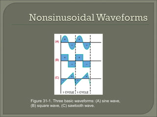
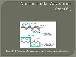
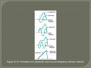
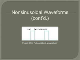
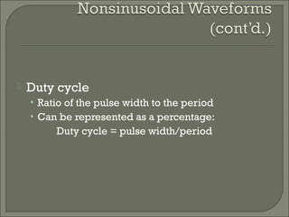
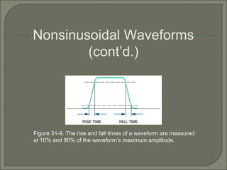
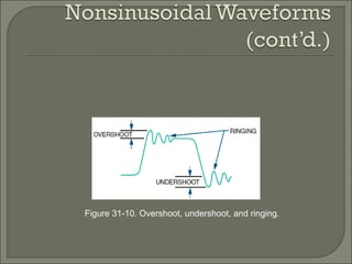
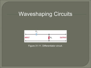
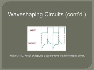
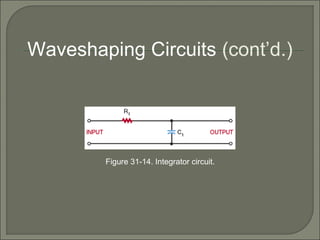
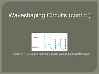
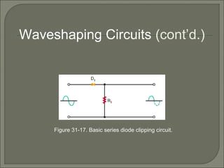
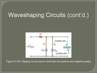
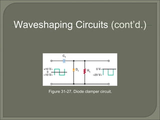
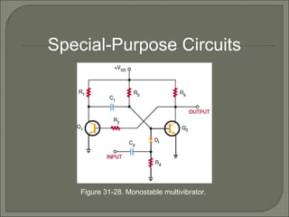
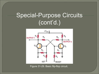
Waveshaping Circuits
Figure 31-1. Three basic waveforms: (A) sine wave,
(B) square wave, (C) sawtooth wave.
Figure 31-4. Formation of a square wave by the frequency domain method.
Figure 31-5. Formation of a sawtooth wave by the frequency domain method.
Figure 31-8. Pulse width of a waveform.
Nonsinusoidal Waveforms
(cont’d.)
 Duty cycle
• Ratio of the pulse width to the period
• Can be represented as a percentage:
Duty cycle = pulse width/period
Figure 31-9. The rise and fall times of a waveform are measured
at 10% and 90% of the waveform’s maximum amplitude.
Nonsinusoidal Waveforms
(cont’d.)
Figure 31-10. Overshoot, undershoot, and ringing.
Figure 31-11. Differentiator circuit.
Waveshaping Circuits
Figure 31-12. Result of applying a square wave to a differentiator circuit.
Waveshaping Circuits (cont’d.)
Figure 31-14. Integrator circuit.
Waveshaping Circuits (cont’d.)
Figure 31-15. Result of applying a square wave to an integrator circuit.
Waveshaping Circuits (cont’d.)
Figure 31-17. Basic series diode clipping circuit.
Waveshaping Circuits (cont’d.)
Figure 31-25. Clipping circuit used to limit both the positive and negative peaks.
Waveshaping Circuits (cont’d.)
Figure 31-27. Diode clamper circuit.
Waveshaping Circuits (cont’d.)
Figure 31-28. Monostable multivibrator.
Special-Purpose Circuits
Figure 31-29. Basic flip-flop circuit.
Special-Purpose Circuits
(cont’d.)
 Waveforms can be changed from one
shape to another using electronic circuits
 The frequency domain concept
• All periodic waveforms are made of sine waves
 Key concepts introduced in the chapter:
• Pulse width, duty cycle, rise and fall time,
undershoot, overshoot, and ringing
 An RC circuit can be used to change the
shape of a complex waveform
 A monostable multivibrator (one-shot
multivibrator) produces one output pulse
for each input pulse
 Bistable multivibrators have two stable
states and are called flip-flops

waveshaping ckts

  • 1.
  • 2.
    Figure 31-1. Threebasic waveforms: (A) sine wave, (B) square wave, (C) sawtooth wave.
  • 3.
    Figure 31-4. Formationof a square wave by the frequency domain method.
  • 4.
    Figure 31-5. Formationof a sawtooth wave by the frequency domain method.
  • 5.
    Figure 31-8. Pulsewidth of a waveform. Nonsinusoidal Waveforms (cont’d.)
  • 6.
     Duty cycle •Ratio of the pulse width to the period • Can be represented as a percentage: Duty cycle = pulse width/period
  • 7.
    Figure 31-9. Therise and fall times of a waveform are measured at 10% and 90% of the waveform’s maximum amplitude. Nonsinusoidal Waveforms (cont’d.)
  • 8.
    Figure 31-10. Overshoot,undershoot, and ringing.
  • 9.
    Figure 31-11. Differentiatorcircuit. Waveshaping Circuits
  • 10.
    Figure 31-12. Resultof applying a square wave to a differentiator circuit. Waveshaping Circuits (cont’d.)
  • 11.
    Figure 31-14. Integratorcircuit. Waveshaping Circuits (cont’d.)
  • 12.
    Figure 31-15. Resultof applying a square wave to an integrator circuit. Waveshaping Circuits (cont’d.)
  • 13.
    Figure 31-17. Basicseries diode clipping circuit. Waveshaping Circuits (cont’d.)
  • 14.
    Figure 31-25. Clippingcircuit used to limit both the positive and negative peaks. Waveshaping Circuits (cont’d.)
  • 15.
    Figure 31-27. Diodeclamper circuit. Waveshaping Circuits (cont’d.)
  • 16.
    Figure 31-28. Monostablemultivibrator. Special-Purpose Circuits
  • 17.
    Figure 31-29. Basicflip-flop circuit. Special-Purpose Circuits (cont’d.)
  • 18.
     Waveforms canbe changed from one shape to another using electronic circuits  The frequency domain concept • All periodic waveforms are made of sine waves  Key concepts introduced in the chapter: • Pulse width, duty cycle, rise and fall time, undershoot, overshoot, and ringing
  • 19.
     An RCcircuit can be used to change the shape of a complex waveform  A monostable multivibrator (one-shot multivibrator) produces one output pulse for each input pulse  Bistable multivibrators have two stable states and are called flip-flops