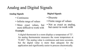
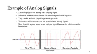
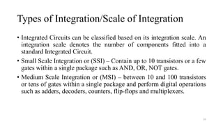
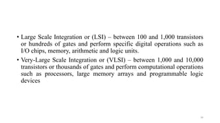
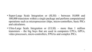
SlideShare a Scribd company logo
1 of 35
Introduction to Digital Logic
1
Analog and Digital Signals
Analog Signals
• Continuous
• Infinite range of values
• More exact values, but
more difficult to work with
Digital Signals
• Discrete
• Finite range of values
• Not as exact as analog,
but easier to work with
2
Example:
A digital thermostat in a room displays a temperature of 72.
An analog thermometer measures the room temperature at
72.482. The analog value is continuous and more accurate,
but the digital value is more than adequate for the
application and significantly easier to process electronically.
Example of Analog Signals
• An analog signal can be any time-varying signal.
• Minimum and maximum values can be either positive or negative.
• They can be periodic (repeating) or non-periodic.
• Sine waves and square waves are two common analog signals.
• Note that this square wave is not a digital signal because its minimum value
is negative.
3
0 volts
Sine Wave Square Wave
(not digital)
Random-Periodic
Parts of an Analog Signal
4
Amplitude
(peak-to-peak)
Amplitude
(peak)
Period
(T)
Hz
T
1
F 
Frequency:
Logic Levels
Before examining digital signals, we must define logic levels. A
logic level is a voltage level that represents a defined digital state.
Logic HIGH: The higher of two voltages, typically 5 volts
Logic LOW: The lower of two voltages, typically 0 volts
5
5.0 v
2.0 v
0.8 v
0.0 v Logic Low
Logic High
Invalid
Logic
Level
Logic Level Voltage True/False On/Off 0/1
HIGH 5 volts True On 1
LOW 0 volts False Off 0
Digital Signal
• A digital signal is a signal that is used to represent data as a sequence
of separate values at any point in time.
• It can only take on one of a fixed number of values.
• This type of signal represents a real number within a constant range of
values.
6
Example of Digital Signals
• Digital signal are commonly referred to as square waves or clock signals.
• Their minimum value must be 0 volts, and their maximum value must be 5
volts.
• They can be periodic (repeating) or non-periodic.
• The time the signal is high (tH) can vary anywhere from 1% of the period to
99% of the period.
7
0 volts
5 volts
Parts of a Digital Signal
8
Amplitude
Time
High
(tH)
Time
Low
(tL)
Period (T)
Rising Edge
Falling Edge
Amplitude:
For digital signals, this will ALWAYS be 5
volts.
Period:
The time it takes for a periodic signal to
repeat. (seconds)
Frequency:
A measure of the number of occurrences of
the signal per second. (Hertz, Hz)
Time High (tH):
The time the signal is at 5 v.
Time Low (tL):
The time the signal is at 0 v.
Duty Cycle:
The ratio of tH to the total period (T).
Rising Edge:
A 0-to-1 transition of the signal.
Falling Edge:
A 1-to-0 transition of the signal.
Hz
T
1
F 
Frequency:
%
100


T
t
DutyCycle H
Digital waveform
• Digital waveforms consist of voltage levels that are changing back and
forth between the HIGH and LOW levels or states.
• Figure 1–7(a) shows that a single positive-going pulse is generated
when the voltage (or current) goes from its normally LOW level to its
HIGH level and then back to its LOW level.
• The negative-going pulse in Figure 1–7(b) is generated when the
voltage goes from its normally HIGH level to its LOW level and back
to its HIGH level.
• A digital waveform is made up of a series of pulses.
11
Ideal Pulses
12
The Pulse
• As indicated in Figure 1–7, a pulse has two edges: a leading edge that
occurs first at time t0 and a trailing edge that occurs last at time t1.
• For a positive-going pulse, the leading edge is a rising edge, and the
trailing edge is a falling edge.
• The pulses in Figure 1–7 are ideal because the rising and falling edges
are assumed to change in zero time (instantaneously).
• In practice, these transitions never occur instantaneously, although for
most digital work you can assume ideal pulses.
13
Nonideal Pulse Characteristics
14
• Figure 1–8 shows a nonideal pulse. In reality, all pulses exhibit some
or all of these characteristics.
• The overshoot and ringing are sometimes produced by stray inductive
and capacitive effects.
• The droop can be caused by stray capacitive and circuit resistance,
forming an RC circuit with a low time constant.
• The time required for a pulse to go from its LOW level to its HIGH
level is called the rise time (tr), and the time required for the
transition from the HIGH level to the LOW level is called the fall time
(tf).
15
• In practice, it is common to measure rise time from 10% of the pulse
amplitude (height from baseline) to 90% of the pulse amplitude and to
measure the fall time from 90% to 10% of the pulse amplitude, as
indicated in Figure 1–8.
• The bottom 10% and the top 10% of the pulse are not included in the
rise and fall times because of the nonlinearities in the waveform in
these areas.
• The pulse width (tW) is a measure of the duration of the pulse and is
often defined as the time interval between the 50% points on the rising
and falling edges, as indicated in Figure 1–8.
16
Waveform Characteristics
• Most waveforms encountered in digital systems are composed of
series of pulses, sometimes called pulse trains, and can be classified as
either periodic or nonperiodic.
• A periodic pulse waveform is one that repeats itself at a fixed interval,
called a period (T).
• The frequency ( f ) is the rate at which it repeats itself and is
measured in hertz (Hz).
• A nonperiodic pulse waveform, of course, does not repeat itself at
fixed intervals and may be composed of pulses of randomly differing
pulse widths and/or randomly differing time intervals between the
pulses.
17
• An example of each type is shown in Figure 1–9.
18
• The frequency ( f ) of a pulse (digital) waveform is the reciprocal of
the period. The relationship between frequency and period is
expressed as follows:
• An important characteristic of a periodic digital waveform is its duty
cycle, which is the ratio of the pulse width (tW) to the period (T ). It
can be expressed as a percentage.
19
The Clock
• In digital systems, all waveforms are synchronized with a basic timing
waveform called the clock.
• The clock is a periodic waveform in which each interval between
pulses (the period) equals the time for one bit.
• An example of a clock waveform is shown in Figure 1–11.
• Notice that, in this case, each change in level of waveform A occurs at
the leading edge of the clock waveform.
• In other cases, level changes occur at the trailing edge of the clock.
20
• During each bit time of the clock, waveform A is either HIGH or
LOW.
• These HIGHs and LOWs represent a sequence of bits as indicated.
• A group of several bits can contain binary information, such as a
number or a letter.
• The clock waveform itself does not carry information.
21
22
Logic Gate
• It is an elementary building block of modern digital electronics.
• Most logic gates have two inputs and one output.
• At any given moment, every terminal is in one of the two binary
conditions, LOW or HIGH represented by different voltage level.
• A switch with an output that will only turn ON when inputs are in
particular position.
• Digital Logic is a representation of signals and a sequence of a digital
circuit through the numbers.
23
• It is the basis for digital computing and provides a fundamental
understanding on how circuits and hardware communicate within the
computer.
• Digital logic is typically embedded into most electronic devices like
mobile, computer, etc.
• Main components of digital logic consists of five different logic gates
i.e. AND, OR, NOT, NAND and NOR.
24
Digital Operations
• Arithmetic and Logic Operations
• Counter
• Multiplexer and Demultiplexer
• Encoder and Decoder
• etc…
25
Integrated Circuit(IC)
• Over the years we have observed how technology has managed to
squeeze itself to a more compact and concise structure.
• For instance, the first computers that were made were the size of a
warehouse of 1000 laptops which we use today.
• How has this been made possible?
• The integrated circuit is the answer to it.
• Three American scientists invented transistors which simplified things
to quite an extent, but it was the development of integrated circuits
that actually changed the face of the electronics technology.
26
• An integrated circuit (IC) is a miniature ,low cost electronic circuit
consisting of active and passive components fabricated together on a
single crystal of silicon.
• The active components are transistors and diodes and passive
components are resistors and capacitors.
• Digital system uses IC’s for many years because of their small size,
high reliability, low cost and low power consumption.
27
Advantages of integrated circuits
• 1. Miniaturization and hence increased equipment density.
• 2. Cost reduction due to batch processing.
• 3. Increased system reliability due to the elimination of soldered joints.
• 4. Improved functional performance.
• 5. Increased operating speeds.
• 6. Reduction in power consumption
28
• IC generally come in 2 types of packages i.e. flat type package and
dual inline package(DIP).
• DIP is most widely used type because of low price and easy to install
on circuit boards.
• The envelope of IC package is made up of plastics or ceramics.
• Most of package have standard size and number of pins range from 8-
64.
29
DIP
30
Flat Type
31
32
Types of Integration/Scale of Integration
• Integrated Circuits can be classified based on its integration scale. An
integration scale denotes the number of components fitted into a
standard Integrated Circuit.
• Small Scale Integration or (SSI) – Contain up to 10 transistors or a few
gates within a single package such as AND, OR, NOT gates.
• Medium Scale Integration or (MSI) – between 10 and 100 transistors
or tens of gates within a single package and perform digital operations
such as adders, decoders, counters, flip-flops and multiplexers.
33
• Large Scale Integration or (LSI) – between 100 and 1,000 transistors
or hundreds of gates and perform specific digital operations such as
I/O chips, memory, arithmetic and logic units.
• Very-Large Scale Integration or (VLSI) – between 1,000 and 10,000
transistors or thousands of gates and perform computational operations
such as processors, large memory arrays and programmable logic
devices
34
• Super-Large Scale Integration or (SLSI) – between 10,000 and
100,000 transistors within a single package and perform computational
operations such as microprocessor chips, micro-controllers, basic PICs
and calculators.
• Ultra-Large Scale Integration or (ULSI) – more than 1 million
transistors – the big boys that are used in computers CPUs, GPUs,
video processors, micro-controllers, FPGAs and complex PICs.
35
Assignment
• Study about Moore’s Law
• Study about IC Fabrication
• Write down the differences between Analog System & Digital System
36
End of Chapter One
Thank You
37

More Related Content

What's hot

INTERRUPTS OF 8086 MICROPROCESSOR
INTERRUPTS OF 8086 MICROPROCESSORINTERRUPTS OF 8086 MICROPROCESSOR
INTERRUPTS OF 8086 MICROPROCESSORGurudev joshi
 
encoder and decoder in digital electronics
encoder and decoder in digital electronicsencoder and decoder in digital electronics
encoder and decoder in digital electronicsvikram rajpurohit
 
Booth's algorithm part 2
Booth's algorithm part 2Booth's algorithm part 2
Booth's algorithm part 2babuece
 
multiplexer 4 input
multiplexer 4 inputmultiplexer 4 input
multiplexer 4 inputAnkit Mistry
 
Transistor Transistor Logic
Transistor Transistor LogicTransistor Transistor Logic
Transistor Transistor Logicsurat murthy
 
Sequential circuit design
Sequential circuit designSequential circuit design
Sequential circuit designSatya P. Joshi
 
transistor transistor logic
transistor transistor logictransistor transistor logic
transistor transistor logicmansi acharya
 
LPC 2148 ARM MICROCONTROLLER
LPC 2148 ARM MICROCONTROLLERLPC 2148 ARM MICROCONTROLLER
LPC 2148 ARM MICROCONTROLLERsravannunna24
 
Combinational circuits
Combinational circuits Combinational circuits
Combinational circuits DrSonali Vyas
 
Chapter 1 Introduction to Digital Logic
Chapter 1 Introduction to Digital LogicChapter 1 Introduction to Digital Logic
Chapter 1 Introduction to Digital LogicISMT College
 
Interrupt programming with 8051 microcontroller
Interrupt programming with 8051  microcontrollerInterrupt programming with 8051  microcontroller
Interrupt programming with 8051 microcontrollerAnkit Bhatnagar
 

What's hot (20)

INTERRUPTS OF 8086 MICROPROCESSOR
INTERRUPTS OF 8086 MICROPROCESSORINTERRUPTS OF 8086 MICROPROCESSOR
INTERRUPTS OF 8086 MICROPROCESSOR
 
flip flops
flip flops flip flops
flip flops
 
encoder and decoder in digital electronics
encoder and decoder in digital electronicsencoder and decoder in digital electronics
encoder and decoder in digital electronics
 
Booth's algorithm part 2
Booth's algorithm part 2Booth's algorithm part 2
Booth's algorithm part 2
 
Adc interfacing
Adc interfacingAdc interfacing
Adc interfacing
 
multiplexer 4 input
multiplexer 4 inputmultiplexer 4 input
multiplexer 4 input
 
Data encoding
Data encodingData encoding
Data encoding
 
Transistor Transistor Logic
Transistor Transistor LogicTransistor Transistor Logic
Transistor Transistor Logic
 
Sequential circuit design
Sequential circuit designSequential circuit design
Sequential circuit design
 
transistor transistor logic
transistor transistor logictransistor transistor logic
transistor transistor logic
 
Chapter 5 counter
Chapter 5 counterChapter 5 counter
Chapter 5 counter
 
LPC 2148 ARM MICROCONTROLLER
LPC 2148 ARM MICROCONTROLLERLPC 2148 ARM MICROCONTROLLER
LPC 2148 ARM MICROCONTROLLER
 
Bcd
BcdBcd
Bcd
 
Encoder
EncoderEncoder
Encoder
 
Combinational circuit
Combinational circuitCombinational circuit
Combinational circuit
 
Combinational circuits
Combinational circuits Combinational circuits
Combinational circuits
 
Digital Logic Design
Digital Logic Design Digital Logic Design
Digital Logic Design
 
Chapter 1 Introduction to Digital Logic
Chapter 1 Introduction to Digital LogicChapter 1 Introduction to Digital Logic
Chapter 1 Introduction to Digital Logic
 
8051 interrupts
8051 interrupts8051 interrupts
8051 interrupts
 
Interrupt programming with 8051 microcontroller
Interrupt programming with 8051  microcontrollerInterrupt programming with 8051  microcontroller
Interrupt programming with 8051 microcontroller
 

Similar to Chapter 1 Introduction to Digital Logic

Analog and Digital Signals presenation.ppt
Analog and Digital Signals presenation.pptAnalog and Digital Signals presenation.ppt
Analog and Digital Signals presenation.pptAbdulWahabAslam3
 
AnalogDigitalSignals1.ppt signal inputs outputs
AnalogDigitalSignals1.ppt signal inputs outputsAnalogDigitalSignals1.ppt signal inputs outputs
AnalogDigitalSignals1.ppt signal inputs outputsMuhammedNazer
 
Chapter 1_Introduction to digital design (EEEg4302).pdf
Chapter 1_Introduction to digital design (EEEg4302).pdfChapter 1_Introduction to digital design (EEEg4302).pdf
Chapter 1_Introduction to digital design (EEEg4302).pdfTamiratDejene1
 
IS 151 lecture 2
IS 151   lecture 2IS 151   lecture 2
IS 151 lecture 2wajanga
 
IS 151 Lecture 2
IS 151 Lecture 2IS 151 Lecture 2
IS 151 Lecture 2wajanga
 
Introduction to communication system.pdf
Introduction to communication system.pdfIntroduction to communication system.pdf
Introduction to communication system.pdfChristineTorrepenida1
 
Te442 lecture02-2016-14-4-2016-1
Te442 lecture02-2016-14-4-2016-1Te442 lecture02-2016-14-4-2016-1
Te442 lecture02-2016-14-4-2016-1colman mboya
 
TYPES OF SIGNAL.pptx
TYPES OF SIGNAL.pptxTYPES OF SIGNAL.pptx
TYPES OF SIGNAL.pptxsaiscount01
 
OSI Model - Analog and digital signal conversion and processing
OSI Model - Analog and digital signal conversion and processingOSI Model - Analog and digital signal conversion and processing
OSI Model - Analog and digital signal conversion and processingRolando Ramos III
 
Noise influence and environmental impact
Noise influence and environmental impactNoise influence and environmental impact
Noise influence and environmental impactchilinks4all1
 
Introduction to Analog signal
Introduction to Analog signalIntroduction to Analog signal
Introduction to Analog signalHirdesh Vishwdewa
 
Telecom lect 6
Telecom lect 6Telecom lect 6
Telecom lect 6Shiraz316
 
Signal encoding techniques
Signal encoding techniquesSignal encoding techniques
Signal encoding techniquesSyed Zaid Irshad
 
DIGITAL-ELECTRONICS-DESIGN.pptx
DIGITAL-ELECTRONICS-DESIGN.pptxDIGITAL-ELECTRONICS-DESIGN.pptx
DIGITAL-ELECTRONICS-DESIGN.pptxSofiaArquero2
 
Data acquisition and conversion
Data acquisition and conversionData acquisition and conversion
Data acquisition and conversionTejas Prajapati
 
Analog digitalsignals
Analog digitalsignalsAnalog digitalsignals
Analog digitalsignalsrofldork
 

Similar to Chapter 1 Introduction to Digital Logic (20)

AnalogDigitalSignals1.ppt
AnalogDigitalSignals1.pptAnalogDigitalSignals1.ppt
AnalogDigitalSignals1.ppt
 
Analog and Digital Signals presenation.ppt
Analog and Digital Signals presenation.pptAnalog and Digital Signals presenation.ppt
Analog and Digital Signals presenation.ppt
 
AnalogDigitalSignals1.ppt signal inputs outputs
AnalogDigitalSignals1.ppt signal inputs outputsAnalogDigitalSignals1.ppt signal inputs outputs
AnalogDigitalSignals1.ppt signal inputs outputs
 
Chapter 1_Introduction to digital design (EEEg4302).pdf
Chapter 1_Introduction to digital design (EEEg4302).pdfChapter 1_Introduction to digital design (EEEg4302).pdf
Chapter 1_Introduction to digital design (EEEg4302).pdf
 
IS 151 lecture 2
IS 151   lecture 2IS 151   lecture 2
IS 151 lecture 2
 
Chapter 1.pptx
Chapter 1.pptxChapter 1.pptx
Chapter 1.pptx
 
IS 151 Lecture 2
IS 151 Lecture 2IS 151 Lecture 2
IS 151 Lecture 2
 
S&s lec1
S&s lec1S&s lec1
S&s lec1
 
Introduction to communication system.pdf
Introduction to communication system.pdfIntroduction to communication system.pdf
Introduction to communication system.pdf
 
Te442 lecture02-2016-14-4-2016-1
Te442 lecture02-2016-14-4-2016-1Te442 lecture02-2016-14-4-2016-1
Te442 lecture02-2016-14-4-2016-1
 
TYPES OF SIGNAL.pptx
TYPES OF SIGNAL.pptxTYPES OF SIGNAL.pptx
TYPES OF SIGNAL.pptx
 
OSI Model - Analog and digital signal conversion and processing
OSI Model - Analog and digital signal conversion and processingOSI Model - Analog and digital signal conversion and processing
OSI Model - Analog and digital signal conversion and processing
 
Computer hardware
Computer hardware Computer hardware
Computer hardware
 
Noise influence and environmental impact
Noise influence and environmental impactNoise influence and environmental impact
Noise influence and environmental impact
 
Introduction to Analog signal
Introduction to Analog signalIntroduction to Analog signal
Introduction to Analog signal
 
Telecom lect 6
Telecom lect 6Telecom lect 6
Telecom lect 6
 
Signal encoding techniques
Signal encoding techniquesSignal encoding techniques
Signal encoding techniques
 
DIGITAL-ELECTRONICS-DESIGN.pptx
DIGITAL-ELECTRONICS-DESIGN.pptxDIGITAL-ELECTRONICS-DESIGN.pptx
DIGITAL-ELECTRONICS-DESIGN.pptx
 
Data acquisition and conversion
Data acquisition and conversionData acquisition and conversion
Data acquisition and conversion
 
Analog digitalsignals
Analog digitalsignalsAnalog digitalsignals
Analog digitalsignals
 

More from ISMT College

Time delays & counter.ppt
Time delays & counter.pptTime delays & counter.ppt
Time delays & counter.pptISMT College
 
Timing Diagram.pptx
Timing Diagram.pptxTiming Diagram.pptx
Timing Diagram.pptxISMT College
 
4. Instruction Set Of MP 8085.pptx
4. Instruction Set Of MP 8085.pptx4. Instruction Set Of MP 8085.pptx
4. Instruction Set Of MP 8085.pptxISMT College
 
3. Addressing Modes in 8085 microprocessor.pptx
3. Addressing Modes in 8085 microprocessor.pptx3. Addressing Modes in 8085 microprocessor.pptx
3. Addressing Modes in 8085 microprocessor.pptxISMT College
 
2. 8085-Microprocessor.pptx
2. 8085-Microprocessor.pptx2. 8085-Microprocessor.pptx
2. 8085-Microprocessor.pptxISMT College
 
1. Introduction to Microprocessor.pptx
1. Introduction to Microprocessor.pptx1. Introduction to Microprocessor.pptx
1. Introduction to Microprocessor.pptxISMT College
 
Digital Logic BCA TU Chapter 2.2
Digital Logic BCA TU Chapter 2.2Digital Logic BCA TU Chapter 2.2
Digital Logic BCA TU Chapter 2.2ISMT College
 
Access Control List (ACL)
Access Control List (ACL)Access Control List (ACL)
Access Control List (ACL)ISMT College
 
Introduction to Counters
Introduction to CountersIntroduction to Counters
Introduction to CountersISMT College
 
Chapter 2.1 introduction to number system
Chapter 2.1 introduction to number systemChapter 2.1 introduction to number system
Chapter 2.1 introduction to number systemISMT College
 
Programmable logic devices
Programmable logic devicesProgrammable logic devices
Programmable logic devicesISMT College
 
Basic Gates in Digital Logic
Basic Gates in Digital LogicBasic Gates in Digital Logic
Basic Gates in Digital LogicISMT College
 
Adder & subtractor (Half adder, Full adder, Half subtractor, Full subtractor)
Adder & subtractor (Half adder, Full adder, Half subtractor, Full subtractor)Adder & subtractor (Half adder, Full adder, Half subtractor, Full subtractor)
Adder & subtractor (Half adder, Full adder, Half subtractor, Full subtractor)ISMT College
 
Register in Digital Logic
Register in Digital LogicRegister in Digital Logic
Register in Digital LogicISMT College
 

More from ISMT College (17)

Attack.pptx
Attack.pptxAttack.pptx
Attack.pptx
 
Time delays & counter.ppt
Time delays & counter.pptTime delays & counter.ppt
Time delays & counter.ppt
 
Timing Diagram.pptx
Timing Diagram.pptxTiming Diagram.pptx
Timing Diagram.pptx
 
4. Instruction Set Of MP 8085.pptx
4. Instruction Set Of MP 8085.pptx4. Instruction Set Of MP 8085.pptx
4. Instruction Set Of MP 8085.pptx
 
Instruction.pdf
Instruction.pdfInstruction.pdf
Instruction.pdf
 
3. Addressing Modes in 8085 microprocessor.pptx
3. Addressing Modes in 8085 microprocessor.pptx3. Addressing Modes in 8085 microprocessor.pptx
3. Addressing Modes in 8085 microprocessor.pptx
 
2. 8085-Microprocessor.pptx
2. 8085-Microprocessor.pptx2. 8085-Microprocessor.pptx
2. 8085-Microprocessor.pptx
 
1. Introduction to Microprocessor.pptx
1. Introduction to Microprocessor.pptx1. Introduction to Microprocessor.pptx
1. Introduction to Microprocessor.pptx
 
Digital Logic BCA TU Chapter 2.2
Digital Logic BCA TU Chapter 2.2Digital Logic BCA TU Chapter 2.2
Digital Logic BCA TU Chapter 2.2
 
VLAN
VLANVLAN
VLAN
 
Access Control List (ACL)
Access Control List (ACL)Access Control List (ACL)
Access Control List (ACL)
 
Introduction to Counters
Introduction to CountersIntroduction to Counters
Introduction to Counters
 
Chapter 2.1 introduction to number system
Chapter 2.1 introduction to number systemChapter 2.1 introduction to number system
Chapter 2.1 introduction to number system
 
Programmable logic devices
Programmable logic devicesProgrammable logic devices
Programmable logic devices
 
Basic Gates in Digital Logic
Basic Gates in Digital LogicBasic Gates in Digital Logic
Basic Gates in Digital Logic
 
Adder & subtractor (Half adder, Full adder, Half subtractor, Full subtractor)
Adder & subtractor (Half adder, Full adder, Half subtractor, Full subtractor)Adder & subtractor (Half adder, Full adder, Half subtractor, Full subtractor)
Adder & subtractor (Half adder, Full adder, Half subtractor, Full subtractor)
 
Register in Digital Logic
Register in Digital LogicRegister in Digital Logic
Register in Digital Logic
 

Recently uploaded

The Most Attractive Pune Call Girls Budhwar Peth 8250192130 Will You Miss Thi...
The Most Attractive Pune Call Girls Budhwar Peth 8250192130 Will You Miss Thi...The Most Attractive Pune Call Girls Budhwar Peth 8250192130 Will You Miss Thi...
The Most Attractive Pune Call Girls Budhwar Peth 8250192130 Will You Miss Thi...ranjana rawat
 
VIP Call Girls Service Kondapur Hyderabad Call +91-8250192130
VIP Call Girls Service Kondapur Hyderabad Call +91-8250192130VIP Call Girls Service Kondapur Hyderabad Call +91-8250192130
VIP Call Girls Service Kondapur Hyderabad Call +91-8250192130Suhani Kapoor
 
HARMONY IN THE NATURE AND EXISTENCE - Unit-IV
HARMONY IN THE NATURE AND EXISTENCE - Unit-IVHARMONY IN THE NATURE AND EXISTENCE - Unit-IV
HARMONY IN THE NATURE AND EXISTENCE - Unit-IVRajaP95
 
MANUFACTURING PROCESS-II UNIT-2 LATHE MACHINE
MANUFACTURING PROCESS-II UNIT-2 LATHE MACHINEMANUFACTURING PROCESS-II UNIT-2 LATHE MACHINE
MANUFACTURING PROCESS-II UNIT-2 LATHE MACHINESIVASHANKAR N
 
(RIA) Call Girls Bhosari ( 7001035870 ) HI-Fi Pune Escorts Service
(RIA) Call Girls Bhosari ( 7001035870 ) HI-Fi Pune Escorts Service(RIA) Call Girls Bhosari ( 7001035870 ) HI-Fi Pune Escorts Service
(RIA) Call Girls Bhosari ( 7001035870 ) HI-Fi Pune Escorts Serviceranjana rawat
 
Analog to Digital and Digital to Analog Converter
Analog to Digital and Digital to Analog ConverterAnalog to Digital and Digital to Analog Converter
Analog to Digital and Digital to Analog ConverterAbhinavSharma374939
 
Microscopic Analysis of Ceramic Materials.pptx
Microscopic Analysis of Ceramic Materials.pptxMicroscopic Analysis of Ceramic Materials.pptx
Microscopic Analysis of Ceramic Materials.pptxpurnimasatapathy1234
 
(ANJALI) Dange Chowk Call Girls Just Call 7001035870 [ Cash on Delivery ] Pun...
(ANJALI) Dange Chowk Call Girls Just Call 7001035870 [ Cash on Delivery ] Pun...(ANJALI) Dange Chowk Call Girls Just Call 7001035870 [ Cash on Delivery ] Pun...
(ANJALI) Dange Chowk Call Girls Just Call 7001035870 [ Cash on Delivery ] Pun...ranjana rawat
 
APPLICATIONS-AC/DC DRIVES-OPERATING CHARACTERISTICS
APPLICATIONS-AC/DC DRIVES-OPERATING CHARACTERISTICSAPPLICATIONS-AC/DC DRIVES-OPERATING CHARACTERISTICS
APPLICATIONS-AC/DC DRIVES-OPERATING CHARACTERISTICSKurinjimalarL3
 
Processing & Properties of Floor and Wall Tiles.pptx
Processing & Properties of Floor and Wall Tiles.pptxProcessing & Properties of Floor and Wall Tiles.pptx
Processing & Properties of Floor and Wall Tiles.pptxpranjaldaimarysona
 
HARDNESS, FRACTURE TOUGHNESS AND STRENGTH OF CERAMICS
HARDNESS, FRACTURE TOUGHNESS AND STRENGTH OF CERAMICSHARDNESS, FRACTURE TOUGHNESS AND STRENGTH OF CERAMICS
HARDNESS, FRACTURE TOUGHNESS AND STRENGTH OF CERAMICSRajkumarAkumalla
 
(SHREYA) Chakan Call Girls Just Call 7001035870 [ Cash on Delivery ] Pune Esc...
(SHREYA) Chakan Call Girls Just Call 7001035870 [ Cash on Delivery ] Pune Esc...(SHREYA) Chakan Call Girls Just Call 7001035870 [ Cash on Delivery ] Pune Esc...
(SHREYA) Chakan Call Girls Just Call 7001035870 [ Cash on Delivery ] Pune Esc...ranjana rawat
 
main PPT.pptx of girls hostel security using rfid
main PPT.pptx of girls hostel security using rfidmain PPT.pptx of girls hostel security using rfid
main PPT.pptx of girls hostel security using rfidNikhilNagaraju
 
Introduction to Multiple Access Protocol.pptx
Introduction to Multiple Access Protocol.pptxIntroduction to Multiple Access Protocol.pptx
Introduction to Multiple Access Protocol.pptxupamatechverse
 
Architect Hassan Khalil Portfolio for 2024
Architect Hassan Khalil Portfolio for 2024Architect Hassan Khalil Portfolio for 2024
Architect Hassan Khalil Portfolio for 2024hassan khalil
 
(ANVI) Koregaon Park Call Girls Just Call 7001035870 [ Cash on Delivery ] Pun...
(ANVI) Koregaon Park Call Girls Just Call 7001035870 [ Cash on Delivery ] Pun...(ANVI) Koregaon Park Call Girls Just Call 7001035870 [ Cash on Delivery ] Pun...
(ANVI) Koregaon Park Call Girls Just Call 7001035870 [ Cash on Delivery ] Pun...ranjana rawat
 

Recently uploaded (20)

The Most Attractive Pune Call Girls Budhwar Peth 8250192130 Will You Miss Thi...
The Most Attractive Pune Call Girls Budhwar Peth 8250192130 Will You Miss Thi...The Most Attractive Pune Call Girls Budhwar Peth 8250192130 Will You Miss Thi...
The Most Attractive Pune Call Girls Budhwar Peth 8250192130 Will You Miss Thi...
 
VIP Call Girls Service Kondapur Hyderabad Call +91-8250192130
VIP Call Girls Service Kondapur Hyderabad Call +91-8250192130VIP Call Girls Service Kondapur Hyderabad Call +91-8250192130
VIP Call Girls Service Kondapur Hyderabad Call +91-8250192130
 
HARMONY IN THE NATURE AND EXISTENCE - Unit-IV
HARMONY IN THE NATURE AND EXISTENCE - Unit-IVHARMONY IN THE NATURE AND EXISTENCE - Unit-IV
HARMONY IN THE NATURE AND EXISTENCE - Unit-IV
 
MANUFACTURING PROCESS-II UNIT-2 LATHE MACHINE
MANUFACTURING PROCESS-II UNIT-2 LATHE MACHINEMANUFACTURING PROCESS-II UNIT-2 LATHE MACHINE
MANUFACTURING PROCESS-II UNIT-2 LATHE MACHINE
 
(RIA) Call Girls Bhosari ( 7001035870 ) HI-Fi Pune Escorts Service
(RIA) Call Girls Bhosari ( 7001035870 ) HI-Fi Pune Escorts Service(RIA) Call Girls Bhosari ( 7001035870 ) HI-Fi Pune Escorts Service
(RIA) Call Girls Bhosari ( 7001035870 ) HI-Fi Pune Escorts Service
 
Call Us -/9953056974- Call Girls In Vikaspuri-/- Delhi NCR
Call Us -/9953056974- Call Girls In Vikaspuri-/- Delhi NCRCall Us -/9953056974- Call Girls In Vikaspuri-/- Delhi NCR
Call Us -/9953056974- Call Girls In Vikaspuri-/- Delhi NCR
 
Analog to Digital and Digital to Analog Converter
Analog to Digital and Digital to Analog ConverterAnalog to Digital and Digital to Analog Converter
Analog to Digital and Digital to Analog Converter
 
Microscopic Analysis of Ceramic Materials.pptx
Microscopic Analysis of Ceramic Materials.pptxMicroscopic Analysis of Ceramic Materials.pptx
Microscopic Analysis of Ceramic Materials.pptx
 
Roadmap to Membership of RICS - Pathways and Routes
Roadmap to Membership of RICS - Pathways and RoutesRoadmap to Membership of RICS - Pathways and Routes
Roadmap to Membership of RICS - Pathways and Routes
 
Exploring_Network_Security_with_JA3_by_Rakesh Seal.pptx
Exploring_Network_Security_with_JA3_by_Rakesh Seal.pptxExploring_Network_Security_with_JA3_by_Rakesh Seal.pptx
Exploring_Network_Security_with_JA3_by_Rakesh Seal.pptx
 
DJARUM4D - SLOT GACOR ONLINE | SLOT DEMO ONLINE
DJARUM4D - SLOT GACOR ONLINE | SLOT DEMO ONLINEDJARUM4D - SLOT GACOR ONLINE | SLOT DEMO ONLINE
DJARUM4D - SLOT GACOR ONLINE | SLOT DEMO ONLINE
 
(ANJALI) Dange Chowk Call Girls Just Call 7001035870 [ Cash on Delivery ] Pun...
(ANJALI) Dange Chowk Call Girls Just Call 7001035870 [ Cash on Delivery ] Pun...(ANJALI) Dange Chowk Call Girls Just Call 7001035870 [ Cash on Delivery ] Pun...
(ANJALI) Dange Chowk Call Girls Just Call 7001035870 [ Cash on Delivery ] Pun...
 
APPLICATIONS-AC/DC DRIVES-OPERATING CHARACTERISTICS
APPLICATIONS-AC/DC DRIVES-OPERATING CHARACTERISTICSAPPLICATIONS-AC/DC DRIVES-OPERATING CHARACTERISTICS
APPLICATIONS-AC/DC DRIVES-OPERATING CHARACTERISTICS
 
Processing & Properties of Floor and Wall Tiles.pptx
Processing & Properties of Floor and Wall Tiles.pptxProcessing & Properties of Floor and Wall Tiles.pptx
Processing & Properties of Floor and Wall Tiles.pptx
 
HARDNESS, FRACTURE TOUGHNESS AND STRENGTH OF CERAMICS
HARDNESS, FRACTURE TOUGHNESS AND STRENGTH OF CERAMICSHARDNESS, FRACTURE TOUGHNESS AND STRENGTH OF CERAMICS
HARDNESS, FRACTURE TOUGHNESS AND STRENGTH OF CERAMICS
 
(SHREYA) Chakan Call Girls Just Call 7001035870 [ Cash on Delivery ] Pune Esc...
(SHREYA) Chakan Call Girls Just Call 7001035870 [ Cash on Delivery ] Pune Esc...(SHREYA) Chakan Call Girls Just Call 7001035870 [ Cash on Delivery ] Pune Esc...
(SHREYA) Chakan Call Girls Just Call 7001035870 [ Cash on Delivery ] Pune Esc...
 
main PPT.pptx of girls hostel security using rfid
main PPT.pptx of girls hostel security using rfidmain PPT.pptx of girls hostel security using rfid
main PPT.pptx of girls hostel security using rfid
 
Introduction to Multiple Access Protocol.pptx
Introduction to Multiple Access Protocol.pptxIntroduction to Multiple Access Protocol.pptx
Introduction to Multiple Access Protocol.pptx
 
Architect Hassan Khalil Portfolio for 2024
Architect Hassan Khalil Portfolio for 2024Architect Hassan Khalil Portfolio for 2024
Architect Hassan Khalil Portfolio for 2024
 
(ANVI) Koregaon Park Call Girls Just Call 7001035870 [ Cash on Delivery ] Pun...
(ANVI) Koregaon Park Call Girls Just Call 7001035870 [ Cash on Delivery ] Pun...(ANVI) Koregaon Park Call Girls Just Call 7001035870 [ Cash on Delivery ] Pun...
(ANVI) Koregaon Park Call Girls Just Call 7001035870 [ Cash on Delivery ] Pun...
 

Chapter 1 Introduction to Digital Logic

  • 2. Analog and Digital Signals Analog Signals • Continuous • Infinite range of values • More exact values, but more difficult to work with Digital Signals • Discrete • Finite range of values • Not as exact as analog, but easier to work with 2 Example: A digital thermostat in a room displays a temperature of 72. An analog thermometer measures the room temperature at 72.482. The analog value is continuous and more accurate, but the digital value is more than adequate for the application and significantly easier to process electronically.
  • 3. Example of Analog Signals • An analog signal can be any time-varying signal. • Minimum and maximum values can be either positive or negative. • They can be periodic (repeating) or non-periodic. • Sine waves and square waves are two common analog signals. • Note that this square wave is not a digital signal because its minimum value is negative. 3 0 volts Sine Wave Square Wave (not digital) Random-Periodic
  • 4. Parts of an Analog Signal 4 Amplitude (peak-to-peak) Amplitude (peak) Period (T) Hz T 1 F  Frequency:
  • 5. Logic Levels Before examining digital signals, we must define logic levels. A logic level is a voltage level that represents a defined digital state. Logic HIGH: The higher of two voltages, typically 5 volts Logic LOW: The lower of two voltages, typically 0 volts 5 5.0 v 2.0 v 0.8 v 0.0 v Logic Low Logic High Invalid Logic Level Logic Level Voltage True/False On/Off 0/1 HIGH 5 volts True On 1 LOW 0 volts False Off 0
  • 6. Digital Signal • A digital signal is a signal that is used to represent data as a sequence of separate values at any point in time. • It can only take on one of a fixed number of values. • This type of signal represents a real number within a constant range of values. 6
  • 7. Example of Digital Signals • Digital signal are commonly referred to as square waves or clock signals. • Their minimum value must be 0 volts, and their maximum value must be 5 volts. • They can be periodic (repeating) or non-periodic. • The time the signal is high (tH) can vary anywhere from 1% of the period to 99% of the period. 7 0 volts 5 volts
  • 8. Parts of a Digital Signal 8 Amplitude Time High (tH) Time Low (tL) Period (T) Rising Edge Falling Edge Amplitude: For digital signals, this will ALWAYS be 5 volts. Period: The time it takes for a periodic signal to repeat. (seconds) Frequency: A measure of the number of occurrences of the signal per second. (Hertz, Hz) Time High (tH): The time the signal is at 5 v. Time Low (tL): The time the signal is at 0 v. Duty Cycle: The ratio of tH to the total period (T). Rising Edge: A 0-to-1 transition of the signal. Falling Edge: A 1-to-0 transition of the signal. Hz T 1 F  Frequency: % 100   T t DutyCycle H
  • 9. Digital waveform • Digital waveforms consist of voltage levels that are changing back and forth between the HIGH and LOW levels or states. • Figure 1–7(a) shows that a single positive-going pulse is generated when the voltage (or current) goes from its normally LOW level to its HIGH level and then back to its LOW level. • The negative-going pulse in Figure 1–7(b) is generated when the voltage goes from its normally HIGH level to its LOW level and back to its HIGH level. • A digital waveform is made up of a series of pulses. 11
  • 11. The Pulse • As indicated in Figure 1–7, a pulse has two edges: a leading edge that occurs first at time t0 and a trailing edge that occurs last at time t1. • For a positive-going pulse, the leading edge is a rising edge, and the trailing edge is a falling edge. • The pulses in Figure 1–7 are ideal because the rising and falling edges are assumed to change in zero time (instantaneously). • In practice, these transitions never occur instantaneously, although for most digital work you can assume ideal pulses. 13
  • 13. • Figure 1–8 shows a nonideal pulse. In reality, all pulses exhibit some or all of these characteristics. • The overshoot and ringing are sometimes produced by stray inductive and capacitive effects. • The droop can be caused by stray capacitive and circuit resistance, forming an RC circuit with a low time constant. • The time required for a pulse to go from its LOW level to its HIGH level is called the rise time (tr), and the time required for the transition from the HIGH level to the LOW level is called the fall time (tf). 15
  • 14. • In practice, it is common to measure rise time from 10% of the pulse amplitude (height from baseline) to 90% of the pulse amplitude and to measure the fall time from 90% to 10% of the pulse amplitude, as indicated in Figure 1–8. • The bottom 10% and the top 10% of the pulse are not included in the rise and fall times because of the nonlinearities in the waveform in these areas. • The pulse width (tW) is a measure of the duration of the pulse and is often defined as the time interval between the 50% points on the rising and falling edges, as indicated in Figure 1–8. 16
  • 15. Waveform Characteristics • Most waveforms encountered in digital systems are composed of series of pulses, sometimes called pulse trains, and can be classified as either periodic or nonperiodic. • A periodic pulse waveform is one that repeats itself at a fixed interval, called a period (T). • The frequency ( f ) is the rate at which it repeats itself and is measured in hertz (Hz). • A nonperiodic pulse waveform, of course, does not repeat itself at fixed intervals and may be composed of pulses of randomly differing pulse widths and/or randomly differing time intervals between the pulses. 17
  • 16. • An example of each type is shown in Figure 1–9. 18
  • 17. • The frequency ( f ) of a pulse (digital) waveform is the reciprocal of the period. The relationship between frequency and period is expressed as follows: • An important characteristic of a periodic digital waveform is its duty cycle, which is the ratio of the pulse width (tW) to the period (T ). It can be expressed as a percentage. 19
  • 18. The Clock • In digital systems, all waveforms are synchronized with a basic timing waveform called the clock. • The clock is a periodic waveform in which each interval between pulses (the period) equals the time for one bit. • An example of a clock waveform is shown in Figure 1–11. • Notice that, in this case, each change in level of waveform A occurs at the leading edge of the clock waveform. • In other cases, level changes occur at the trailing edge of the clock. 20
  • 19. • During each bit time of the clock, waveform A is either HIGH or LOW. • These HIGHs and LOWs represent a sequence of bits as indicated. • A group of several bits can contain binary information, such as a number or a letter. • The clock waveform itself does not carry information. 21
  • 20. 22
  • 21. Logic Gate • It is an elementary building block of modern digital electronics. • Most logic gates have two inputs and one output. • At any given moment, every terminal is in one of the two binary conditions, LOW or HIGH represented by different voltage level. • A switch with an output that will only turn ON when inputs are in particular position. • Digital Logic is a representation of signals and a sequence of a digital circuit through the numbers. 23
  • 22. • It is the basis for digital computing and provides a fundamental understanding on how circuits and hardware communicate within the computer. • Digital logic is typically embedded into most electronic devices like mobile, computer, etc. • Main components of digital logic consists of five different logic gates i.e. AND, OR, NOT, NAND and NOR. 24
  • 23. Digital Operations • Arithmetic and Logic Operations • Counter • Multiplexer and Demultiplexer • Encoder and Decoder • etc… 25
  • 24. Integrated Circuit(IC) • Over the years we have observed how technology has managed to squeeze itself to a more compact and concise structure. • For instance, the first computers that were made were the size of a warehouse of 1000 laptops which we use today. • How has this been made possible? • The integrated circuit is the answer to it. • Three American scientists invented transistors which simplified things to quite an extent, but it was the development of integrated circuits that actually changed the face of the electronics technology. 26
  • 25. • An integrated circuit (IC) is a miniature ,low cost electronic circuit consisting of active and passive components fabricated together on a single crystal of silicon. • The active components are transistors and diodes and passive components are resistors and capacitors. • Digital system uses IC’s for many years because of their small size, high reliability, low cost and low power consumption. 27
  • 26. Advantages of integrated circuits • 1. Miniaturization and hence increased equipment density. • 2. Cost reduction due to batch processing. • 3. Increased system reliability due to the elimination of soldered joints. • 4. Improved functional performance. • 5. Increased operating speeds. • 6. Reduction in power consumption 28
  • 27. • IC generally come in 2 types of packages i.e. flat type package and dual inline package(DIP). • DIP is most widely used type because of low price and easy to install on circuit boards. • The envelope of IC package is made up of plastics or ceramics. • Most of package have standard size and number of pins range from 8- 64. 29
  • 30. 32
  • 31. Types of Integration/Scale of Integration • Integrated Circuits can be classified based on its integration scale. An integration scale denotes the number of components fitted into a standard Integrated Circuit. • Small Scale Integration or (SSI) – Contain up to 10 transistors or a few gates within a single package such as AND, OR, NOT gates. • Medium Scale Integration or (MSI) – between 10 and 100 transistors or tens of gates within a single package and perform digital operations such as adders, decoders, counters, flip-flops and multiplexers. 33
  • 32. • Large Scale Integration or (LSI) – between 100 and 1,000 transistors or hundreds of gates and perform specific digital operations such as I/O chips, memory, arithmetic and logic units. • Very-Large Scale Integration or (VLSI) – between 1,000 and 10,000 transistors or thousands of gates and perform computational operations such as processors, large memory arrays and programmable logic devices 34
  • 33. • Super-Large Scale Integration or (SLSI) – between 10,000 and 100,000 transistors within a single package and perform computational operations such as microprocessor chips, micro-controllers, basic PICs and calculators. • Ultra-Large Scale Integration or (ULSI) – more than 1 million transistors – the big boys that are used in computers CPUs, GPUs, video processors, micro-controllers, FPGAs and complex PICs. 35
  • 34. Assignment • Study about Moore’s Law • Study about IC Fabrication • Write down the differences between Analog System & Digital System 36
  • 35. End of Chapter One Thank You 37

Editor's Notes

  1. This slide defines analog and digital signals and gives several examples of each.
  2. Examples of common analog signals.
  3. Parts of an analog signal: amplitude, period, & frequency.
  4. This slide introduces the concept of logic levels, gives the range of acceptable voltages for a logic high & low, and lists other common terms used to describe logic levels.
  5. Examples of common digital signals.
  6. The parts of a digital signal: amplitude, period & frequency, time high, time low, duty cycle, rising & falling edge.