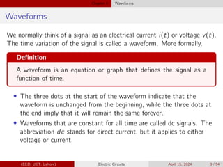
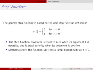
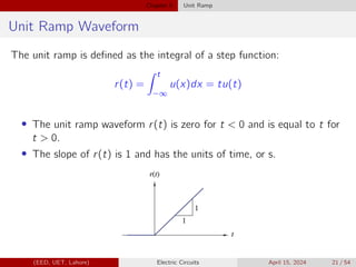
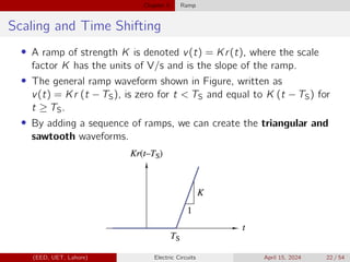
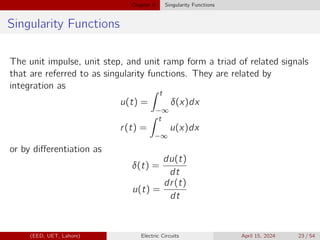
Chapter 5 of the EE-100 lecture on electric circuits focuses on different waveforms, including step, impulse, ramp, and exponential waveforms, defining a waveform as an electrical signal's time variation. It covers concepts like DC signals, unit step functions, and their mathematical representations, along with properties such as scaling and time shifting. The chapter also highlights the relationship between singularity functions and integration and differentiation in signal analysis.

![Chapter 5 Rectangular Function
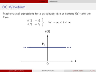
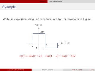
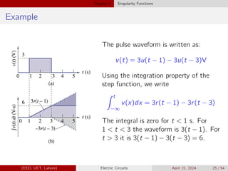
Waveforms - Example - Rectangular Function
v(t) = 3u(t − 1) − 3u(t − 3)V
A generalized rectangular
function is given as:
v(t) = VA [u (t − T1) − u (t − T2)]
(EED, UET, Lahore) Electric Circuits April 15, 2024 13 / 54](https://image.slidesharecdn.com/ee100chapter5waveforms-240814093650-81ddea28/85/Waveforms-EE_100_Chapter_5___Waveforms-pdf-13-320.jpg)
![Chapter 5 Singularity Functions
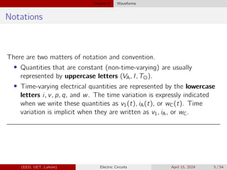
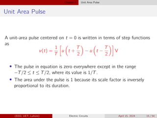
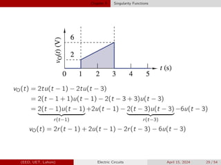
vO(t) =
0 t 1
2t 1 t 3
0 3 t
In terms of gate function:
vO(t) = 2t[u(t − 1) − u(t − 3)]
| {z }
Gate function
(EED, UET, Lahore) Electric Circuits April 15, 2024 28 / 54](https://image.slidesharecdn.com/ee100chapter5waveforms-240814093650-81ddea28/85/Waveforms-EE_100_Chapter_5___Waveforms-pdf-28-320.jpg)
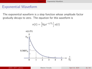
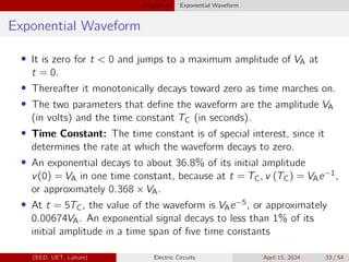
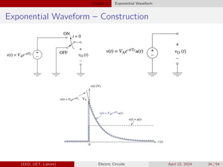
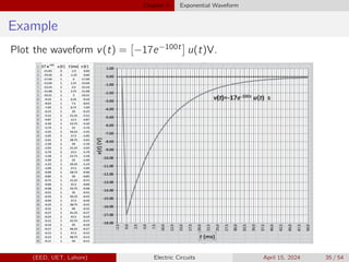
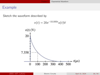
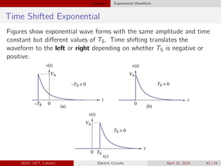
![Chapter 5 Exponential Waveform
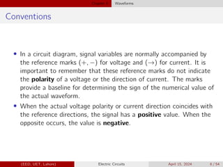
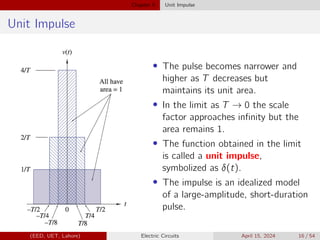
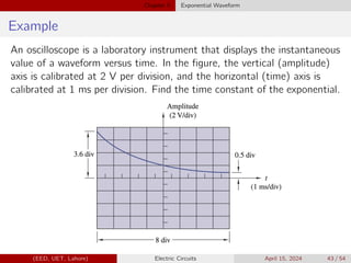
Example
Figure shows three exponential waveforms. Match each curve with the
appropriate expression.
1 v1(t) = 100e−(t/100µ)u(t − 100µ) V
2 v2(t) = 100e−(t/100µ)u(t) V
3 v3(t) = 100e−[(t−100µ)/100µ]u(t − 100µ) V
(EED, UET, Lahore) Electric Circuits April 15, 2024 46 / 54](https://image.slidesharecdn.com/ee100chapter5waveforms-240814093650-81ddea28/85/Waveforms-EE_100_Chapter_5___Waveforms-pdf-46-320.jpg)
![Chapter 5 Sinusoidal Waveform
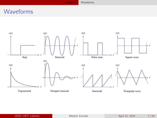
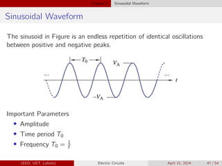
Sinusoidal Waveform
v(t) = VA sin (2πt/T0) V
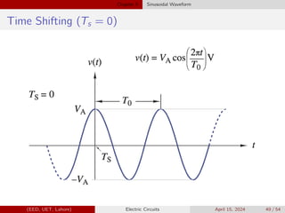
v(t) = VA cos (2πt/T0) V
The general sinusoid is obtained by replacing t by (t − TS).
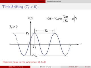
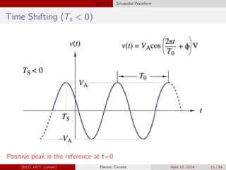
v(t) = VA cos [2π (t − TS) /T0] V
The time-shifting parameter can also be represented by an angle:
v(t) = VA cos [2πt/T0 + φ] V
(EED, UET, Lahore) Electric Circuits April 15, 2024 48 / 54](https://image.slidesharecdn.com/ee100chapter5waveforms-240814093650-81ddea28/85/Waveforms-EE_100_Chapter_5___Waveforms-pdf-48-320.jpg)
![Chapter 5 Sinusoidal Waveform
Alternative Approach
v(t) = VA cos [2πt/T0 + φ] V
Using the identity cos(x + y) = cos(x) cos(y) − sin(x) sin(y),
v(t) = [VA cos φ] cos (2πt/T0) + [−VA sin φ] sin (2πt/T0) V
The quantities inside the brackets are constants; therefore, we can write
the general sinusoid in the following form:
v(t) = a cos (2πt/T0) + b sin (2πt/T0) V
The two amplitude-like parameters a and b have the same units as the
waveform (volts in this case) and are called Fourier coefficients.
a = VA cos φ
b = −VA sin φ
(EED, UET, Lahore) Electric Circuits April 15, 2024 53 / 54](https://image.slidesharecdn.com/ee100chapter5waveforms-240814093650-81ddea28/85/Waveforms-EE_100_Chapter_5___Waveforms-pdf-53-320.jpg)