Downloaded 349 times

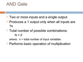
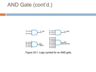
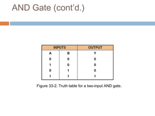
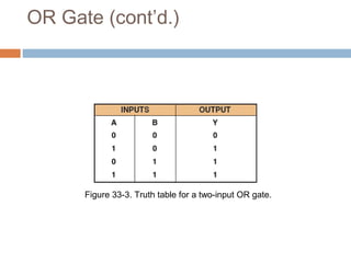
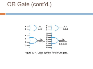
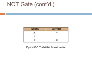
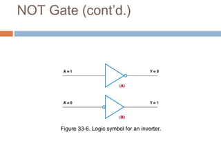
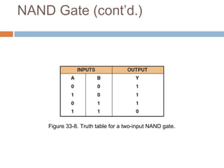
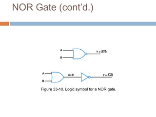

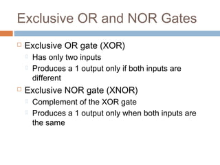
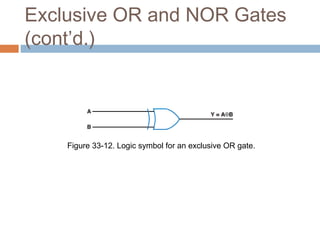
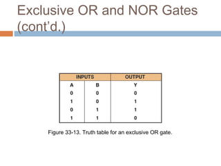
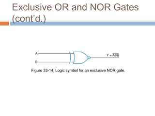


This document describes basic logic gates and their functions. It explains that an AND gate outputs 1 only when all inputs are 1, while an OR gate outputs 1 if any input is 1. A NOT gate inverts the input, and a NAND gate outputs 1 when any input is 0. A NOR gate only outputs 1 when all inputs are 0, and an XOR gate outputs 1 when the inputs are different.