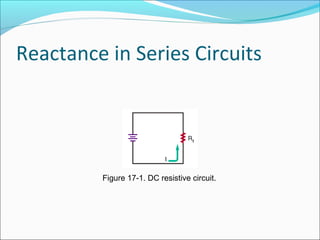
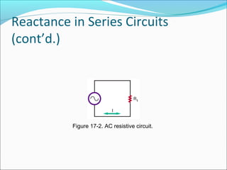
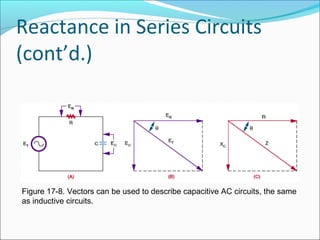
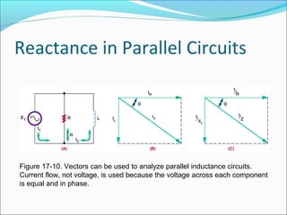
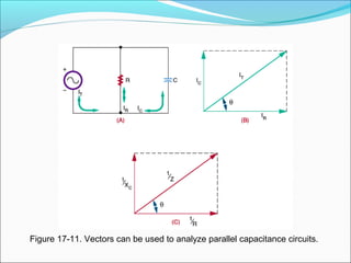
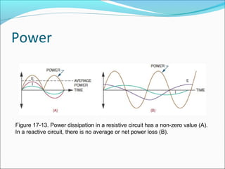
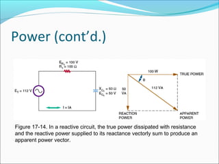
Resonance Circuits
Reactance in Series Circuits
Figure 17-1. DC resistive circuit.
Reactance in Series Circuits
(cont’d.)
Figure 17-2. AC resistive circuit.
Reactance in Series Circuits
(cont’d.)
Figure 17-3. In a resistive AC circuit, current and voltage are in phase.
Reactance in Series Circuits
(cont’d.)
Figure 17-4. Voltage in either RL circuits such as this one or
in RC circuits is not in phase and cannot be added directly.
Reactance in Series Circuits
(cont’d.)
Figure 17-5. Vectors can be used to show the
relationship between voltages in a reactive circuit.
Reactance in Series Circuits
(cont’d.)
Figure 17-7. Vectors can also be used to describe impedance.
Reactance in Series Circuits
(cont’d.)
Figure 17-8. Vectors can be used to describe capacitive AC circuits, the same
as inductive circuits.
Reactance in Parallel Circuits
Figure 17-10. Vectors can be used to analyze parallel inductance circuits.
Current flow, not voltage, is used because the voltage across each component
is equal and in phase.
Figure 17-11. Vectors can be used to analyze parallel capacitance circuits.
Power
Figure 17-13. Power dissipation in a resistive circuit has a non-zero value (A).
In a reactive circuit, there is no average or net power loss (B).
Power (cont’d.)
Figure 17-14. In a reactive circuit, the true power dissipated with resistance
and the reactive power supplied to its reactance vectorly sum to produce an
apparent power vector.
Introduction to Resonance
Resonant circuits
Pass desired frequencies and reject all others
Resonance
When a circuit’s inductive and capacitive reactance are
balanced
Summary
Ohm’s law applies to AC circuits, just as it does to DC
circuits
Vector representation allows the use of trigonometric
functions to determine voltage or current when the
phase angle is known
Resonance is desired for radio frequency in tuning
circuits

resonance circuits

  • 1.
  • 2.
    Reactance in SeriesCircuits Figure 17-1. DC resistive circuit.
  • 3.
    Reactance in SeriesCircuits (cont’d.) Figure 17-2. AC resistive circuit.
  • 4.
    Reactance in SeriesCircuits (cont’d.) Figure 17-3. In a resistive AC circuit, current and voltage are in phase.
  • 5.
    Reactance in SeriesCircuits (cont’d.) Figure 17-4. Voltage in either RL circuits such as this one or in RC circuits is not in phase and cannot be added directly.
  • 6.
    Reactance in SeriesCircuits (cont’d.) Figure 17-5. Vectors can be used to show the relationship between voltages in a reactive circuit.
  • 7.
    Reactance in SeriesCircuits (cont’d.) Figure 17-7. Vectors can also be used to describe impedance.
  • 8.
    Reactance in SeriesCircuits (cont’d.) Figure 17-8. Vectors can be used to describe capacitive AC circuits, the same as inductive circuits.
  • 9.
    Reactance in ParallelCircuits Figure 17-10. Vectors can be used to analyze parallel inductance circuits. Current flow, not voltage, is used because the voltage across each component is equal and in phase.
  • 10.
    Figure 17-11. Vectorscan be used to analyze parallel capacitance circuits.
  • 11.
    Power Figure 17-13. Powerdissipation in a resistive circuit has a non-zero value (A). In a reactive circuit, there is no average or net power loss (B).
  • 12.
    Power (cont’d.) Figure 17-14.In a reactive circuit, the true power dissipated with resistance and the reactive power supplied to its reactance vectorly sum to produce an apparent power vector.
  • 13.
    Introduction to Resonance Resonantcircuits Pass desired frequencies and reject all others Resonance When a circuit’s inductive and capacitive reactance are balanced
  • 14.
    Summary Ohm’s law appliesto AC circuits, just as it does to DC circuits Vector representation allows the use of trigonometric functions to determine voltage or current when the phase angle is known Resonance is desired for radio frequency in tuning circuits