chapter 1 for Computer science introduction to digital logic design and
1.
Chapter 1
Introduction toDigital Systems
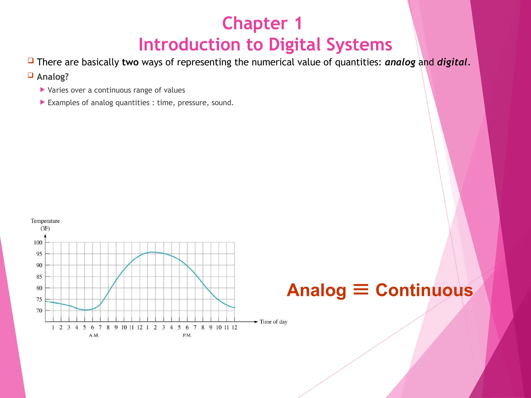
There are basically two ways of representing the numerical value of quantities: analog and digital.
Analog?
Varies over a continuous range of values
Examples of analog quantities : time, pressure, sound.
1
Analog Continuous
2.
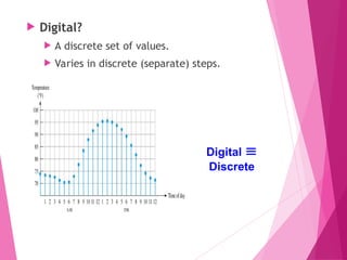
Digital?
Adiscrete set of values.
Varies in discrete (separate) steps.
2
Digital
Discrete
3.
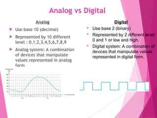
Analog vs Digital
Analog
Use base 10 (decimal)
Represented by 10 different
level : 0,1,2,3,4,5,6,7,8,9
Analog system: A combination
of devices that manipulate
values represented in analog
form
3
Digital
Use base 2 (binary)
Represented by 2 different level:
0 and 1 or low and high.
Digital system: A combination of
devices that manipulate values
represented in digital form.
4.
DIGITAL
Digital technologyis widely used. Examples:
Computers
Manufacturing systems
Medical Science
Transportation
Entertainment
Telecommunications
Basic digital concepts and terminology are introduced
4
5.
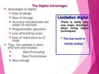
The Digital Advantages
TheDigital Advantages
Advantages of digital
Ease of design
Ease of storage
Accuracy and precision are
easier to maintain
Programmable operation
Less affected by noise
Ease of fabrication on IC
chips
Thus, the systems is more
efficient and reliable:
Data Processing
Data Transmission
Data Storage
5
Limitation digital
Limitation digital
There is really only
one major drawback
when using digital
techniques:
“ The real world is
mainly analog”
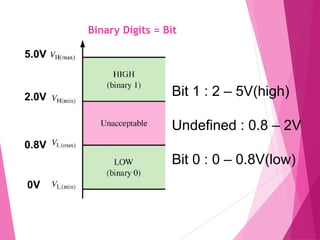
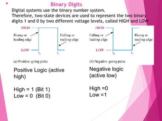
Binary Digits
Digitalsystems use the binary number system.
Therefore, two-state devices are used to represent the two binary
digits 1 and 0 by two different voltage levels, called HIGH and LOW
8
Positive Logic (active
high)
High = 1 (Bit 1)
Low = 0 (Bit 0)
Negative logic
(active low)
High =0
Low =1
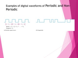
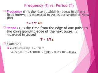
Frequency (f) vs.Period (T)
Frequency (f) is the rate at which it repeat itself at a
fixed interval. Is measured in cycles per second or Hertz
(Hz)
f = 1/T
f = 1/T Hz
Period (T) is the time from the edge of one pulse to
the corresponding edge of the next pulse. Is
measured in second
T = 1/f
T = 1/f s
s
Example :
clock frequency : f = 100Hz,
so, period : T = 1/100Hz = 0.01s = 0.01x 103
= 10 ms
10
11.
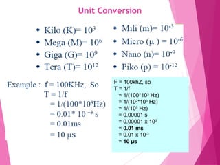
Unit Conversion
11
F =100khZ, so
T = 1/f
= 1/(100*103
Hz)
= 1/(102
*103
Hz)
= 1/(105
Hz)
= 0.00001 s
= 0.00001 x 103
= 0.01 ms
= 0.01 x 10-3
= 10 µs
12.
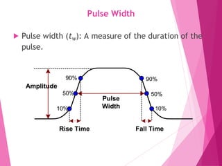
Pulse Width
Pulsewidth (tW): A measure of the duration of the
pulse.
Amplitude
Pulse
Width
Rise Time Fall Time
90%
50%
10%
90%
50%
10%
12
13.
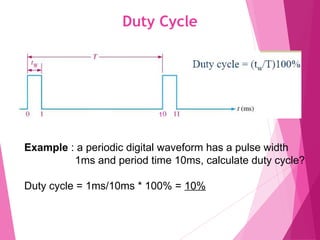
Duty Cycle
13
Example :a periodic digital waveform has a pulse width
1ms and period time 10ms, calculate duty cycle?
Duty cycle = 1ms/10ms * 100% = 10%
1
14.
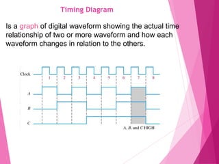
Timing Diagram
14
Is agraph of digital waveform showing the actual time
relationship of two or more waveform and how each
waveform changes in relation to the others.
15.
15
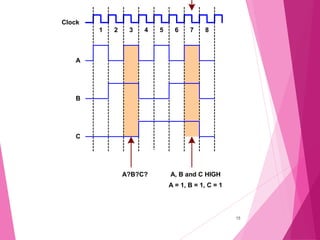
1 2 34 5 6 7 8
A
B
C
Clock
A, B and C HIGH
A = 1, B = 1, C = 1
A?B?C?