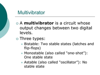
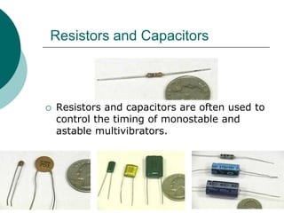
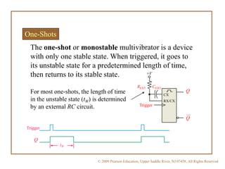
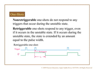
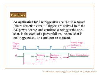
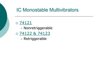
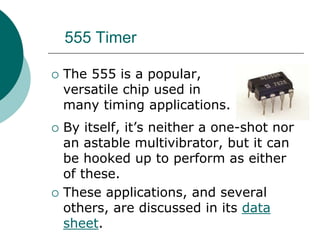
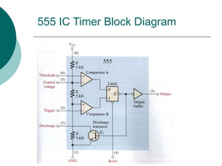
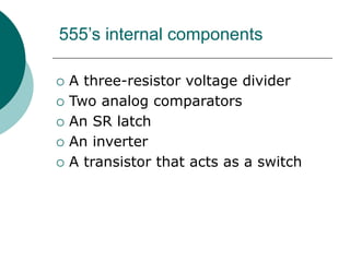
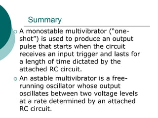
Multivibrator
 A multivibrator is a circuit whose
output changes between two digital
levels.
 Three types:
 Bistable: Two stable states (latches and
flip-flops)
 Monostable (also called “one-shot”):
One stable state
 Astable (also called “oscillator”): No
stable state
More on the Three Types
 Bistable Multivibrator: When placed in
either state, it will stay there indefinitely;
won’t spontaneously switch to the other
state.
 Monostable (“One-shot”): Will stay in its
stable state indefinitely, but if forced into
the other state it will spontaneously
switch back after a certain time.
 Astable (“Oscillator”): From either state it
will spontaneously switch to the other
state after a certain time.
Resistors and Capacitors
 Resistors and capacitors are often used to
control the timing of monostable and
astable multivibrators.
Resistors
 (From EET 1150, DC Circuits)
 Resistors are measured in ohms (Ω).
 Typical values range from 10 Ω to 10 MΩ.
 Value is coded on the body using a color
code. Above, green-blue-red = 5.6 kΩ.
 Schematic symbol:
 (From EET 1150, DC Circuits)
 Capacitors are measured in farads (F).
 Typical values range from 10 pF to 1000 F.
 Value may be printed directly on the body
(as above) or using a numeric code.
 Schematic symbol:
Capacitors
 (From EET 1150, DC Circuits)
 Most capacitors (above) are not polarized: it
doesn’t matter which way you insert them in
a circuit.
 Some capacitors (below) are polarized. Body
markings show which end is negative.
Polarized Capacitors
Capacitor Charge and Discharge
 RC circuit charge and discharge
curves
Capacitor Charge and Discharge
 (From EET 1150, DC Circuits)
 For the circuit on the previous slide,
the time constant is equal to the
product of R times C:
Time constant = RC
 This time constant is a measure of
how quickly the capacitor charges.
 Rule of thumb: The capacitor is fully
charged after about 5 time constants.
© 2009 Pearson Education, Upper Saddle River, NJ 07458. All Rights Reserved
One-Shots
The one-shot or monostable multivibrator is a device
with only one stable state. When triggered, it goes to
its unstable state for a predetermined length of time,
then returns to its stable state.
For most one-shots, the length of time
in the unstable state (tW) is determined
by an external RC circuit. Trigger
CEXTREXT
+V
CX
RX/CX
Q
Q
tW
Trigger
Q
© 2009 Pearson Education, Upper Saddle River, NJ 07458. All Rights Reserved
One-Shots
Retriggerable one-shots respond to any trigger, even
if it occurs in the unstable state. If it occurs during the
unstable state, the state is extended by an amount
equal to the pulse width.
Retriggers
tW
Trigger
Q
Retriggerable one-shot:
Nonretriggerable one-shots do not respond to any
triggers that occur during the unstable state.
© 2009 Pearson Education, Upper Saddle River, NJ 07458. All Rights Reserved
One-Shots
An application for a retriggerable one-shot is a power
failure detection circuit. Triggers are derived from the
AC power source, and continue to retrigger the one-
shot. In the event of a power failure, the one-shot is
not triggered and an alarm can be initiated.
tW
tW
tW
Retriggers Retriggers
Triggers
derived
from ac
Q
Missing trigger
due to power
failure
Power failure indication
IC Monostable Multivibrators
 74121
 Nonretriggerable
 74122 & 74123
 Retriggerable
555 Timer
 The 555 is a popular,
versatile chip used in
many timing applications.
 By itself, it’s neither a one-shot nor
an astable multivibrator, but it can
be hooked up to perform as either
of these.
 These applications, and several
others, are discussed in its data
sheet.
555 Input and Output Pins
 Aside from its power and ground
pins, the 555 has five input pins and
one output pin.
Pin diagram
from datasheet
Logic symbol
from Multisim
© 2009 Pearson Education, Upper Saddle River, NJ 07458. All Rights Reserved
The 555 timer as a monostable multivibrator
The 555 timer can be configured in various ways,
including as a one-shot. A basic one shot is shown. The
pulse width is determined by RAC and is approximately
tW = 1.1RAC.
The trigger is a
negative-going
pulse.
tW = 1.1RAC
© 2009 Pearson Education, Upper Saddle River, NJ 07458. All Rights Reserved
The 555 timer as an astable multivibrator
The 555 can be configured as a basic astable
multivibrator with the circuit shown. In this circuit C
charges through RA and RB. It discharges through only RB.
The time high, time low, and frequency are given by:
𝑡 𝐿𝑂 = 0.693𝑅 𝐵 𝐶
𝑡 𝐻𝐼 = 0.693(𝑅 𝐴 + 𝑅 𝐵)𝐶
𝑓 =
1
𝑡 𝐿𝑂 + 𝑡 𝐻𝐼
555 IC Timer Block Diagram
555’s internal components
 A three-resistor voltage divider
 Two analog comparators
 An SR latch
 An inverter
 A transistor that acts as a switch
Summary
 A monostable multivibrator (“one-
shot”) is used to produce an output
pulse that starts when the circuit
receives an input trigger and lasts for
a length of time dictated by the
attached RC circuit.
 An astable multivibrator is a free-
running oscillator whose output
oscillates between two voltage levels
at a rate determined by an attached
RC circuit.

Mutivibrators

  • 1.
    Multivibrator  A multivibratoris a circuit whose output changes between two digital levels.  Three types:  Bistable: Two stable states (latches and flip-flops)  Monostable (also called “one-shot”): One stable state  Astable (also called “oscillator”): No stable state
  • 2.
    More on theThree Types  Bistable Multivibrator: When placed in either state, it will stay there indefinitely; won’t spontaneously switch to the other state.  Monostable (“One-shot”): Will stay in its stable state indefinitely, but if forced into the other state it will spontaneously switch back after a certain time.  Astable (“Oscillator”): From either state it will spontaneously switch to the other state after a certain time.
  • 3.
    Resistors and Capacitors Resistors and capacitors are often used to control the timing of monostable and astable multivibrators.
  • 4.
    Resistors  (From EET1150, DC Circuits)  Resistors are measured in ohms (Ω).  Typical values range from 10 Ω to 10 MΩ.  Value is coded on the body using a color code. Above, green-blue-red = 5.6 kΩ.  Schematic symbol:
  • 5.
     (From EET1150, DC Circuits)  Capacitors are measured in farads (F).  Typical values range from 10 pF to 1000 F.  Value may be printed directly on the body (as above) or using a numeric code.  Schematic symbol: Capacitors
  • 6.
     (From EET1150, DC Circuits)  Most capacitors (above) are not polarized: it doesn’t matter which way you insert them in a circuit.  Some capacitors (below) are polarized. Body markings show which end is negative. Polarized Capacitors
  • 7.
    Capacitor Charge andDischarge  RC circuit charge and discharge curves
  • 8.
    Capacitor Charge andDischarge  (From EET 1150, DC Circuits)  For the circuit on the previous slide, the time constant is equal to the product of R times C: Time constant = RC  This time constant is a measure of how quickly the capacitor charges.  Rule of thumb: The capacitor is fully charged after about 5 time constants.
  • 9.
    © 2009 PearsonEducation, Upper Saddle River, NJ 07458. All Rights Reserved One-Shots The one-shot or monostable multivibrator is a device with only one stable state. When triggered, it goes to its unstable state for a predetermined length of time, then returns to its stable state. For most one-shots, the length of time in the unstable state (tW) is determined by an external RC circuit. Trigger CEXTREXT +V CX RX/CX Q Q tW Trigger Q
  • 10.
    © 2009 PearsonEducation, Upper Saddle River, NJ 07458. All Rights Reserved One-Shots Retriggerable one-shots respond to any trigger, even if it occurs in the unstable state. If it occurs during the unstable state, the state is extended by an amount equal to the pulse width. Retriggers tW Trigger Q Retriggerable one-shot: Nonretriggerable one-shots do not respond to any triggers that occur during the unstable state.
  • 11.
    © 2009 PearsonEducation, Upper Saddle River, NJ 07458. All Rights Reserved One-Shots An application for a retriggerable one-shot is a power failure detection circuit. Triggers are derived from the AC power source, and continue to retrigger the one- shot. In the event of a power failure, the one-shot is not triggered and an alarm can be initiated. tW tW tW Retriggers Retriggers Triggers derived from ac Q Missing trigger due to power failure Power failure indication
  • 12.
    IC Monostable Multivibrators 74121  Nonretriggerable  74122 & 74123  Retriggerable
  • 13.
    555 Timer  The555 is a popular, versatile chip used in many timing applications.  By itself, it’s neither a one-shot nor an astable multivibrator, but it can be hooked up to perform as either of these.  These applications, and several others, are discussed in its data sheet.
  • 14.
    555 Input andOutput Pins  Aside from its power and ground pins, the 555 has five input pins and one output pin. Pin diagram from datasheet Logic symbol from Multisim
  • 15.
    © 2009 PearsonEducation, Upper Saddle River, NJ 07458. All Rights Reserved The 555 timer as a monostable multivibrator The 555 timer can be configured in various ways, including as a one-shot. A basic one shot is shown. The pulse width is determined by RAC and is approximately tW = 1.1RAC. The trigger is a negative-going pulse. tW = 1.1RAC
  • 16.
    © 2009 PearsonEducation, Upper Saddle River, NJ 07458. All Rights Reserved The 555 timer as an astable multivibrator The 555 can be configured as a basic astable multivibrator with the circuit shown. In this circuit C charges through RA and RB. It discharges through only RB. The time high, time low, and frequency are given by: 𝑡 𝐿𝑂 = 0.693𝑅 𝐵 𝐶 𝑡 𝐻𝐼 = 0.693(𝑅 𝐴 + 𝑅 𝐵)𝐶 𝑓 = 1 𝑡 𝐿𝑂 + 𝑡 𝐻𝐼
  • 17.
    555 IC TimerBlock Diagram
  • 18.
    555’s internal components A three-resistor voltage divider  Two analog comparators  An SR latch  An inverter  A transistor that acts as a switch
  • 19.
    Summary  A monostablemultivibrator (“one- shot”) is used to produce an output pulse that starts when the circuit receives an input trigger and lasts for a length of time dictated by the attached RC circuit.  An astable multivibrator is a free- running oscillator whose output oscillates between two voltage levels at a rate determined by an attached RC circuit.