Downloaded 109 times

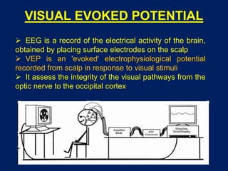
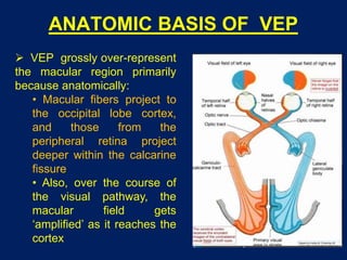
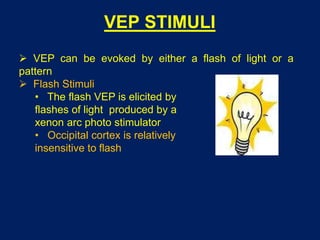
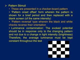
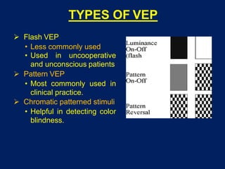

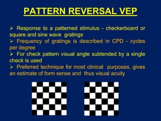
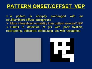


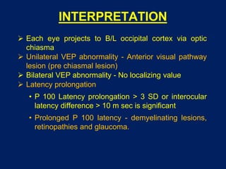


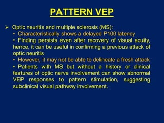

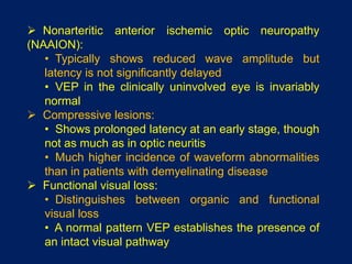


This document discusses visual evoked potentials (VEP), which assess the integrity of the visual pathways from the optic nerve to the occipital cortex. VEP can be evoked by flashes of light or patterned stimuli, with pattern VEP being most commonly used clinically. Pattern VEP involves presenting a checkerboard pattern and measuring the response to pattern onset/offset or reversal. Clinical applications of VEP include evaluating optic neuritis, multiple sclerosis, anterior ischemic optic neuropathy, and compressive lesions, as well as distinguishing organic from functional visual loss.


