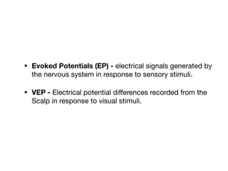
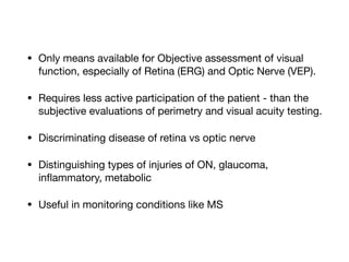
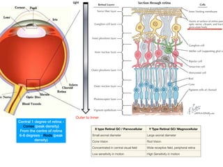
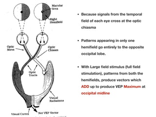
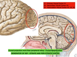
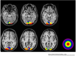
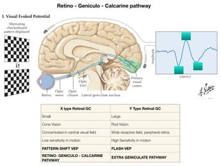
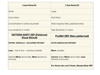
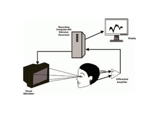
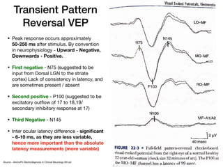
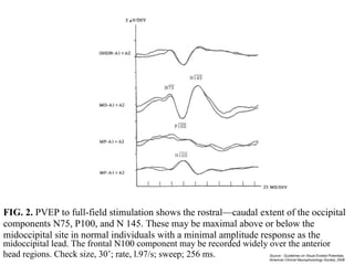
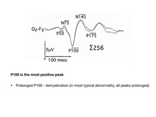
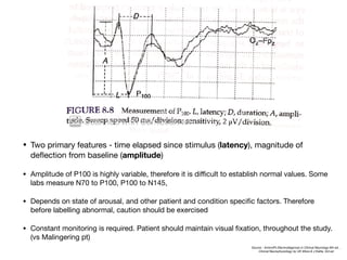
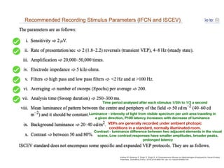
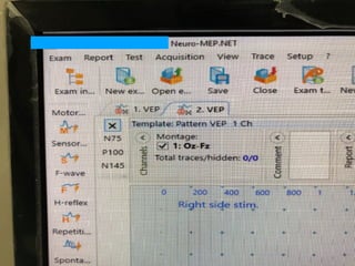
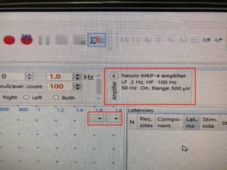
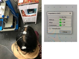
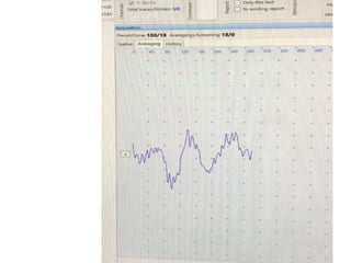
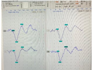
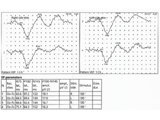
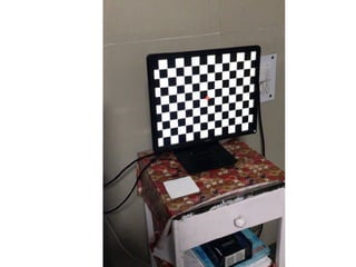
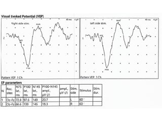
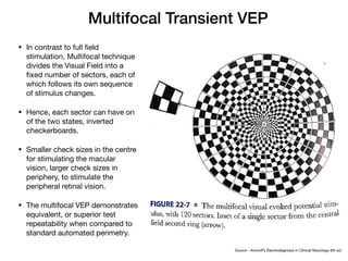
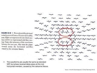
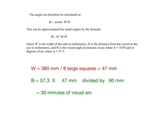
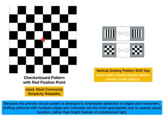
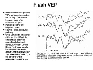
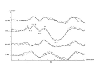
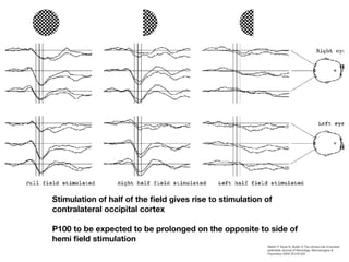
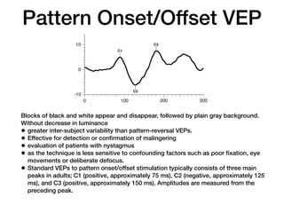
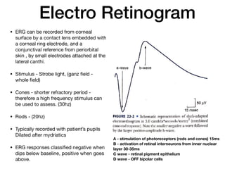
SlideShare a Scribd company logo
Visual Evoked
Potential
Presenter - Dr. Rahul Jain
Moderator - Dr. B. K. Bajaj
• Evoked Potentials (EP) - electrical signals generated by
the nervous system in response to sensory stimuli. 

• VEP - Electrical potential differences recorded from the
Scalp in response to visual stimuli.
• Only means available for Objective assessment of visual
function, especially of Retina (ERG) and Optic Nerve (VEP).

• Requires less active participation of the patient - than the
subjective evaluations of perimetry and visual acuity testing. 

• Discriminating disease of retina vs optic nerve

• Distinguishing types of injuries of ON, glaucoma,
inflammatory, metabolic

• Useful in monitoring conditions like MS
CLINICAL POINT
Ganglion cell layer
Nerve fiber layer
Inner plexiform layer
Inner nuclear layer
Outer plexiform layer
Outer nuclear layer
Photoreceptor layer
Pigment epithelium
Cells
Inner limiting membrane
Axons at surface of retina pass
optic nerve, chiasm, and tract
geniculate body
Ganglion cell
Müller cell (supporting glial ce
Amacrine cell
Bipolar cell
Horizontal cell
Rod
Cone
Pigment cells of choroid
Section through retina
Retinal Layers
14.25 THE RETINA: RETINAL LAYERS
The retina is a tissue-paper-thin piece of CNS tissue that con-
tains the photoreceptors; it is attached to the vascular tunic at
the ora serrata. The layers of the retina in the interior of the
eyeball are oriented from outer to inner. The pigment epithe-
lium is at the outer margin, followed by the outer nuclear layer
(photoreceptors), the inner nuclear layer (bipolar neurons,
amacrine and horizontal cells), and the ganglion cell layer. The
outer and inner plexiform layers are the zones of synaptic
connectivity. The ganglion cell axons form an inner nerve
metric midpoint. The fovea consists purel
vision (photopic); these cone projection
involve very little convergence. In the fove
one-to-one-to-one relationship among
neurons, and ganglion cells. The periphe
ceptors are mainly rods, for night vision
huge convergence of rods onto bipolar neu
converge onto single ganglion cells. T
achieved in the fovea, the region for color
Outer to Inner
X type Retinal GC / Parvocellular Y Type Retinal GC/ Magnocellular
Small axonal diameter Large axonal diameter
Cone Vision Rod Vision
Concentrated in central visual field Wide receptive field, peripheral retina
Low sensitivity in motion High Sensitivity in motion
Central 1 degree of retina -
Cones (peak density)
From the centre of retina
6-8 degrees - Rods (peak
density)
• Because signals from the temporal
field of each eye cross at the optic
chiasma
• Patterns appearing in only one
hemifield go entirely to the opposite
occipital lobe.
• With Large field stimulus (full field
stimulation), patterns from both the
hemifields, produce vectors which
ADD up to produce VEP Maximum at
occipital midline
Left eye Right eye
Chiasm
Chiasm
Prechiasmatic
Postchiasmatic
Optic tract
Optic
nerve
(Optic nerve)
Optic tract
Crossed
(nasal)
fibers
Uncrossed
(temporal)
fibers
Key
Optic radiations
Occipital cortex
Superior
nasal fibers
Superior
Temporal
Nasal
Retinal
fibers
Nasal
Inferior
Temporal
Inferior
nasal fibers
Inferior nasal fibers
decussate in anterior
chiasm and then
project into optic tract
as anterior fibers
Superior view
Optic pathway
(superior view)
with
E.Hatton
2:1
Limbic cingulate cortex
Thalamus
Pituitary gland
bes and functional areas
Pons
mental motor cortex
Medulla oblongata
Frontal
Limbic
Primary motor cortex
Parietal
Occipital
Precentral sulcus
Paracentral lobule
Somatosensory association cortex
Corpus callosum
Visual association cortex
Calcarine fissure
Primary visual cortex
Cerebellum
UB
LB
A. Lobes and functional areas
Pons
Medulla oblongata
Cereb
8
9
6 4
7
7
23
19
18
17
17
18
31
24
32
32
10
12 25
33
3
1 2
RAIN:
unique architec-
6
6
6
4
3,1,2
3,1,2
3,1,2
22
22
22
41
42
40
40
40
39
39
37
37
37
37
21
20
20
21
5
5
7
7 7
19
19
19
19
19
18
18
18
17
4
4
1909. His numbering of cortical areas is still used as a short-
hand for describing the functional regions of the cortex, par-
ticularly those related to sensory functions. Some overlap
17 - Primary Visual Cortex V1
18 - Secondary Visual Cortex V2
19 - Association Visual Cortex V3, V4, V5
UB
LB
Foveal projection more than peripheral retina - Foveal Magnification
GENERATOR OF VEP - STRIATE AND PERI STRIATE CORTEX
VISUALLY EVOKED POTENTIALS BY DONNELL J. CREEL,
https://webvision.med.utah.edu/book/electrophysiology/visually-evoked-potentials/
Retina
Alternating
checkerboard
pattern displayed
Optic
nerve
Optic
chiasm
Optic
tract
Lateral geniculate nucleus
Cochlear
Series of
Inferior colliculus
Latency
Amplitude
Latency
Amplitude
Lateral lemniscus
Medial geniculate body
Acoustic area of
temporal lobe cortex
Primary
visual
cortex
P1
N1
I
VI
VII
II III
IV
V
VI
VII
N2
I. Visual Evoked Potential
II. Brainstem Auditory Evoked Potential
Retino - Geniculo - Calcarine pathway
X type Retinal GC Y Type Retinal GC
Small Large
Cone Vision Rod Vision
Concentrated in central visual field Wide receptive field, peripheral retina
Low sensitivity in motion High Sensitivity in motion
PATTERN SHIFT VEP FLASH VEP
RETINO- GENICULO - CALCARINE
PATHWAY
EXTRA GENICULATE PATHWAY
X type Retinal GC Y Type Retinal GC
Small Large
Cone Vision Rod Vision
Concentrated in central visual field Wide receptive field, peripheral retina
Low sensitivity in motion High Sensitivity in motion
PATTERN SHIFT VEP (Patterned
Visual Stimuli)
FLASH VEP (Non patterned)
RETINO- GENICULO - CALCARINE PATHWAY EXTRA GENICULATE PATHWAY
Less - Inter & Intra - individual variability More variability
Detects Minor abnormality, More Sensitive &
Accurate
Cannot detect Minor abnormality, Less
Sensitive & Accurate
For those who can’t fixate, Steady State VEP
Pre-Test Evaluation
• Explain the procedure, co-operation.

• Avoid Hair Spray or Oil after last hair wash

• Usual glasses, to be Worn during the test

• Ophthalmological Exam results to be reviewed. - Visual
acuity, pupillary diameter, visual field

• Avoid any miotic/ mydriatic drug 12hrs before the test
Procedure
• Standard disc EEG electrodes used.

• Skin should be prepared by abrading and degreasing.

• Two Channel vs Four Channel VEP (Electrode Placement)
Electrode Placement
2 channel VEP
Channel 1 - Oz - Fz

Channel 2 - Oz - linked ear
4 channel VEP
Channel 1 - Oz - Fz

Channel 2 - Pz - Fz

Channel 3 - L5 - Fz

Channel 4 - R5 - Fz
Impedance < 5 kilo ohms
Oz - actually located at the middle point of Variation Range of Calcarine fissure
12 cm above the nasion
Reference Electrode
Recording Electrode
5 cm above the Inion
International 10 - 20 System
• Oz - 3-4cm above inion (10% of
distance between inion and
nation, which is about 3-4 cm in
normal adults)

• Fz - 11cm above nasion

• O1, O2 - 2.5 cm lateral to Oz

• A1 A2 ear

• Cz - ground
Queens Montage
• MO (Mid Occipital) - 5cm above
inion, in midline

• MF (mid frontal) - 12cm above
nasion, in midline

• LO, RO (left right occiptial) - 5cm
left and right of MO

• A1/A2 - ear

• Ground - Vertex
Source - Guidelines on Visual Evoked Potentials,
American Clinical Neurophysiology Society, 2008
Transient Pattern
Reversal VEP
• Peak response occurs approximately
50-250 ms after stimulus. By convention
in neurophysiology - Upward - Negative,
Downwards - Positive.

• First negative - N75 (suggested to be
input from Dorsal LGN to the striate
cortex) Lack of consistency in latency, and
are sometimes present / absent

• Second positive - P100 (suggested to be
excitatory outflow of 17 to 18,19/
secondary inhibitory response at 17)

• Third Negative - N145

• Inter ocular latency difference - significant
- 6-10 ms, as they are less variable,
hence more important than the absolute
latency measurements (more variable)
Source - Aminoff’s Electrodiagnosis in Clinical Neurology 6th ed.
FIG. 2. PVEP to full-field stimulation shows the rostral—caudal extent of the occipital
components N75, P100, and N 145. These may be maximal above or below the
midoccipital site in normal individuals with a minimal amplitude response as the
midoccipital lead. The frontal N100 component may be recorded widely over the anterior
ad . C c , 30 ; a , .97/ ; ; 256 . Source - Guidelines on Visual Evoked Potentials,
American Clinical Neurophysiology Society, 2008
P100 is the most positive peak
• Prolonged P100 - demyelination (in most typical abnormality, all peaks prolonged)
• Two primary features - time elapsed since stimulus (latency), magnitude of
deflection from baseline (amplitude)

• Amplitude of P100 is highly variable, therefore it is difficult to establish normal values. Some
labs measure N70 to P100, P100 to N145, 

• Depends on state of arousal, and other patient and condition specific factors. Therefore
before labelling abnormal, caution should be exercised

• Constant monitoring is required. Patient should maintain visual fixation, throughout the study.
(vs Malingering pt)
Source - Aminoff’s Electrodiagnosis in Clinical Neurology 6th ed. ,
Clinical Neurophysiology by UK Misra & J Kalita, 3rd ed
• Average of 100 - 200 stimuli - one response. With low
amplitudes upto 400 stimuli. 

• The values can be compared to the standard normative
data. Peak latencies are more consistent, than amplitudes. 

• At least 2 responses to be recorded. The P100 latency
measured in these should be within 2.5 ms difference,
(>6-10ms abnormality), in between - technical
difference.
• Peak to peak amplitude of N75 - P100
Kothari R, Bokariya P, Singh S, Singh R. A Comprehensive Review on Methodologies Employed for Visual Evoked
Potentials. Scientifica (Cairo). 2016;2016:9852194. doi:10.1155/2016/9852194
Time period analysed after each stimulus 1/5th to 1/2 a second
Luminance - intensity of light from visible spectrum per unit area traveling in
a given direction, P100 latency increases with decrease of luminance
VEPs are generally recorded under ambient photopic
conditions in a standard, normally illuminated room.
Contrast - luminance difference between two adjacent elements in the visual
scene, Low contrast responses have smaller amplitudes, broader peaks,
prolonged latency
Produces reversal pattern every 500ms/0.5 s
• Routine Traditional VEP, done in Pattern Shift,
checkerboard pattern is FULL FIELD STIMULATION.

• That means, the Stimulus varies consistently ACROSS A
LARGE PORTION OF THE VISUAL FIELD.
Abberant
waveform
• A VEP waveform is considered
aberrant if it can be recorded
Reproducibly but a P100 peak can
not be identified. 

• Many of aberrant responses,
contain too many peaks, rather than
too few. 

• W shaped P100 - bifid P100 - when
frontal N100 and occipital P100 are
asynchronous. This is seen only in
frontal or central reference. i.e. Oz-
Fpz / Oz - Pz

• Can be seen normally in Oz - A1
leads. (occipital leads)

• Can be abolished by asking the
patient to look at the upper edge of
the pattern, rather than central.
Normal
Normal
Supernumerary
P175 etc. -
Transient
oscillations of
occipital cortex
Walsh P, Kane N, Butler S The clinical role of evoked potentials Journal of Neurology, Neurosurgery & Psychiatry 2005;76:ii16-ii22.
Multifocal Transient VEP
• In contrast to full field
stimulation, Multifocal technique
divides the Visual Field into a
fixed number of sectors, each of
which follows its own sequence
of stimulus changes. 

• Hence, each sector can have on
of the two states, inverted
checkerboards. 

• Smaller check sizes in the centre
for stimulating the macular
vision, larger check sizes in
periphery, to stimulate the
peripheral retinal vision. 

• The multifocal VEP demonstrates
equivalent, or superior test
repeatability when compared to
standard automated perimetry.
Source - Aminoff’s Electrodiagnosis in Clinical Neurology 6th ed.
• The waveforms are usually the same as standard
VEP, but phase reversal takes place at the mid
horizontal meridian, caused by the calcarine fissure
Source - Aminoff’s Electrodiagnosis in Clinical Neurology 6th ed.
a. Full field VEP recording
from Oz - Fpz, 53 yr old
woman, leading to
temporal dispersion
which is difficult to
interpret

b. Multifocal VEP confirms
abnormality by
demonstrating central
amplitude decrement in
left eye (blue)
Source - Aminoff’s
Electrodiagnosis in Clinical
Neurology 6th ed.
P100 on standard pattern reversal VEP -
178, 179 normal brain mri
Normal P100 latency on multifocal VEP
Source - Aminoff’s Electrodiagnosis in Clinical Neurology 6th ed.
Stimulation Patterns
• Pattern Shift VEP - Checker Board pattern.
• The size of the stimulus, at the retina will depend on its size on the monitor, and
the distance of the subject from the screen. 

• The total stimulus size will determine the area of the visual field subject to
stimulation, and check size will impact the neuronal cell population which is
generating the response. 

• Hence, larger check sizes, will stimulate more of peripherally located RGCs

• Smaller check sizes, will stimulate more of centrally located RGCs

• But smaller check sizes - have risk of error due to refractive errors. Larger check
sizes, will not produce adequate central field stimulation. (pattern shift VEP)

• IFCN recommends, check size that subtend 24 - 32 minutes of visual arc.
W = 380 mm / 8 large squares = 47 mm 

B = 57.3 X 47 mm divided by 90 mm 

= 30 minutes of visual arc
subtended by both the vertical and horizontal dimensions. The visual angle subtended by
an indi id al elemen f he a e n a he bjec e e i e e ed in ei he min e
degrees of arc. The tangent of the visual angle is equal to the check width divided by the
distance from the eye to the screen.
The angle can therefore be calculated as:
B = arctan W/D
This can be approximated for small angles by the formula:
B= A* W/D
where W is the width of the unit in millimeters, D is the distance from the screen to the
eye in millimeters, and B is the visual angle in minutes of arc when A = 3438 and in
degrees of arc when A = 57.3.
Size of stimulus field. The size of the total stimulus field is specified by the visual angle
i b end a he bjec e e, mea ed a de c ibed ab e f individual pattern units.
Location and designation of stimulus field types. A fixation point must be provided for
the subject that is distinct from the reversing pattern itself. The location of the fixation
in i h ega d he im l field de e mine he egi n f he bjec i al field
to be stimulated. A pattern that extends equally to both sides of the fixation point is
referred to as a full-field stimulus. A pattern restricted to a small region of central vision,
such as 2-4 , with central fixation is designated a central-field stimulus. A pattern
presented to one side of the fixation point in one-half of the visual field, such as right half
or left half, is designated a half-field or hemi-field stimulus. A pattern presented to a
small sector of the visual field is designated a partial-field stimulus, with the location
described relative to the fixation point. Half-field stimuli presented in an alternating
fashion with reversal of left and right half fields sequentially, with a central fixation spot,
are designated alternating half field stimuli.
Whenever half-field or partial-field stimuli are used, the fixation point should be
displaced to the nonstimulated visual field by a small amount, such as 1 check width of
10. This helps prevent stimulation of both retinal hemifields or regions outside the
Checkerboard Pattern
with Red Fixation Point
Vertical Grating Pattern Shift Vep
Used when checkerboard pattern
misses trivial defects.
Used. Most Commonly
Simplicity Reliability
Because the primary visual system is arranged to emphasise detection of edges and movement,
shifting patterns with multiple edges and contrasts are the most appropriate way to assess visual
function, rather than bright flashes of unpatterned light.
• Stimulus Field Types - Fixation point is provided for the
subject that is distinct from the reversing pattern itself. 

1. Full field stimulation

2. Central field stimulation

3. Partial field stimulation (not yet useful in clinical
practice)

4. Alternating half field stimulation (not yet useful in
clinical practice)
Anterior to chiasma
Posterior to chiasma
Full Field Stimulation
Left eye Right eye
Chiasm
Chiasm
Prechiasmatic
Postchiasmatic
Optic tract
Optic
nerve
(Optic nerve)
Optic tract
Crossed
(nasal)
fibers
Uncrossed
(temporal)
fibers
Key
Optic radiations
Occipital cortex
Superior
nasal fibers
Superior
Temporal
Nasal
Retinal
fibers
Nasal
Inferior
Temporal
Inferior
nasal fibers
Inferior nasal fibers
decussate in anterior
chiasm and then
project into optic tract
as anterior fibers
Superior view
Optic pathway
(superior view)
with
E.Hatton
• Most sensitive in detecting visual system Anterior
to Optic Chiasma
• Majority of P100 responses arise in neural
elements of the eye subserving the central 8-10
degrees of the visual field.
• Lesions that produce half or partial visual field
deficits but that spare much of central vision will
usually not produce significant changes in P100
response latency or amplitude. Such partial lesions
in prechiasmal, postchiasmal, or chiasmal
locations may produce changes in response
topography, but are best tested for using partial
visual field stimulation
Performed Mono-ocularly
Visual Fixation should be centre of the screen (red
dot)
Flash VEP
• More variable than pattern
VEPs across subjects, but
are usually quite similar
between eyes of an
individual subject.
• Multiple positive and
negative peaks.
• Source - extra geniculate
pathway
• Great variability, limits their
utility, as it is difficult to
differentiate between
normal and abnormal
• Hence, American Clinical
Neurophysiology society
has advised that ONLY
COMPLETE ABSENCE OF
A FLASH RESPONSE CAN
BE CONSIDERED
DEFINITELY ABNORMAL.
•They are useful for patients who are unable or unwilling to
cooperate for pattern VEPs, and when optical factors
such as media opacities prevent the valid use of pattern
stimuli, INFANTS
•Provide rudimentary information, only that the visual
information is reaching the brain.
•Can be done with both eyes closed
•Can be done with opacity of the media
•Not affected by refractive errors
•Preservation of response of FVEP suggests that visual
pathways are at least partially intact, absence indicates
no useful visual function.
•Asymmetry of FVEP may occur at site of structural
lesions.
• The VEP to flash stimulation consists of a series of negative and
positive waves. The earliest detectable component has a peak time
of approximately 30 ms poststimulus and components are
recordable with peak latencies of up to 300 ms. Peaks are
designated as negative and positive in a numerical sequence.
• This nomenclature is recommended to differentiate the flash VEP
from the pattern-reversal VEP. The most robust components of the
flash VEP are the N2 and P2 peaks. Measurements of P2 amplitude
should be made from the positive P2 peak at around 120 ms to the
preceding N2 negative peak at around 90 ms.
• Flash rate - 1 HZ
Note that with a
e is recorded Fig. 4 A normal flash VEP
123
Note that with a
e is recorded Fig. 4 A normal flash VEP
123
124
124
130
130
90
90
cs often make it difficult to compare specific response components betwe
ubjects.
ash VEP to LED goggle stimulation. Response waveforms may be quite
tency and amplitude abnormalities must be interpreted with caution (see
Stimulation of half of the field gives rise to stimulation of
contralateral occipital cortex
P100 to be expected to be prolonged on the opposite to side of
hemi field stimulation
Walsh P, Kane N, Butler S The clinical role of evoked
potentials Journal of Neurology, Neurosurgery &
Psychiatry 2005;76:ii16-ii22.
Pattern Onset/Offset VEP
Blocks of black and white appear and disappear, followed by plain gray background.
Without decrease in luminance
• greater inter-subject variability than pattern-reversal VEPs.
• Effective for detection or confirmation of malingering
• evaluation of patients with nystagmus
• as the technique is less sensitive to confounding factors such as poor fixation, eye
movements or deliberate defocus.
• Standard VEPs to pattern onset/offset stimulation typically consists of three main
peaks in adults; C1 (positive, approximately 75 ms), C2 (negative, approximately 125
ms), and C3 (positive, approximately 150 ms). Amplitudes are measured from the
preceding peak.
mately 150 ms) (see Fig. 3). Amplitudes are mea-
sured from the preceding peak.
comparison of amplitud
the sensitivity of the V
Fig. 3 A normal pattern onset/offset VEP. Note that with a
300 ms sweep only the pattern onset response is recorded Fig. 4 A normal flash VEP
• Stimulation rate - 4-8 Hz
• The responses overlap each other, and
appear as sinusoidal wave form, which
persist during the period of stimulation.
• Also known as Repetitive Evoked
Potentials.
• Repetitive evoked potentials whose
constituent discrete frequency
components remain constant in
amplitude and phase over an infinitely
long time period.
• Children
Source - Clinical Neurophysiology by UK
Misra & J Kalita, 3rd ed
Steady State VEP’s
Factors affecting VEP
• Not affected by direction of change of checks in
checkerboard pattern. Horizontal or Vertical

• Size of checks - Smaller check size - largest peak
amplitude, smallest peak latency.
• A person with good visual acuity - produces shortest
latency and largest amp. With Small check size, person
with poor visual acuity - with Large check size.
Patient Factors
• Sex - P100 latencies, shorter for women than men

• Age - multifocal VEP latency, increases with age, particularly in men, (@ 2.5
ms/ decade after 5th decade)

• Pupil size - pupil dilatation, will reduce P100 latency, mainly in Full Field
Pattern stimulation and vice versa, not in Full field flash VEP. Standard -
recording with pupils normal. (dilatation - more light, constriction - less light)

Average pupillary constriction of 1.75mm increases average latency by 4.6ms. 

• Eye Dominance - Dominant eye - shorter latency, higher amplitude

• Eye Movement - reduced P100 amplitude, Latency not affected. eg.
nystagmus patients

• Body Temp - only in demyelinating lesions, like MS. 

• Some studies have shown, P100 latency to decrease when concentrating
more
Source - Clinical Neurophysiology by UK
Misra & J Kalita, 3rd ed
Usefulness
• Disease of anterior optic pathway may produce prolonged
P100 latencies without detectable alteration in Visual
Acuity, Colour Vision, Pupillary Reactivity, Fundoscopy, or
Perimetry. 

• If Visual Acuity is decreased, and PVEP is normal, it is
very unlikely that optic nerve or chiasma is the lesion.
Diseases
1. Multiple Sclerosis
• Screening for Asymptomatic Lesions in MS is the most
common use. (eg. dissemination in space)

• It has been calculated that a plaque of 1 cm in size , can
lead to P100 delay of about 25 ms. 

• Classical pattern - Assymetrical prolongation of P100
latency, with relative preservation of amplitudes.
• No relationship between VEP and Visual Clinical
complaints was found.
2. NMO
• Unrecordable P100 waveform, and reduced amplitude of
P100 have reported to be characteristic unlike prolonged
P100 latency and normal P100 amplitude in MS.
3. Optic Neuritis
• If in Uni Ocular ON, VEP is prolonged only on the affected
side, not on opposite side, lesser chances of it to be MS.

• Optic neuropathy is found in peripheral neuropathies like -
CMT, giant axonal neuropathy, neuropathy associated
with macroglobulinemia
4. Ischemic Optic
Neuropathy
• Reduction of P100 amplitude, before latency prolonged.
Other
Demyelinating diseases like 

• Adreno-Leuko dystrophy
• Meta-chromatic Leuko dystrophy
• Hereditary spastic paraparesis
Vitamin B12 deficiency - asymmetric, bilateral prolongation of
P100 latency. 

Vitamin E deficiency in patients with Abetalipoproteinemia
Optic Neuropathy in HIV patients.

Alcohol, Tobacco
CO poisoning, reduced amplitude and prolonged latency

Ethambutol, Desferoxamine, Quinine
Vigabatrin, Valproate
Amiodarone
• Not been found to be useful in Cortical Lesions. 

• Abnormal in Optic Nerve Glioma, NF1
Compressive lesions affecting VEP
• Papilledema - later stages, when it becomes severe
enough to compress the optic nerve

• Raised ICT, hydrocephalus, pseudotumor cerebri

• Extrinsic compression of the Anterior Chiasmal pathway
results in Loss of amplitude, destruction of wave form,
prolonged P100 latency. (latency prolongation less as
compared to demyelinating disorders).
• Most imp. Differential for optic neuritis is retinal disorder -
central serous retinopathy. 

• Many patients have been labelled as MS in the past
falsely, due to prolonged VEP, having CSR

• CSR resolves spontaneously.

• PVEP delays can be seen with a variety of other acute
and chronic retinal disorders. Hence, complete
ophthalmological examination is mandatory.
Electro Retinogram
• ERG can be recorded from corneal
surface by a contact lens embedded with
a corneal ring electrode, and a
conjunctival reference from periorbital
skin , by small electrodes attached at the
lateral canthi.

• Stimulus - Strobe light, (ganz field -
whole field)

• Cones - shorter refractory period -
therefore a high frequency stimulus can
be used to assess. (30hz)

• Rods - (20hz)

• Typically recorded with patient’s pupils
Dilated after mydriatics

• ERG responses classified negative when
dips below baseline, positive when goes
above.
A - stimulation of photoreceptors (rods and cones) 15ms
B - activation of retinal interneurons from inner nuclear
layer 30-35ms
C wave - retinal pigment epithelium
D wave - OFF bipolar cells
• Pattern Reversal ERG can be recorded with alternating
checkerboard stimulus. 

• PERG - characterised by negative wave around 50ms N50 and
positive deflection at around 95ms P95

• P95 is thought to reflect the b wave - activation of RGC. 

• It was found that in individuals with abnormal VEP, P95 was
prolonged, but P50 was almost always preserved. But in those
with normal VEP, both could be prolonged. 

• Hence also distinguishes abnormality between Photoreceptors and
RGCs.
Thank You

More Related Content

What's hot

Introduction, history and neurophysiologic basis of vep
Introduction, history and neurophysiologic basis of vepIntroduction, history and neurophysiologic basis of vep
Introduction, history and neurophysiologic basis of vep
kalpanabhandari19
 

What's hot (20)

Blink reflex
Blink reflex Blink reflex
Blink reflex
 
VEP for the 21st Century
VEP for the 21st CenturyVEP for the 21st Century
VEP for the 21st Century
 
Saccadic Eye Movement
Saccadic Eye Movement Saccadic Eye Movement
Saccadic Eye Movement
 
Supranuclear control of eye movements
Supranuclear control of eye movements Supranuclear control of eye movements
Supranuclear control of eye movements
 
Blink reflex 1
Blink reflex 1Blink reflex 1
Blink reflex 1
 
Brainstem auditory evoked potentials (baep)
Brainstem auditory evoked potentials (baep)Brainstem auditory evoked potentials (baep)
Brainstem auditory evoked potentials (baep)
 
PLEDS
PLEDSPLEDS
PLEDS
 
BAEP, BERA, BEP, Brainstem auditory evoked potential By Murtaza Syed
BAEP, BERA, BEP, Brainstem auditory evoked potential By Murtaza SyedBAEP, BERA, BEP, Brainstem auditory evoked potential By Murtaza Syed
BAEP, BERA, BEP, Brainstem auditory evoked potential By Murtaza Syed
 
Neuroophthalmology
NeuroophthalmologyNeuroophthalmology
Neuroophthalmology
 
Optic coherence tomography
Optic coherence tomographyOptic coherence tomography
Optic coherence tomography
 
Introduction, history and neurophysiologic basis of vep
Introduction, history and neurophysiologic basis of vepIntroduction, history and neurophysiologic basis of vep
Introduction, history and neurophysiologic basis of vep
 
EEG Variants By IM
EEG Variants By IMEEG Variants By IM
EEG Variants By IM
 
Supranuclear control of gaze
Supranuclear control of gazeSupranuclear control of gaze
Supranuclear control of gaze
 
Chronic progressive external ophthalmoplegia
Chronic progressive external ophthalmoplegiaChronic progressive external ophthalmoplegia
Chronic progressive external ophthalmoplegia
 
Supra nuclear eye movements
Supra nuclear eye movementsSupra nuclear eye movements
Supra nuclear eye movements
 
Nystagmus
NystagmusNystagmus
Nystagmus
 
Neuro-ophthalmology
Neuro-ophthalmology Neuro-ophthalmology
Neuro-ophthalmology
 
Ssep pathways
Ssep pathwaysSsep pathways
Ssep pathways
 
Horner's syndrome and Internuclear ophthalmoplegia
Horner's syndrome and Internuclear ophthalmoplegiaHorner's syndrome and Internuclear ophthalmoplegia
Horner's syndrome and Internuclear ophthalmoplegia
 
ELECTROOCULOGRAM (EOG) - Basics
ELECTROOCULOGRAM (EOG) - BasicsELECTROOCULOGRAM (EOG) - Basics
ELECTROOCULOGRAM (EOG) - Basics
 

Similar to Visual Evoked Potentials

Visual evoked potential and BAER
Visual evoked potential and BAERVisual evoked potential and BAER
Visual evoked potential and BAER
Manideep Malaka
 
Dorso-Lateral Geniculate Nucleus and Parallel Processing
Dorso-Lateral Geniculate Nucleus and Parallel ProcessingDorso-Lateral Geniculate Nucleus and Parallel Processing
Dorso-Lateral Geniculate Nucleus and Parallel Processing
GauriSShrestha
 
7344134-ophtha-neuro-ophthalmology-160125202855 (1).pdf
7344134-ophtha-neuro-ophthalmology-160125202855 (1).pdf7344134-ophtha-neuro-ophthalmology-160125202855 (1).pdf
7344134-ophtha-neuro-ophthalmology-160125202855 (1).pdf
anju468752
 
Traumatic optic neuropathy
Traumatic optic neuropathyTraumatic optic neuropathy
Traumatic optic neuropathy
SSSIHMS-PG
 
Evoked potential - An overview
Evoked potential - An overviewEvoked potential - An overview
Evoked potential - An overview
Anbarasi rajkumar
 

Similar to Visual Evoked Potentials (20)

AUDITORY VISUAL EVOKED POTENTIAL.pptx
AUDITORY VISUAL EVOKED POTENTIAL.pptxAUDITORY VISUAL EVOKED POTENTIAL.pptx
AUDITORY VISUAL EVOKED POTENTIAL.pptx
 
Evoked Potential ppt.pptx
Evoked Potential ppt.pptxEvoked Potential ppt.pptx
Evoked Potential ppt.pptx
 
Visual evoked potential and BAER
Visual evoked potential and BAERVisual evoked potential and BAER
Visual evoked potential and BAER
 
Dorso-Lateral Geniculate Nucleus and Parallel Processing
Dorso-Lateral Geniculate Nucleus and Parallel ProcessingDorso-Lateral Geniculate Nucleus and Parallel Processing
Dorso-Lateral Geniculate Nucleus and Parallel Processing
 
Lecture (Neuroscience)
Lecture (Neuroscience)Lecture (Neuroscience)
Lecture (Neuroscience)
 
Ep principles arain
Ep principles arainEp principles arain
Ep principles arain
 
MACULAR FUNCTION TEST PRESENTATION VERY IMP
MACULAR FUNCTION TEST PRESENTATION VERY IMPMACULAR FUNCTION TEST PRESENTATION VERY IMP
MACULAR FUNCTION TEST PRESENTATION VERY IMP
 
PUPILLARY DISORDERS
PUPILLARY DISORDERSPUPILLARY DISORDERS
PUPILLARY DISORDERS
 
VEP.ppt
VEP.pptVEP.ppt
VEP.ppt
 
Pupil.ppt
Pupil.pptPupil.ppt
Pupil.ppt
 
PUPIL - ANATOMY, PHYSIOLOGY AND REFLEXES
PUPIL - ANATOMY, PHYSIOLOGY AND REFLEXESPUPIL - ANATOMY, PHYSIOLOGY AND REFLEXES
PUPIL - ANATOMY, PHYSIOLOGY AND REFLEXES
 
PHYSIOLOGY OF RETINA.pptx
PHYSIOLOGY OF RETINA.pptxPHYSIOLOGY OF RETINA.pptx
PHYSIOLOGY OF RETINA.pptx
 
7344134 ophtha-neuro-ophthalmology
7344134 ophtha-neuro-ophthalmology7344134 ophtha-neuro-ophthalmology
7344134 ophtha-neuro-ophthalmology
 
7344134-ophtha-neuro-ophthalmology-160125202855 (1).pdf
7344134-ophtha-neuro-ophthalmology-160125202855 (1).pdf7344134-ophtha-neuro-ophthalmology-160125202855 (1).pdf
7344134-ophtha-neuro-ophthalmology-160125202855 (1).pdf
 
Traumatic optic neuropathy
Traumatic optic neuropathyTraumatic optic neuropathy
Traumatic optic neuropathy
 
EEG & Evoked potentials
EEG & Evoked potentialsEEG & Evoked potentials
EEG & Evoked potentials
 
Intraoperative Flash Visual Evoked Potentials
Intraoperative Flash Visual Evoked PotentialsIntraoperative Flash Visual Evoked Potentials
Intraoperative Flash Visual Evoked Potentials
 
Epilepsy and anaesthesia
Epilepsy and anaesthesiaEpilepsy and anaesthesia
Epilepsy and anaesthesia
 
Evoked potential - An overview
Evoked potential - An overviewEvoked potential - An overview
Evoked potential - An overview
 
VISUAL PERCEPTION AND NEUROPHYSIOLOGY
VISUAL PERCEPTION AND NEUROPHYSIOLOGYVISUAL PERCEPTION AND NEUROPHYSIOLOGY
VISUAL PERCEPTION AND NEUROPHYSIOLOGY
 

Recently uploaded

Recently uploaded (20)

DECIPHERING COMMON ECG FINDINGS IN ED.pptx
DECIPHERING COMMON ECG FINDINGS IN ED.pptxDECIPHERING COMMON ECG FINDINGS IN ED.pptx
DECIPHERING COMMON ECG FINDINGS IN ED.pptx
 
The hemodynamic and autonomic determinants of elevated blood pressure in obes...
The hemodynamic and autonomic determinants of elevated blood pressure in obes...The hemodynamic and autonomic determinants of elevated blood pressure in obes...
The hemodynamic and autonomic determinants of elevated blood pressure in obes...
 
Scientificity and feasibility study of non-invasive central arterial pressure...
Scientificity and feasibility study of non-invasive central arterial pressure...Scientificity and feasibility study of non-invasive central arterial pressure...
Scientificity and feasibility study of non-invasive central arterial pressure...
 
US E-cigarette Summit: Taming the nicotine industrial complex
US E-cigarette Summit: Taming the nicotine industrial complexUS E-cigarette Summit: Taming the nicotine industrial complex
US E-cigarette Summit: Taming the nicotine industrial complex
 
TEST BANK For Williams' Essentials of Nutrition and Diet Therapy, 13th Editio...
TEST BANK For Williams' Essentials of Nutrition and Diet Therapy, 13th Editio...TEST BANK For Williams' Essentials of Nutrition and Diet Therapy, 13th Editio...
TEST BANK For Williams' Essentials of Nutrition and Diet Therapy, 13th Editio...
 
linearity concept of significance, standard deviation, chi square test, stude...
linearity concept of significance, standard deviation, chi square test, stude...linearity concept of significance, standard deviation, chi square test, stude...
linearity concept of significance, standard deviation, chi square test, stude...
 
Anuman- An inference for helpful in diagnosis and treatment
Anuman- An inference for helpful in diagnosis and treatmentAnuman- An inference for helpful in diagnosis and treatment
Anuman- An inference for helpful in diagnosis and treatment
 
Factors Affecting child behavior in Pediatric Dentistry
Factors Affecting child behavior in Pediatric DentistryFactors Affecting child behavior in Pediatric Dentistry
Factors Affecting child behavior in Pediatric Dentistry
 
1130525--家醫計畫2.0糖尿病照護研討會-社團法人高雄市醫師公會.pdf
1130525--家醫計畫2.0糖尿病照護研討會-社團法人高雄市醫師公會.pdf1130525--家醫計畫2.0糖尿病照護研討會-社團法人高雄市醫師公會.pdf
1130525--家醫計畫2.0糖尿病照護研討會-社團法人高雄市醫師公會.pdf
 
Arterial health throughout cancer treatment and exercise rehabilitation in wo...
Arterial health throughout cancer treatment and exercise rehabilitation in wo...Arterial health throughout cancer treatment and exercise rehabilitation in wo...
Arterial health throughout cancer treatment and exercise rehabilitation in wo...
 
Fundamental of Radiobiology -SABBU.pptx
Fundamental of Radiobiology  -SABBU.pptxFundamental of Radiobiology  -SABBU.pptx
Fundamental of Radiobiology -SABBU.pptx
 
ANATOMY OF THE LOWER URINARY TRACT AND MALE [Autosaved] [Autosaved].pptx
ANATOMY OF THE LOWER URINARY TRACT AND MALE [Autosaved] [Autosaved].pptxANATOMY OF THE LOWER URINARY TRACT AND MALE [Autosaved] [Autosaved].pptx
ANATOMY OF THE LOWER URINARY TRACT AND MALE [Autosaved] [Autosaved].pptx
 
PT MANAGEMENT OF URINARY INCONTINENCE.pptx
PT MANAGEMENT OF URINARY INCONTINENCE.pptxPT MANAGEMENT OF URINARY INCONTINENCE.pptx
PT MANAGEMENT OF URINARY INCONTINENCE.pptx
 
"Central Hypertension"‚ in China: Towards the nation-wide use of SphygmoCor t...
"Central Hypertension"‚ in China: Towards the nation-wide use of SphygmoCor t..."Central Hypertension"‚ in China: Towards the nation-wide use of SphygmoCor t...
"Central Hypertension"‚ in China: Towards the nation-wide use of SphygmoCor t...
 
5cl adbb 5cladba cheap and fine Telegram: +85297504341
5cl adbb 5cladba cheap and fine Telegram: +852975043415cl adbb 5cladba cheap and fine Telegram: +85297504341
5cl adbb 5cladba cheap and fine Telegram: +85297504341
 
Compare home pulse pressure components collected directly from home
Compare home pulse pressure components collected directly from homeCompare home pulse pressure components collected directly from home
Compare home pulse pressure components collected directly from home
 
Aptopadesha Pramana / Pariksha: The Verbal Testimony
Aptopadesha Pramana / Pariksha: The Verbal TestimonyAptopadesha Pramana / Pariksha: The Verbal Testimony
Aptopadesha Pramana / Pariksha: The Verbal Testimony
 
Impact of cancers therapies on the loss in cardiac function, myocardial fffic...
Impact of cancers therapies on the loss in cardiac function, myocardial fffic...Impact of cancers therapies on the loss in cardiac function, myocardial fffic...
Impact of cancers therapies on the loss in cardiac function, myocardial fffic...
 
Young at heart: Cardiovascular health stations to empower healthy lifestyle b...
Young at heart: Cardiovascular health stations to empower healthy lifestyle b...Young at heart: Cardiovascular health stations to empower healthy lifestyle b...
Young at heart: Cardiovascular health stations to empower healthy lifestyle b...
 
Presentació "Advancing Emergency Medicine Education through Virtual Reality"
Presentació "Advancing Emergency Medicine Education through Virtual Reality"Presentació "Advancing Emergency Medicine Education through Virtual Reality"
Presentació "Advancing Emergency Medicine Education through Virtual Reality"
 

Visual Evoked Potentials

  • 1. Visual Evoked Potential Presenter - Dr. Rahul Jain Moderator - Dr. B. K. Bajaj
  • 2. • Evoked Potentials (EP) - electrical signals generated by the nervous system in response to sensory stimuli. • VEP - Electrical potential differences recorded from the Scalp in response to visual stimuli.
  • 3. • Only means available for Objective assessment of visual function, especially of Retina (ERG) and Optic Nerve (VEP). • Requires less active participation of the patient - than the subjective evaluations of perimetry and visual acuity testing. • Discriminating disease of retina vs optic nerve • Distinguishing types of injuries of ON, glaucoma, inflammatory, metabolic • Useful in monitoring conditions like MS
  • 4. CLINICAL POINT Ganglion cell layer Nerve fiber layer Inner plexiform layer Inner nuclear layer Outer plexiform layer Outer nuclear layer Photoreceptor layer Pigment epithelium Cells Inner limiting membrane Axons at surface of retina pass optic nerve, chiasm, and tract geniculate body Ganglion cell Müller cell (supporting glial ce Amacrine cell Bipolar cell Horizontal cell Rod Cone Pigment cells of choroid Section through retina Retinal Layers 14.25 THE RETINA: RETINAL LAYERS The retina is a tissue-paper-thin piece of CNS tissue that con- tains the photoreceptors; it is attached to the vascular tunic at the ora serrata. The layers of the retina in the interior of the eyeball are oriented from outer to inner. The pigment epithe- lium is at the outer margin, followed by the outer nuclear layer (photoreceptors), the inner nuclear layer (bipolar neurons, amacrine and horizontal cells), and the ganglion cell layer. The outer and inner plexiform layers are the zones of synaptic connectivity. The ganglion cell axons form an inner nerve metric midpoint. The fovea consists purel vision (photopic); these cone projection involve very little convergence. In the fove one-to-one-to-one relationship among neurons, and ganglion cells. The periphe ceptors are mainly rods, for night vision huge convergence of rods onto bipolar neu converge onto single ganglion cells. T achieved in the fovea, the region for color Outer to Inner X type Retinal GC / Parvocellular Y Type Retinal GC/ Magnocellular Small axonal diameter Large axonal diameter Cone Vision Rod Vision Concentrated in central visual field Wide receptive field, peripheral retina Low sensitivity in motion High Sensitivity in motion Central 1 degree of retina - Cones (peak density) From the centre of retina 6-8 degrees - Rods (peak density)
  • 5. • Because signals from the temporal field of each eye cross at the optic chiasma • Patterns appearing in only one hemifield go entirely to the opposite occipital lobe. • With Large field stimulus (full field stimulation), patterns from both the hemifields, produce vectors which ADD up to produce VEP Maximum at occipital midline
  • 6. Left eye Right eye Chiasm Chiasm Prechiasmatic Postchiasmatic Optic tract Optic nerve (Optic nerve) Optic tract Crossed (nasal) fibers Uncrossed (temporal) fibers Key Optic radiations Occipital cortex Superior nasal fibers Superior Temporal Nasal Retinal fibers Nasal Inferior Temporal Inferior nasal fibers Inferior nasal fibers decussate in anterior chiasm and then project into optic tract as anterior fibers Superior view Optic pathway (superior view) with E.Hatton 2:1
  • 7. Limbic cingulate cortex Thalamus Pituitary gland bes and functional areas Pons mental motor cortex Medulla oblongata Frontal Limbic Primary motor cortex Parietal Occipital Precentral sulcus Paracentral lobule Somatosensory association cortex Corpus callosum Visual association cortex Calcarine fissure Primary visual cortex Cerebellum UB LB
  • 8. A. Lobes and functional areas Pons Medulla oblongata Cereb 8 9 6 4 7 7 23 19 18 17 17 18 31 24 32 32 10 12 25 33 3 1 2 RAIN: unique architec- 6 6 6 4 3,1,2 3,1,2 3,1,2 22 22 22 41 42 40 40 40 39 39 37 37 37 37 21 20 20 21 5 5 7 7 7 19 19 19 19 19 18 18 18 17 4 4 1909. His numbering of cortical areas is still used as a short- hand for describing the functional regions of the cortex, par- ticularly those related to sensory functions. Some overlap 17 - Primary Visual Cortex V1 18 - Secondary Visual Cortex V2 19 - Association Visual Cortex V3, V4, V5 UB LB Foveal projection more than peripheral retina - Foveal Magnification GENERATOR OF VEP - STRIATE AND PERI STRIATE CORTEX
  • 9. VISUALLY EVOKED POTENTIALS BY DONNELL J. CREEL, https://webvision.med.utah.edu/book/electrophysiology/visually-evoked-potentials/
  • 10. Retina Alternating checkerboard pattern displayed Optic nerve Optic chiasm Optic tract Lateral geniculate nucleus Cochlear Series of Inferior colliculus Latency Amplitude Latency Amplitude Lateral lemniscus Medial geniculate body Acoustic area of temporal lobe cortex Primary visual cortex P1 N1 I VI VII II III IV V VI VII N2 I. Visual Evoked Potential II. Brainstem Auditory Evoked Potential Retino - Geniculo - Calcarine pathway X type Retinal GC Y Type Retinal GC Small Large Cone Vision Rod Vision Concentrated in central visual field Wide receptive field, peripheral retina Low sensitivity in motion High Sensitivity in motion PATTERN SHIFT VEP FLASH VEP RETINO- GENICULO - CALCARINE PATHWAY EXTRA GENICULATE PATHWAY
  • 11. X type Retinal GC Y Type Retinal GC Small Large Cone Vision Rod Vision Concentrated in central visual field Wide receptive field, peripheral retina Low sensitivity in motion High Sensitivity in motion PATTERN SHIFT VEP (Patterned Visual Stimuli) FLASH VEP (Non patterned) RETINO- GENICULO - CALCARINE PATHWAY EXTRA GENICULATE PATHWAY Less - Inter & Intra - individual variability More variability Detects Minor abnormality, More Sensitive & Accurate Cannot detect Minor abnormality, Less Sensitive & Accurate For those who can’t fixate, Steady State VEP
  • 12.
  • 13. Pre-Test Evaluation • Explain the procedure, co-operation. • Avoid Hair Spray or Oil after last hair wash • Usual glasses, to be Worn during the test • Ophthalmological Exam results to be reviewed. - Visual acuity, pupillary diameter, visual field • Avoid any miotic/ mydriatic drug 12hrs before the test
  • 14. Procedure • Standard disc EEG electrodes used. • Skin should be prepared by abrading and degreasing. • Two Channel vs Four Channel VEP (Electrode Placement)
  • 15. Electrode Placement 2 channel VEP Channel 1 - Oz - Fz Channel 2 - Oz - linked ear 4 channel VEP Channel 1 - Oz - Fz Channel 2 - Pz - Fz Channel 3 - L5 - Fz Channel 4 - R5 - Fz Impedance < 5 kilo ohms Oz - actually located at the middle point of Variation Range of Calcarine fissure 12 cm above the nasion Reference Electrode Recording Electrode 5 cm above the Inion
  • 16. International 10 - 20 System • Oz - 3-4cm above inion (10% of distance between inion and nation, which is about 3-4 cm in normal adults) • Fz - 11cm above nasion • O1, O2 - 2.5 cm lateral to Oz • A1 A2 ear • Cz - ground Queens Montage • MO (Mid Occipital) - 5cm above inion, in midline • MF (mid frontal) - 12cm above nasion, in midline • LO, RO (left right occiptial) - 5cm left and right of MO • A1/A2 - ear • Ground - Vertex Source - Guidelines on Visual Evoked Potentials, American Clinical Neurophysiology Society, 2008
  • 17. Transient Pattern Reversal VEP • Peak response occurs approximately 50-250 ms after stimulus. By convention in neurophysiology - Upward - Negative, Downwards - Positive. • First negative - N75 (suggested to be input from Dorsal LGN to the striate cortex) Lack of consistency in latency, and are sometimes present / absent • Second positive - P100 (suggested to be excitatory outflow of 17 to 18,19/ secondary inhibitory response at 17) • Third Negative - N145 • Inter ocular latency difference - significant - 6-10 ms, as they are less variable, hence more important than the absolute latency measurements (more variable) Source - Aminoff’s Electrodiagnosis in Clinical Neurology 6th ed.
  • 18. FIG. 2. PVEP to full-field stimulation shows the rostral—caudal extent of the occipital components N75, P100, and N 145. These may be maximal above or below the midoccipital site in normal individuals with a minimal amplitude response as the midoccipital lead. The frontal N100 component may be recorded widely over the anterior ad . C c , 30 ; a , .97/ ; ; 256 . Source - Guidelines on Visual Evoked Potentials, American Clinical Neurophysiology Society, 2008
  • 19. P100 is the most positive peak • Prolonged P100 - demyelination (in most typical abnormality, all peaks prolonged)
  • 20. • Two primary features - time elapsed since stimulus (latency), magnitude of deflection from baseline (amplitude) • Amplitude of P100 is highly variable, therefore it is difficult to establish normal values. Some labs measure N70 to P100, P100 to N145, • Depends on state of arousal, and other patient and condition specific factors. Therefore before labelling abnormal, caution should be exercised • Constant monitoring is required. Patient should maintain visual fixation, throughout the study. (vs Malingering pt) Source - Aminoff’s Electrodiagnosis in Clinical Neurology 6th ed. , Clinical Neurophysiology by UK Misra & J Kalita, 3rd ed
  • 21. • Average of 100 - 200 stimuli - one response. With low amplitudes upto 400 stimuli. • The values can be compared to the standard normative data. Peak latencies are more consistent, than amplitudes. • At least 2 responses to be recorded. The P100 latency measured in these should be within 2.5 ms difference, (>6-10ms abnormality), in between - technical difference. • Peak to peak amplitude of N75 - P100
  • 22. Kothari R, Bokariya P, Singh S, Singh R. A Comprehensive Review on Methodologies Employed for Visual Evoked Potentials. Scientifica (Cairo). 2016;2016:9852194. doi:10.1155/2016/9852194 Time period analysed after each stimulus 1/5th to 1/2 a second Luminance - intensity of light from visible spectrum per unit area traveling in a given direction, P100 latency increases with decrease of luminance VEPs are generally recorded under ambient photopic conditions in a standard, normally illuminated room. Contrast - luminance difference between two adjacent elements in the visual scene, Low contrast responses have smaller amplitudes, broader peaks, prolonged latency
  • 23.
  • 24. Produces reversal pattern every 500ms/0.5 s
  • 25.
  • 26.
  • 27.
  • 28.
  • 29.
  • 30.
  • 31.
  • 32. • Routine Traditional VEP, done in Pattern Shift, checkerboard pattern is FULL FIELD STIMULATION. • That means, the Stimulus varies consistently ACROSS A LARGE PORTION OF THE VISUAL FIELD.
  • 33. Abberant waveform • A VEP waveform is considered aberrant if it can be recorded Reproducibly but a P100 peak can not be identified. • Many of aberrant responses, contain too many peaks, rather than too few. • W shaped P100 - bifid P100 - when frontal N100 and occipital P100 are asynchronous. This is seen only in frontal or central reference. i.e. Oz- Fpz / Oz - Pz • Can be seen normally in Oz - A1 leads. (occipital leads) • Can be abolished by asking the patient to look at the upper edge of the pattern, rather than central. Normal Normal Supernumerary P175 etc. - Transient oscillations of occipital cortex
  • 34. Walsh P, Kane N, Butler S The clinical role of evoked potentials Journal of Neurology, Neurosurgery & Psychiatry 2005;76:ii16-ii22.
  • 35. Multifocal Transient VEP • In contrast to full field stimulation, Multifocal technique divides the Visual Field into a fixed number of sectors, each of which follows its own sequence of stimulus changes. • Hence, each sector can have on of the two states, inverted checkerboards. • Smaller check sizes in the centre for stimulating the macular vision, larger check sizes in periphery, to stimulate the peripheral retinal vision. • The multifocal VEP demonstrates equivalent, or superior test repeatability when compared to standard automated perimetry. Source - Aminoff’s Electrodiagnosis in Clinical Neurology 6th ed.
  • 36. Source - Aminoff’s Electrodiagnosis in Clinical Neurology 6th ed. • The waveforms are usually the same as standard VEP, but phase reversal takes place at the mid horizontal meridian, caused by the calcarine fissure
  • 37. Source - Aminoff’s Electrodiagnosis in Clinical Neurology 6th ed.
  • 38. Source - Aminoff’s Electrodiagnosis in Clinical Neurology 6th ed.
  • 39. Source - Aminoff’s Electrodiagnosis in Clinical Neurology 6th ed.
  • 40. a. Full field VEP recording from Oz - Fpz, 53 yr old woman, leading to temporal dispersion which is difficult to interpret b. Multifocal VEP confirms abnormality by demonstrating central amplitude decrement in left eye (blue) Source - Aminoff’s Electrodiagnosis in Clinical Neurology 6th ed.
  • 41. P100 on standard pattern reversal VEP - 178, 179 normal brain mri Normal P100 latency on multifocal VEP Source - Aminoff’s Electrodiagnosis in Clinical Neurology 6th ed.
  • 42. Stimulation Patterns • Pattern Shift VEP - Checker Board pattern. • The size of the stimulus, at the retina will depend on its size on the monitor, and the distance of the subject from the screen. • The total stimulus size will determine the area of the visual field subject to stimulation, and check size will impact the neuronal cell population which is generating the response. • Hence, larger check sizes, will stimulate more of peripherally located RGCs • Smaller check sizes, will stimulate more of centrally located RGCs • But smaller check sizes - have risk of error due to refractive errors. Larger check sizes, will not produce adequate central field stimulation. (pattern shift VEP) • IFCN recommends, check size that subtend 24 - 32 minutes of visual arc.
  • 43. W = 380 mm / 8 large squares = 47 mm B = 57.3 X 47 mm divided by 90 mm = 30 minutes of visual arc subtended by both the vertical and horizontal dimensions. The visual angle subtended by an indi id al elemen f he a e n a he bjec e e i e e ed in ei he min e degrees of arc. The tangent of the visual angle is equal to the check width divided by the distance from the eye to the screen. The angle can therefore be calculated as: B = arctan W/D This can be approximated for small angles by the formula: B= A* W/D where W is the width of the unit in millimeters, D is the distance from the screen to the eye in millimeters, and B is the visual angle in minutes of arc when A = 3438 and in degrees of arc when A = 57.3. Size of stimulus field. The size of the total stimulus field is specified by the visual angle i b end a he bjec e e, mea ed a de c ibed ab e f individual pattern units. Location and designation of stimulus field types. A fixation point must be provided for the subject that is distinct from the reversing pattern itself. The location of the fixation in i h ega d he im l field de e mine he egi n f he bjec i al field to be stimulated. A pattern that extends equally to both sides of the fixation point is referred to as a full-field stimulus. A pattern restricted to a small region of central vision, such as 2-4 , with central fixation is designated a central-field stimulus. A pattern presented to one side of the fixation point in one-half of the visual field, such as right half or left half, is designated a half-field or hemi-field stimulus. A pattern presented to a small sector of the visual field is designated a partial-field stimulus, with the location described relative to the fixation point. Half-field stimuli presented in an alternating fashion with reversal of left and right half fields sequentially, with a central fixation spot, are designated alternating half field stimuli. Whenever half-field or partial-field stimuli are used, the fixation point should be displaced to the nonstimulated visual field by a small amount, such as 1 check width of 10. This helps prevent stimulation of both retinal hemifields or regions outside the
  • 44. Checkerboard Pattern with Red Fixation Point Vertical Grating Pattern Shift Vep Used when checkerboard pattern misses trivial defects. Used. Most Commonly Simplicity Reliability Because the primary visual system is arranged to emphasise detection of edges and movement, shifting patterns with multiple edges and contrasts are the most appropriate way to assess visual function, rather than bright flashes of unpatterned light.
  • 45. • Stimulus Field Types - Fixation point is provided for the subject that is distinct from the reversing pattern itself. 1. Full field stimulation 2. Central field stimulation 3. Partial field stimulation (not yet useful in clinical practice) 4. Alternating half field stimulation (not yet useful in clinical practice) Anterior to chiasma Posterior to chiasma
  • 46. Full Field Stimulation Left eye Right eye Chiasm Chiasm Prechiasmatic Postchiasmatic Optic tract Optic nerve (Optic nerve) Optic tract Crossed (nasal) fibers Uncrossed (temporal) fibers Key Optic radiations Occipital cortex Superior nasal fibers Superior Temporal Nasal Retinal fibers Nasal Inferior Temporal Inferior nasal fibers Inferior nasal fibers decussate in anterior chiasm and then project into optic tract as anterior fibers Superior view Optic pathway (superior view) with E.Hatton • Most sensitive in detecting visual system Anterior to Optic Chiasma • Majority of P100 responses arise in neural elements of the eye subserving the central 8-10 degrees of the visual field. • Lesions that produce half or partial visual field deficits but that spare much of central vision will usually not produce significant changes in P100 response latency or amplitude. Such partial lesions in prechiasmal, postchiasmal, or chiasmal locations may produce changes in response topography, but are best tested for using partial visual field stimulation Performed Mono-ocularly Visual Fixation should be centre of the screen (red dot)
  • 47. Flash VEP • More variable than pattern VEPs across subjects, but are usually quite similar between eyes of an individual subject. • Multiple positive and negative peaks. • Source - extra geniculate pathway • Great variability, limits their utility, as it is difficult to differentiate between normal and abnormal • Hence, American Clinical Neurophysiology society has advised that ONLY COMPLETE ABSENCE OF A FLASH RESPONSE CAN BE CONSIDERED DEFINITELY ABNORMAL.
  • 48. •They are useful for patients who are unable or unwilling to cooperate for pattern VEPs, and when optical factors such as media opacities prevent the valid use of pattern stimuli, INFANTS •Provide rudimentary information, only that the visual information is reaching the brain. •Can be done with both eyes closed •Can be done with opacity of the media •Not affected by refractive errors •Preservation of response of FVEP suggests that visual pathways are at least partially intact, absence indicates no useful visual function. •Asymmetry of FVEP may occur at site of structural lesions.
  • 49. • The VEP to flash stimulation consists of a series of negative and positive waves. The earliest detectable component has a peak time of approximately 30 ms poststimulus and components are recordable with peak latencies of up to 300 ms. Peaks are designated as negative and positive in a numerical sequence. • This nomenclature is recommended to differentiate the flash VEP from the pattern-reversal VEP. The most robust components of the flash VEP are the N2 and P2 peaks. Measurements of P2 amplitude should be made from the positive P2 peak at around 120 ms to the preceding N2 negative peak at around 90 ms. • Flash rate - 1 HZ Note that with a e is recorded Fig. 4 A normal flash VEP 123
  • 50. Note that with a e is recorded Fig. 4 A normal flash VEP 123 124 124 130 130 90 90
  • 51. cs often make it difficult to compare specific response components betwe ubjects. ash VEP to LED goggle stimulation. Response waveforms may be quite tency and amplitude abnormalities must be interpreted with caution (see
  • 52.
  • 53.
  • 54. Stimulation of half of the field gives rise to stimulation of contralateral occipital cortex P100 to be expected to be prolonged on the opposite to side of hemi field stimulation Walsh P, Kane N, Butler S The clinical role of evoked potentials Journal of Neurology, Neurosurgery & Psychiatry 2005;76:ii16-ii22.
  • 55. Pattern Onset/Offset VEP Blocks of black and white appear and disappear, followed by plain gray background. Without decrease in luminance • greater inter-subject variability than pattern-reversal VEPs. • Effective for detection or confirmation of malingering • evaluation of patients with nystagmus • as the technique is less sensitive to confounding factors such as poor fixation, eye movements or deliberate defocus. • Standard VEPs to pattern onset/offset stimulation typically consists of three main peaks in adults; C1 (positive, approximately 75 ms), C2 (negative, approximately 125 ms), and C3 (positive, approximately 150 ms). Amplitudes are measured from the preceding peak. mately 150 ms) (see Fig. 3). Amplitudes are mea- sured from the preceding peak. comparison of amplitud the sensitivity of the V Fig. 3 A normal pattern onset/offset VEP. Note that with a 300 ms sweep only the pattern onset response is recorded Fig. 4 A normal flash VEP
  • 56. • Stimulation rate - 4-8 Hz • The responses overlap each other, and appear as sinusoidal wave form, which persist during the period of stimulation. • Also known as Repetitive Evoked Potentials. • Repetitive evoked potentials whose constituent discrete frequency components remain constant in amplitude and phase over an infinitely long time period. • Children Source - Clinical Neurophysiology by UK Misra & J Kalita, 3rd ed Steady State VEP’s
  • 57. Factors affecting VEP • Not affected by direction of change of checks in checkerboard pattern. Horizontal or Vertical • Size of checks - Smaller check size - largest peak amplitude, smallest peak latency. • A person with good visual acuity - produces shortest latency and largest amp. With Small check size, person with poor visual acuity - with Large check size.
  • 58. Patient Factors • Sex - P100 latencies, shorter for women than men • Age - multifocal VEP latency, increases with age, particularly in men, (@ 2.5 ms/ decade after 5th decade) • Pupil size - pupil dilatation, will reduce P100 latency, mainly in Full Field Pattern stimulation and vice versa, not in Full field flash VEP. Standard - recording with pupils normal. (dilatation - more light, constriction - less light) Average pupillary constriction of 1.75mm increases average latency by 4.6ms. • Eye Dominance - Dominant eye - shorter latency, higher amplitude • Eye Movement - reduced P100 amplitude, Latency not affected. eg. nystagmus patients • Body Temp - only in demyelinating lesions, like MS. • Some studies have shown, P100 latency to decrease when concentrating more
  • 59. Source - Clinical Neurophysiology by UK Misra & J Kalita, 3rd ed
  • 60. Usefulness • Disease of anterior optic pathway may produce prolonged P100 latencies without detectable alteration in Visual Acuity, Colour Vision, Pupillary Reactivity, Fundoscopy, or Perimetry. • If Visual Acuity is decreased, and PVEP is normal, it is very unlikely that optic nerve or chiasma is the lesion.
  • 61. Diseases 1. Multiple Sclerosis • Screening for Asymptomatic Lesions in MS is the most common use. (eg. dissemination in space) • It has been calculated that a plaque of 1 cm in size , can lead to P100 delay of about 25 ms. • Classical pattern - Assymetrical prolongation of P100 latency, with relative preservation of amplitudes. • No relationship between VEP and Visual Clinical complaints was found.
  • 62. 2. NMO • Unrecordable P100 waveform, and reduced amplitude of P100 have reported to be characteristic unlike prolonged P100 latency and normal P100 amplitude in MS.
  • 63. 3. Optic Neuritis • If in Uni Ocular ON, VEP is prolonged only on the affected side, not on opposite side, lesser chances of it to be MS. • Optic neuropathy is found in peripheral neuropathies like - CMT, giant axonal neuropathy, neuropathy associated with macroglobulinemia
  • 64. 4. Ischemic Optic Neuropathy • Reduction of P100 amplitude, before latency prolonged.
  • 65. Other Demyelinating diseases like • Adreno-Leuko dystrophy • Meta-chromatic Leuko dystrophy • Hereditary spastic paraparesis Vitamin B12 deficiency - asymmetric, bilateral prolongation of P100 latency. Vitamin E deficiency in patients with Abetalipoproteinemia
  • 66. Optic Neuropathy in HIV patients. Alcohol, Tobacco CO poisoning, reduced amplitude and prolonged latency Ethambutol, Desferoxamine, Quinine Vigabatrin, Valproate Amiodarone
  • 67. • Not been found to be useful in Cortical Lesions. • Abnormal in Optic Nerve Glioma, NF1
  • 68. Compressive lesions affecting VEP • Papilledema - later stages, when it becomes severe enough to compress the optic nerve • Raised ICT, hydrocephalus, pseudotumor cerebri • Extrinsic compression of the Anterior Chiasmal pathway results in Loss of amplitude, destruction of wave form, prolonged P100 latency. (latency prolongation less as compared to demyelinating disorders).
  • 69. • Most imp. Differential for optic neuritis is retinal disorder - central serous retinopathy. • Many patients have been labelled as MS in the past falsely, due to prolonged VEP, having CSR • CSR resolves spontaneously. • PVEP delays can be seen with a variety of other acute and chronic retinal disorders. Hence, complete ophthalmological examination is mandatory.
  • 70.
  • 71.
  • 72. Electro Retinogram • ERG can be recorded from corneal surface by a contact lens embedded with a corneal ring electrode, and a conjunctival reference from periorbital skin , by small electrodes attached at the lateral canthi. • Stimulus - Strobe light, (ganz field - whole field) • Cones - shorter refractory period - therefore a high frequency stimulus can be used to assess. (30hz) • Rods - (20hz) • Typically recorded with patient’s pupils Dilated after mydriatics • ERG responses classified negative when dips below baseline, positive when goes above. A - stimulation of photoreceptors (rods and cones) 15ms B - activation of retinal interneurons from inner nuclear layer 30-35ms C wave - retinal pigment epithelium D wave - OFF bipolar cells
  • 73. • Pattern Reversal ERG can be recorded with alternating checkerboard stimulus. • PERG - characterised by negative wave around 50ms N50 and positive deflection at around 95ms P95 • P95 is thought to reflect the b wave - activation of RGC. • It was found that in individuals with abnormal VEP, P95 was prolonged, but P50 was almost always preserved. But in those with normal VEP, both could be prolonged. • Hence also distinguishes abnormality between Photoreceptors and RGCs.