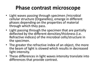
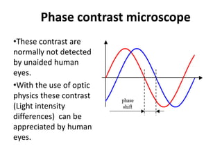
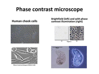
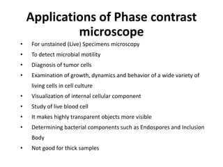
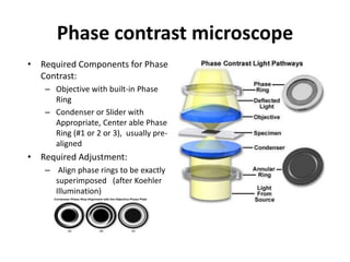
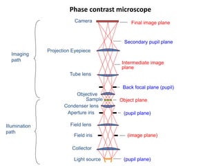
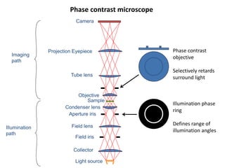
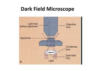
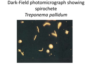
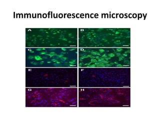
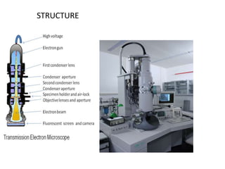
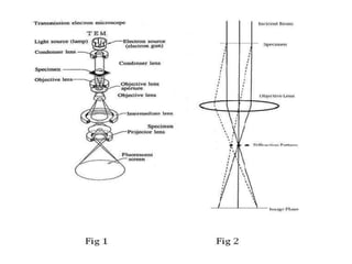
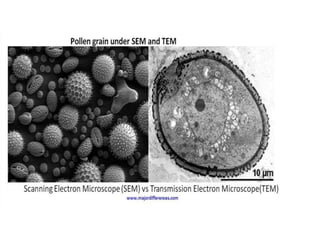
VARIOUS TYPES OF MICROSCOPES
AND MICROSCOPY
Dr. Dinesh Jain
Assistant Professor
Deptt. of Microbiology
SMS MC Jaipur
Phase Contrast Microscope
Phase contrast microscope
• Revolutionary technique for
live cell imaging
• Depends on phase shift 0f
light waves for creating
contrast
• Frits Zernike (Dutch) -Nobel
Prize (1953)
Phase contrast microscope
• Light waves passing through specimen /microbial
cellular structure (Organelles), emerge in different
phases depending on the properties of material
through which they pass.
• Light passing through the specimen that are partially
deflected by the different densities/thickness (i.e.
Refractive indices) of the microbial cells/structure in
the specimen.
• The greater the refractive index of an object, the more
the beam of light is slowed which results in decreased
light intensity.
• These differences in light waves intensity translate into
differences that provide contrast.
Phase contrast microscope
•These contrast are
normally not detected
by unaided human
eyes.
•With the use of optic
physics these contrast
(Light intensity
differences) can be
appreciated by human
eyes.
Phase contrast microscope
• Thus the phase contrast microscope was
developed to improve contrast differences
between the cells and the surrounding
medium, to see living cells without staining
them.
Phase contrast microscope
Human cheek cells
Brightfield (left) and with phase
contrast illumination (right)
• For unstained (Live) Specimens microscopy
• To detect microbial motility
• Diagnosis of tumor cells
• Examination of growth, dynamics and behavior of a wide variety of
living cells in cell culture
• Visualization of internal cellular component
• Study of live blood cell
• It makes highly transparent objects more visible
• Determining bacterial components such as Endospores and Inclusion
Body
• Not good for thick samples
Applications of Phase contrast
microscope
Phase contrast microscope
• Required Components for Phase
Contrast:
– Objective with built-in Phase
Ring
– Condenser or Slider with
Appropriate, Center able Phase
Ring (#1 or 2 or 3), usually pre-
aligned
• Required Adjustment:
– Align phase rings to be exactly
superimposed (after Koehler
Illumination)
Phase contrast microscope
• Need to selectively shift the phase of the
surround wave.
• The sample will scatter light in all directions,
so if we illuminate with a small range of angles
we can specifically alter the phase at those
angles
Phase contrast microscope
Sample
Objective
Tube lens
Projection Eyepiece
Camera
Imaging
path
Aperture iris
Field iris
Intermediate image
plane
Object plane
Back focal plane (pupil)
Secondary pupil plane
Final image plane
(pupil plane)
(image plane)
(pupil plane)Light source
Illumination
path
Collector
Condenser lens
Field lens
Phase contrast microscope
Sample
Objective
Tube lens
Projection Eyepiece
Camera
Imaging
path
Aperture iris
Field iris
Light source
Illumination
path
Collector
Condenser lens
Field lens
Illumination phase
ring
Defines range of
illumination angles
Phase contrast
objective
Selectively retards
surround light
Phase Contrast Microscope
• Negative phase contrast
– Retards surround wave, so objects
which advance phase (low refractive
index) are brighter
• Positive phase contrast
– Advances surround wave, so objects
which retard phase (high refractive
index) are brighter
Limitations of Phase Contrast
• Halos result from diffracted light that is
intercepted by phase ring
• Shade off is caused by greater diffraction at
edges of objects than their centers
Limitations of Phase Contrast
• Poor optical sectioning due
to limited illumination
aperture.
• For sufficiently thick
samples, can get more than
360°phase shift, meaning
thin and thick regions will
be identical in contrast.
Dark Field Microscope
• Dark-field microscopy is similar to phase
contrast microscopy
• It involves the alteration of microscopic
technique rather than the use of dyes or stains
to achieve contrast.
• By the dark-field method, the condenser does
not allow light to pass directly through the
specimen but directs the light to hit the
specimen at an oblique angle
Dark Field Microscope
• Only light that hits objects, such as
microorganisms in the specimen, will be
deflected upward into the objective lens for
visualization.
• All other light that passes through the
specimen will miss the objective, thus making
the background a dark field.
Dark Field Microscope
• Resolution by dark-field microscopy is quite
high.
• Useful for observing Treponema pallidum,
smaller than 0.2 μm in diameter and therefore
cannot be observed with a bright field or
phase contrast microscope.
• Treponema pallidum appear extremely bright
against a black field.
Dark Field Microscope
Application
• For detecting certain bacteria directly in
patient specimens that, because of their thin
dimensions, cannot be seen by light
microscopy and, because of their physiology,
are difficult to grow in culture.
Dark Field Microscope
• Ideal for small
particles, unstained
microorganisms, etc.
• Good Technique for
Live Specimens
• Not so good for large
objects
• Maximizes
detectability
Dark Field Microscope
Dark-Field photomicrograph showing
spirochete
Treponema pallidum
FLUORESCENT MICROSCOPE
PRINCIPLE
• Certain dyes, called fluors or fluorochromes, can be
raised to a higher energy level after absorbing
ultraviolet (excitation) light.
• When the dye molecules return to their normal,
lower energy state, they release excess energy in the
form of visible (fluorescent) light.
• This process is called fluorescence, and microscopic
methods have been developed to exploit the
enhanced contrast and detection that this
phenomenon provides.
FLUORESCENT MICROSCOPE
• Principle of fluorescent microscopy in which the
excitation light is emitted from above
(epifluorescence). An excitation filter passes light of
the desired wavelength to excite the fluorochrome
that has been used to stain the specimen.
• A barrier filter in the objective lens prevents the
excitation wavelengths from damaging the eyes of
the observer.
• When observed through the ocular lens, fluorescing
objects appear brightly lit against a dark background.
FLUORESCENT MICROSCOPE
• The colour of the fluorescent light depends on the dye
and light filters used.
• Use of the fluorescent dyes acridine orange, auramine,
and fluorescein isothiocyanate (FITC) requires blue
excitation light
• Exciter filters that select for light in the 450- to 490-λ
wavelength range and a barrier filter for 515-λ.
• Calcofluor white, on the other hand, requires violet
excitation light, an exciter filter that selects for light in
the 355- to 425-λ wavelength range and a barrier filter
for 460-λ.
FLUORESCENT MICROSCOPE
• Which dye is used often depends on which
organism suspected and the fluorescent method
used.
• The intensity of the contrast obtained with
fluorescent microscopy is an advantage it has
over the use of chromogenic dyes and light
microscopy.
• Some organisms fluoresce naturally because of
the presence within the cells of naturally
fluorescent substances such as chlorophyll.
FLUORESCENT MICROSCOPE
•Fluorescence microscopy is widely used in
clinical diagnostic microbiology.
•Fluorochrome auramine O, which glows yellow
when exposed to ultraviolet light, is strongly
absorbed by Mycobacterium tuberculosis.
•Mycobacterium tuberculosis can be detected
by the appearance of bright yellow organisms
against a dark background.
Mycobacterium tuberculosis
Immunofluorescence
•The principal use of fluorescence microscopy
•Diagnostic technique called the fluorescent-
antibody technique or immunofluorescence.
•Specific antibodies (e.g., antibodies to Legionella
pneumophila) are chemically labeled with a
fluorochrome such as fluorescein isothiocyanate
(FITC).
•These fluorescent antibodies are then added to a
microscope slide containing a clinical specimen.
•The fluorescent antibodies will bind to antigens on the
surface of the bacterium, causing it to fluoresce when
exposed to ultraviolet light.
Immunofluorescence microscopy
LIMITATION OF FLUORESCENT
MICROSCOPE
• Photobleaching - When a fluorophore
permanently loses the ability to fluoresce
due to photon-induced chemical damage
and covalent modification.
ELECTRON MICROSCOPE
• An electron microscope is a microscope that uses a
beam of accelerated electrons as a source of
illumination.
• The wavelength of an electron can be up to 100,000
times shorter than that of visible light photons.
• Electron microscopes have a higher resolving power
than light microscope and can reveal the structure of
smaller objects.
● Parts of EM-
● First condenser lens: The first lens(controlled by "spot size
knob") largely determines the "spot size"; the general size
range of the final spot that strikes the sample.
● Second condenser lens: The second lens(controlled by the
"intensity/ brightness knob" changes the size of the spot on
the sample; changing it from a wide dispersed spot to a
pinpoint beam.
● The other parts include condenser aperture, objective lens,
objective aperture, selected area, Intermediate
lens(magnifies initial image formed by objective lens) &
projector lens
TYPES OF EM
• Transmission Electron Microscope (TEM)
• Scanning Electron Microscope (SEM)
TEM
• Transmission electron microscopy is a microscopy
technique in which a beam of electrons is transmitted
through a specimen to form an image.
STRUCTURE
PRINCIPAL OF TEM
Imaging
● The beam of electrons from the electron gun is focused into a
small, thin, coherent beam by the use of the condenser lens.
● This beam is restricted by the condenser aperture.
● The beam then strikes the specimen and parts of it are transmitted
depending upon the thickness and electron transparency of the
specimen.
● This transmitted portion is focused by the objective lens into an
image on phosphor screen or charge coupled device (CCD) camera.
● The image then passed down the column through the
intermediate and projector lenses, is enlarged all the way.
● The image strikes the phosphor screen and light is
generated, allowing the user to see the image.
● The darker areas of the image represent those areas of the
sample that fewer electrons are transmitted through while
the lighter areas of the image represent those areas of the
sample that more electrons were transmitted through.
Application of TEM
● Application in cancer research, virology, and material
science as well as pollution, nanotechnology and
semiconductor research.
SCANNING ELECTRON MICROSCOPE
• A scanning electron microscope (SEM) is a type of
electron microscope that produces images of a sample
by scanning the surface with a focused beam of
electrons.
• The electrons interact with atoms in the sample, producing
various signals that contain information about the surface
topography and composition of the sample.
Types of signals produced by SEM
● secondary electron
● Back-scattered electrons (BSE)
● X-rays
● Light rays
A standard SEM uses secondary electron and back-scattered
electrons .
WORKING OF SEM
• The beam is constricted by the condenser aperture eliminating some high-
angle electrons
• The second condenser lens forms electrons into a thin, tight, coherent beam
& is controlled by "fine probe current knob“
• The objective aperture further eliminates high-angle electrons from the beam
• A set of coils then "scan" or "sweep" the beam dwelling on points for a period
of time determined by the scan speed (usually in the μs range)
• The Objective lens, focuses the scanning beam onto part of the specimen
desired.
• When the beam strikes the sample (for few μs) interactions occur inside the
sample and are detected by release of electrons.
• The interactions lead to release of – secondary electrons, backscattered
electrons & X- rays.
• These are detected by specialized detectors.
Advantages of SEM
● Better resolution.
● Work with low voltages.
● Fast imaging.
● Easy to operate.
Applications of SEM
● Use in ultra high vacuum, air, water and various liquid
environment.
● Use for the live specimen examination.
● Use for visualization of intracellular change.
● CONFOCAL MICROSCOPE
● SCANNING PROBE MICROSCOPY
● INTERFERENCE MICROSCOPY
● X RAY MICROSCOPY
ADVANCES IN MICROSCOPES
CONFOCAL MICROSCOPE
• Confocal microscopy is an optical imaging technique
for increasing optical resolution and contrast of a
micrograph by means of using a spatiol pinhole to block
out-of-focus light in image formation.
• Capturing multiple two-dimensional images at different
depths in a sample enables the reconstruction of three-
dimensional structure within an object.
Advantages:
• Optical sectioning ability
• 3D reconstruction
• Excellent resolution (0.1-0.2
μm)
• Very high sensitivity
Drawbacks:
• Expensive
• Complex to operate
• Chemical labeling
High intensity laser light
PRINCIPLE OF CONFOCAL
MICROSCOPE
• Confocal microscope uses
fluorescence optics. Instead of
illuminating the whole sample at
once, laser light is focused onto a
defined spot at a specific depth within
the sample. This leads to the
emission of fluorescent light at
exactly this point.
• By scanning many thin sections through a
sample, one can build up a very clean
three-dimensional image .
USES OF CONFOCAL MICROSCOPE
• study of biofilms
• Observing cellular morphology in multilayered
specimen
• Eg. used in diagnosing Ca cervix
• Evaluation and diagnosis of basal cell
carcinoma of skin
SCANNED PROBE MICROSCOPY(SPM)
• SPM was founded in 1981 by Binnig and Rohrer.
• The family of SPM uses no lenses, but rather a probe that
interacts with the sample sureface.
• .Simple design.
• Low cost.
• Easy to handle.
• Automatically resolve image.
Modes of Scanning Probe Microscopy
• The most common modes in SPM are Atomic Force
Microscopy (AFM) and Scanning Tunneling Microscopy
(STM).
How Scanning Probe Microscopy Works
● SPM scans an atomically sharp probe over a surface,
usually at a distance of a few nanometers or angstroms.
The contact between the sharp probe and surface
produces a 3D topographic image of the surface at the
atomic scale.
INTERFERENCE MICROSCOPY
• Interference microscopy is a variation of phase-
contrast microscopy.
• Interference microscopy is an optical microscopy
technique that uses interference between two white-
light illumination beams or rays to generate an image
with enhanced contrast.
• Interference microscopy is superior to phase-contrast
microscopy in its ability to eliminate halos and extra
light.
Three Types-
● classical interference microscopy
● differential contrast interference microscopy
● fluorescence contrast interference microscopy
X-RAY MICROSCOPY
• X-ray microscope invented by Paul Kirkpatrick.
• An X-ray microscope uses electromagnetic radiation in
the soft X-ray band to produce magnified images of
objects.
• Samples are commonly analyzed in a crystal form.
X-ray diffraction analysis workflow.
In an X-ray diffraction
measurement, a crystal is mounted
on a goniometer and gradually
rotated while being bombarded
with X-rays, producing a diffraction
pattern of regularly spaced spots
known as reflections. The two-
dimensional images taken at
different rotations are converted
into a three-dimensional model of
the density of electrons within the
crystal .
Thank You

Various types of microscopes and microscopy

  • 1.
    VARIOUS TYPES OFMICROSCOPES AND MICROSCOPY Dr. Dinesh Jain Assistant Professor Deptt. of Microbiology SMS MC Jaipur
  • 2.
  • 3.
    Phase contrast microscope •Revolutionary technique for live cell imaging • Depends on phase shift 0f light waves for creating contrast • Frits Zernike (Dutch) -Nobel Prize (1953)
  • 4.
    Phase contrast microscope •Light waves passing through specimen /microbial cellular structure (Organelles), emerge in different phases depending on the properties of material through which they pass. • Light passing through the specimen that are partially deflected by the different densities/thickness (i.e. Refractive indices) of the microbial cells/structure in the specimen. • The greater the refractive index of an object, the more the beam of light is slowed which results in decreased light intensity. • These differences in light waves intensity translate into differences that provide contrast.
  • 5.
    Phase contrast microscope •Thesecontrast are normally not detected by unaided human eyes. •With the use of optic physics these contrast (Light intensity differences) can be appreciated by human eyes.
  • 6.
    Phase contrast microscope •Thus the phase contrast microscope was developed to improve contrast differences between the cells and the surrounding medium, to see living cells without staining them.
  • 7.
    Phase contrast microscope Humancheek cells Brightfield (left) and with phase contrast illumination (right)
  • 8.
    • For unstained(Live) Specimens microscopy • To detect microbial motility • Diagnosis of tumor cells • Examination of growth, dynamics and behavior of a wide variety of living cells in cell culture • Visualization of internal cellular component • Study of live blood cell • It makes highly transparent objects more visible • Determining bacterial components such as Endospores and Inclusion Body • Not good for thick samples Applications of Phase contrast microscope
  • 9.
    Phase contrast microscope •Required Components for Phase Contrast: – Objective with built-in Phase Ring – Condenser or Slider with Appropriate, Center able Phase Ring (#1 or 2 or 3), usually pre- aligned • Required Adjustment: – Align phase rings to be exactly superimposed (after Koehler Illumination)
  • 10.
    Phase contrast microscope •Need to selectively shift the phase of the surround wave. • The sample will scatter light in all directions, so if we illuminate with a small range of angles we can specifically alter the phase at those angles
  • 11.
    Phase contrast microscope Sample Objective Tubelens Projection Eyepiece Camera Imaging path Aperture iris Field iris Intermediate image plane Object plane Back focal plane (pupil) Secondary pupil plane Final image plane (pupil plane) (image plane) (pupil plane)Light source Illumination path Collector Condenser lens Field lens
  • 12.
    Phase contrast microscope Sample Objective Tubelens Projection Eyepiece Camera Imaging path Aperture iris Field iris Light source Illumination path Collector Condenser lens Field lens Illumination phase ring Defines range of illumination angles Phase contrast objective Selectively retards surround light
  • 13.
    Phase Contrast Microscope •Negative phase contrast – Retards surround wave, so objects which advance phase (low refractive index) are brighter • Positive phase contrast – Advances surround wave, so objects which retard phase (high refractive index) are brighter
  • 14.
    Limitations of PhaseContrast • Halos result from diffracted light that is intercepted by phase ring • Shade off is caused by greater diffraction at edges of objects than their centers
  • 15.
    Limitations of PhaseContrast • Poor optical sectioning due to limited illumination aperture. • For sufficiently thick samples, can get more than 360°phase shift, meaning thin and thick regions will be identical in contrast.
  • 16.
  • 17.
    Dark Field Microscope •Dark-field microscopy is similar to phase contrast microscopy • It involves the alteration of microscopic technique rather than the use of dyes or stains to achieve contrast. • By the dark-field method, the condenser does not allow light to pass directly through the specimen but directs the light to hit the specimen at an oblique angle
  • 18.
    Dark Field Microscope •Only light that hits objects, such as microorganisms in the specimen, will be deflected upward into the objective lens for visualization. • All other light that passes through the specimen will miss the objective, thus making the background a dark field.
  • 19.
    Dark Field Microscope •Resolution by dark-field microscopy is quite high. • Useful for observing Treponema pallidum, smaller than 0.2 μm in diameter and therefore cannot be observed with a bright field or phase contrast microscope. • Treponema pallidum appear extremely bright against a black field.
  • 20.
    Dark Field Microscope Application •For detecting certain bacteria directly in patient specimens that, because of their thin dimensions, cannot be seen by light microscopy and, because of their physiology, are difficult to grow in culture.
  • 21.
    Dark Field Microscope •Ideal for small particles, unstained microorganisms, etc. • Good Technique for Live Specimens • Not so good for large objects • Maximizes detectability
  • 22.
  • 23.
  • 24.
    FLUORESCENT MICROSCOPE PRINCIPLE • Certaindyes, called fluors or fluorochromes, can be raised to a higher energy level after absorbing ultraviolet (excitation) light. • When the dye molecules return to their normal, lower energy state, they release excess energy in the form of visible (fluorescent) light. • This process is called fluorescence, and microscopic methods have been developed to exploit the enhanced contrast and detection that this phenomenon provides.
  • 25.
  • 26.
    FLUORESCENT MICROSCOPE • Principleof fluorescent microscopy in which the excitation light is emitted from above (epifluorescence). An excitation filter passes light of the desired wavelength to excite the fluorochrome that has been used to stain the specimen. • A barrier filter in the objective lens prevents the excitation wavelengths from damaging the eyes of the observer. • When observed through the ocular lens, fluorescing objects appear brightly lit against a dark background.
  • 27.
  • 28.
    FLUORESCENT MICROSCOPE • Thecolour of the fluorescent light depends on the dye and light filters used. • Use of the fluorescent dyes acridine orange, auramine, and fluorescein isothiocyanate (FITC) requires blue excitation light • Exciter filters that select for light in the 450- to 490-λ wavelength range and a barrier filter for 515-λ. • Calcofluor white, on the other hand, requires violet excitation light, an exciter filter that selects for light in the 355- to 425-λ wavelength range and a barrier filter for 460-λ.
  • 29.
    FLUORESCENT MICROSCOPE • Whichdye is used often depends on which organism suspected and the fluorescent method used. • The intensity of the contrast obtained with fluorescent microscopy is an advantage it has over the use of chromogenic dyes and light microscopy. • Some organisms fluoresce naturally because of the presence within the cells of naturally fluorescent substances such as chlorophyll.
  • 30.
    FLUORESCENT MICROSCOPE •Fluorescence microscopyis widely used in clinical diagnostic microbiology. •Fluorochrome auramine O, which glows yellow when exposed to ultraviolet light, is strongly absorbed by Mycobacterium tuberculosis. •Mycobacterium tuberculosis can be detected by the appearance of bright yellow organisms against a dark background.
  • 31.
  • 32.
    Immunofluorescence •The principal useof fluorescence microscopy •Diagnostic technique called the fluorescent- antibody technique or immunofluorescence. •Specific antibodies (e.g., antibodies to Legionella pneumophila) are chemically labeled with a fluorochrome such as fluorescein isothiocyanate (FITC). •These fluorescent antibodies are then added to a microscope slide containing a clinical specimen. •The fluorescent antibodies will bind to antigens on the surface of the bacterium, causing it to fluoresce when exposed to ultraviolet light.
  • 33.
  • 34.
    LIMITATION OF FLUORESCENT MICROSCOPE •Photobleaching - When a fluorophore permanently loses the ability to fluoresce due to photon-induced chemical damage and covalent modification.
  • 35.
    ELECTRON MICROSCOPE • Anelectron microscope is a microscope that uses a beam of accelerated electrons as a source of illumination. • The wavelength of an electron can be up to 100,000 times shorter than that of visible light photons. • Electron microscopes have a higher resolving power than light microscope and can reveal the structure of smaller objects.
  • 36.
    ● Parts ofEM- ● First condenser lens: The first lens(controlled by "spot size knob") largely determines the "spot size"; the general size range of the final spot that strikes the sample. ● Second condenser lens: The second lens(controlled by the "intensity/ brightness knob" changes the size of the spot on the sample; changing it from a wide dispersed spot to a pinpoint beam. ● The other parts include condenser aperture, objective lens, objective aperture, selected area, Intermediate lens(magnifies initial image formed by objective lens) & projector lens
  • 37.
    TYPES OF EM •Transmission Electron Microscope (TEM) • Scanning Electron Microscope (SEM)
  • 38.
    TEM • Transmission electronmicroscopy is a microscopy technique in which a beam of electrons is transmitted through a specimen to form an image.
  • 39.
  • 40.
  • 42.
    Imaging ● The beamof electrons from the electron gun is focused into a small, thin, coherent beam by the use of the condenser lens. ● This beam is restricted by the condenser aperture. ● The beam then strikes the specimen and parts of it are transmitted depending upon the thickness and electron transparency of the specimen. ● This transmitted portion is focused by the objective lens into an image on phosphor screen or charge coupled device (CCD) camera. ● The image then passed down the column through the intermediate and projector lenses, is enlarged all the way.
  • 43.
    ● The imagestrikes the phosphor screen and light is generated, allowing the user to see the image. ● The darker areas of the image represent those areas of the sample that fewer electrons are transmitted through while the lighter areas of the image represent those areas of the sample that more electrons were transmitted through.
  • 45.
    Application of TEM ●Application in cancer research, virology, and material science as well as pollution, nanotechnology and semiconductor research.
  • 46.
    SCANNING ELECTRON MICROSCOPE •A scanning electron microscope (SEM) is a type of electron microscope that produces images of a sample by scanning the surface with a focused beam of electrons. • The electrons interact with atoms in the sample, producing various signals that contain information about the surface topography and composition of the sample.
  • 47.
    Types of signalsproduced by SEM ● secondary electron ● Back-scattered electrons (BSE) ● X-rays ● Light rays A standard SEM uses secondary electron and back-scattered electrons .
  • 48.
  • 49.
    • The beamis constricted by the condenser aperture eliminating some high- angle electrons • The second condenser lens forms electrons into a thin, tight, coherent beam & is controlled by "fine probe current knob“ • The objective aperture further eliminates high-angle electrons from the beam • A set of coils then "scan" or "sweep" the beam dwelling on points for a period of time determined by the scan speed (usually in the μs range) • The Objective lens, focuses the scanning beam onto part of the specimen desired. • When the beam strikes the sample (for few μs) interactions occur inside the sample and are detected by release of electrons. • The interactions lead to release of – secondary electrons, backscattered electrons & X- rays. • These are detected by specialized detectors.
  • 50.
    Advantages of SEM ●Better resolution. ● Work with low voltages. ● Fast imaging. ● Easy to operate.
  • 51.
    Applications of SEM ●Use in ultra high vacuum, air, water and various liquid environment. ● Use for the live specimen examination. ● Use for visualization of intracellular change.
  • 54.
    ● CONFOCAL MICROSCOPE ●SCANNING PROBE MICROSCOPY ● INTERFERENCE MICROSCOPY ● X RAY MICROSCOPY ADVANCES IN MICROSCOPES
  • 55.
    CONFOCAL MICROSCOPE • Confocalmicroscopy is an optical imaging technique for increasing optical resolution and contrast of a micrograph by means of using a spatiol pinhole to block out-of-focus light in image formation. • Capturing multiple two-dimensional images at different depths in a sample enables the reconstruction of three- dimensional structure within an object.
  • 56.
    Advantages: • Optical sectioningability • 3D reconstruction • Excellent resolution (0.1-0.2 μm) • Very high sensitivity Drawbacks: • Expensive • Complex to operate • Chemical labeling High intensity laser light
  • 57.
    PRINCIPLE OF CONFOCAL MICROSCOPE •Confocal microscope uses fluorescence optics. Instead of illuminating the whole sample at once, laser light is focused onto a defined spot at a specific depth within the sample. This leads to the emission of fluorescent light at exactly this point. • By scanning many thin sections through a sample, one can build up a very clean three-dimensional image .
  • 58.
    USES OF CONFOCALMICROSCOPE • study of biofilms • Observing cellular morphology in multilayered specimen • Eg. used in diagnosing Ca cervix • Evaluation and diagnosis of basal cell carcinoma of skin
  • 59.
    SCANNED PROBE MICROSCOPY(SPM) •SPM was founded in 1981 by Binnig and Rohrer. • The family of SPM uses no lenses, but rather a probe that interacts with the sample sureface. • .Simple design. • Low cost. • Easy to handle. • Automatically resolve image.
  • 60.
    Modes of ScanningProbe Microscopy • The most common modes in SPM are Atomic Force Microscopy (AFM) and Scanning Tunneling Microscopy (STM).
  • 61.
    How Scanning ProbeMicroscopy Works ● SPM scans an atomically sharp probe over a surface, usually at a distance of a few nanometers or angstroms. The contact between the sharp probe and surface produces a 3D topographic image of the surface at the atomic scale.
  • 62.
    INTERFERENCE MICROSCOPY • Interferencemicroscopy is a variation of phase- contrast microscopy. • Interference microscopy is an optical microscopy technique that uses interference between two white- light illumination beams or rays to generate an image with enhanced contrast. • Interference microscopy is superior to phase-contrast microscopy in its ability to eliminate halos and extra light.
  • 63.
    Three Types- ● classicalinterference microscopy ● differential contrast interference microscopy ● fluorescence contrast interference microscopy
  • 64.
    X-RAY MICROSCOPY • X-raymicroscope invented by Paul Kirkpatrick. • An X-ray microscope uses electromagnetic radiation in the soft X-ray band to produce magnified images of objects. • Samples are commonly analyzed in a crystal form.
  • 65.
    X-ray diffraction analysisworkflow. In an X-ray diffraction measurement, a crystal is mounted on a goniometer and gradually rotated while being bombarded with X-rays, producing a diffraction pattern of regularly spaced spots known as reflections. The two- dimensional images taken at different rotations are converted into a three-dimensional model of the density of electrons within the crystal .
  • 66.