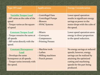
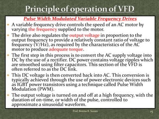
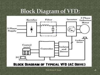
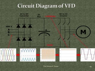
INTRODUCTION
TO
VARIABLE FREQUENCY
DRIVES
Prof. Rozina R. Surani
Asst. Prof.
Electrical Engineering Department
VGEC-Chandkheda
1
INTRODUCTION
 A Variable-Frequency Drive (VFD) is a device that controls the
voltage and frequency that is being supplied to AC motor and
therefore controls the speed of the motor and the system it is
driving. By meeting the required process demands, the system
efficiency is improved.
 A VFD is capable of adjusting both the speed and torque of an
induction motor.
 A VFD therefore provides continuous range process speed
control (as compared to the discrete speed control that
gearboxes or multi-speed motors provide).
 VFDs may be referred to by a variety of other names, such as
variable speed drives, adjustable speed drives, or inverters.
2Prof. Rozina R. Surani
Why VFD/Adjustable speed drives?
 Energy Savings: Centrifugal fan and pump loads operated with an
Adjustable Speed AC Drive reduces energy consumption.
 Centrifugal fans and pumps follow a variable torque load profile,
which has horsepower proportional to the cube of speed and torque
varying proportional to the square of speed. As such, if the speed of
the fan is cut in half, the horsepower needed to run the fan at load is
cut by a factor of eight (1/2)3 =1/8.
 Improve power factor: As the motor load is reduced, the power
factor becomes low. The advantage of using VFD’s is that it includes
capacitors in the DC Bus itself which maintains high power factor on
the line side of the Variable Frequency Drive. This eliminates the
need of additional expensive capacitor banks.
3Prof. Rozina R. Surani
 Controlled Starting Current: When an AC motor is
started "across the line," it takes as much as seven-to-eight
times the motor full-load current to start the motor and
load. The customer payback is less wear and tear on the
motor (motor rewinds), and extended motor life.
 Reduced Power Line Disturbances: Using an
Adjustable Speed AC Drive eliminates this voltage sag,
since the motor is started at zero voltage and ramped up.
 Soft Starting: When Variable Frequency Drives start
large motors, the drawbacks associated with large inrush
current i.e. starting current (winding stress, winding
overheating and voltage dip on connected bus) is
eliminated. This reduces chances of insulation or winding
damage and provides extended motor life.
4Prof. Rozina R. Surani
Prof. Rozina R. Surani 5
 Adjustable Operating Speed:
 Adjustable Torque Limit:
 Controlled Stopping -- Just as important as controlled acceleration,
controlled stopping can be important to reduce mechanical wear and
tear
 Reverse Operation -- Using an Adjustable Speed AC Drive
eliminates the need for a reversing starter, since the output phases to
the motor can be electronically changed without any mechanical
devices. The elimination of a reversing starter eliminates its
maintenance cost and reduces panel space.
 Elimination of Mechanical Drive Components -- Using an
Adjustable Speed AC Drive can eliminate the need for expensive
mechanical drive components such as gearboxes. Because the AC
Drive can operate with an infinite variable speed, it can deliver the
low- or high-speed required by the load, without a speed-increasing or
reduction devices between the motor and load. This eliminates
maintenance costs, as well as reducing floor-space requirements.
Type Of Load Applications Energy Consideration
Variable Torque Load
- HP varies as the cube of the
speed
- Torque varies as the square
of speed
- Centrifugal Fans
- Centrifugal Pumps
- Blowers
- HVAC Systems
Lower speed operation
results in significant energy
savings as power to the
motor drops with the cube of
the speed.
Constant Torque Load
- Torque remains the same at
all speeds
- HP varies directly with the
speed.
- Mixers
- Conveyors
- Compressors
- Printing Presses
Lower speed operation saves
energy in direct proportion
to the speed reduction.
Constant Horsepower
Load
- Develops the same
horsepower at all speeds.
- Torque varies inversely with
the speed.
- Machine tools
- Lathes
- Milling machines
- Punch presses
No energy savings at reduced
speeds; however, energy
savings can be realized by
attaining the optimized
cutting and machining
speeds for the part being
produced.
6Prof. Rozina R. Surani
DC Drives
 Direct current (DC) motors are inherently variable
speed machines. Speed and torque control is achieved
by varying the armature voltage, the field excitation, or
both.
 Traditionally, speed control for a DC motor came from
a motor-generator, or M-G set. In an M-G set, an AC
motor drives a DC generator to provide variable voltage
DC for motor operation. M-G sets are large, inefficient
and require a lot of maintenance.
 M-G sets have now been replaced with microprocessor
controlled rectifier sets, which permit simple and
accurate speed control, high efficiency and reliability.
7Prof. Rozina R. Surani
 However, due to the complexity, cost and maintenance
associated with a DC motor, they are seldom used in
new applications. Many existing DC drive applications
are being replaced with AC motors and VFDs.
 New applications using DC motors and drives are
usually engineered applications where AC motors and
drives cannot fulfil a load requirement.
 An example is for traction drives where the starting
torque requirements exceed that available from AC
motors.
8Prof. Rozina R. Surani
 An AC induction motor is constructed with a rotor that has windings which
intersect the rotating magnetic field generated by the stator windings.
 At full load speed, the rotor turns slightly slower than the synchronous
speed of the motor. This is because the magnetic field causes currents to
flow in the rotor windings and produces a torque which turns the rotor; so if
the rotor turns at the same speed as the magnetic field, there would be no
relative motion between the rotor and the magnetic field, and no torque
would be produced.
 The amount of speed by which the rotor lags the rotating magnetic field is
known as the slip of the motor. The higher the slip, the more torque is
produced by the motor.
 The speed at which the magnetic field rotates depends on the number of
poles or coils distributed around the stator and the frequency of the supply
current. This is called the synchronous speed.
 Synchronous Speed = 120 x Frequency /No. of Poles
 Typical AC induction motor speeds are 3600, 1800, 1200, and 900 RPM.
9Prof. Rozina R. Surani
10Prof. Rozina R. Surani
 Synchronous Speed Ns=120f/P
Where, f = frequency and P is the number of poles
The speed of induction motor, N=Ns(1-S)
Where, N is the speed of rotor,
Ns is the synchronous speed,
S is the slip. At standstill slip is one.
The torque produced by three phase induction motor is given
by,
E2 is the rotor emf
3/2πNs is,K=constant
Ns is the synchronous speed
R2 is the rotor resistance
X2 is the rotor inductive reactance
11Prof. Rozina R. Surani
The speed control of three phase induction motor from
stator side are classified as :
 V / f control or frequency control.
 Changing the number of stator poles.
 Controlling supply voltage.
 Adding rheostat in the stator circuit.
 The speed controls of three phase induction motor
from rotor side are further classified as:
 Adding external resistance on rotor side.
 Cascade control method.
 Injecting slip frequency emf into rotor side.
12Prof. Rozina R. Surani
V / f control or frequency control
we know, Ns=120f/P
And
By changing f , speed can change but decrease in f will increase
flux causes saturation of core, increase no load current.
So, its important to maintain flux , φ constant and it is only
possible if we change voltage, i.e if we decrease frequency,
flux increases but at the same time if we decrease voltage , flux
will also decease causing no change in flux and hence it
remains constant.
So, here we are keeping the ratio of V/f as constant. Hence its
name is V/ f method.
For controlling the speed of three phase induction motor by V/f
method we have variable supply voltage and frequency which
is easily obtained by using converter and inverter set.
13Prof. Rozina R. Surani
 Controlling supply voltage: The torque produced by
running three phase induction motor is given by,
 T α sE22R2/{(R22+(SX2)2}
 In low slip region (SX)2 is very small as
compared to R2. So, it can be neglected. So
torque becomes---T= sE22 / R2
 Since rotor resistance, R2 is constant so the equation of
torque further reduces to sE22
i.e. T α SV2
 This method of speed control is rarely used because small
change in speed requires large reduction in voltage, and
hence the current drawn by motor increases, which cause
over heating of induction motor
14Prof. Rozina R. Surani
Pulse Width Modulated Variable Frequency Drives
 A variable frequency drive controls the speed of an AC motor by
varying the frequency supplied to the motor.
 The drive also regulates the output voltage in proportion to the
output frequency to provide a relatively constant ratio of voltage to
frequency (V/Hz), as required by the characteristics of the AC
motor to produce adequate torque.
 The first step in this process is to convert the AC supply voltage into
DC by the use of a rectifier. DC power contains voltage ripples which
are smoothed using filter capacitors. This section of the VFD is
often referred to as the DC link.
 This DC voltage is then converted back into AC. This conversion is
typically achieved through the use of power electronic devices such
as IGBT power transistors using a technique called Pulse Width
Modulation (PWM).
 The output voltage is turned on and off at a high frequency, with the
duration of on-time, or width of the pulse, controlled to
approximate a sinusoidal waveform.
15Prof. Rozina R. Surani
The entire process is controlled by a microprocessor
which monitors the:
 incoming voltage supply,
 speed set-point,
 DC link voltage,
 output voltage and current to ensure operation of the
motor within established parameters.
16Prof. Rozina R. Surani
Railway lectureanimation How a VFD or variable
frequency drive works.mp4
ABB ACQ810 - The water industry specific drive.mp4
17Prof. Rozina R. Surani
18Prof. Rozina R. Surani
19Prof. Rozina R. Surani
20Prof. Rozina R. Surani

Introduction to vfd

  • 1.
    INTRODUCTION TO VARIABLE FREQUENCY DRIVES Prof. RozinaR. Surani Asst. Prof. Electrical Engineering Department VGEC-Chandkheda 1
  • 2.
    INTRODUCTION  A Variable-FrequencyDrive (VFD) is a device that controls the voltage and frequency that is being supplied to AC motor and therefore controls the speed of the motor and the system it is driving. By meeting the required process demands, the system efficiency is improved.  A VFD is capable of adjusting both the speed and torque of an induction motor.  A VFD therefore provides continuous range process speed control (as compared to the discrete speed control that gearboxes or multi-speed motors provide).  VFDs may be referred to by a variety of other names, such as variable speed drives, adjustable speed drives, or inverters. 2Prof. Rozina R. Surani
  • 3.
    Why VFD/Adjustable speeddrives?  Energy Savings: Centrifugal fan and pump loads operated with an Adjustable Speed AC Drive reduces energy consumption.  Centrifugal fans and pumps follow a variable torque load profile, which has horsepower proportional to the cube of speed and torque varying proportional to the square of speed. As such, if the speed of the fan is cut in half, the horsepower needed to run the fan at load is cut by a factor of eight (1/2)3 =1/8.  Improve power factor: As the motor load is reduced, the power factor becomes low. The advantage of using VFD’s is that it includes capacitors in the DC Bus itself which maintains high power factor on the line side of the Variable Frequency Drive. This eliminates the need of additional expensive capacitor banks. 3Prof. Rozina R. Surani
  • 4.
     Controlled StartingCurrent: When an AC motor is started "across the line," it takes as much as seven-to-eight times the motor full-load current to start the motor and load. The customer payback is less wear and tear on the motor (motor rewinds), and extended motor life.  Reduced Power Line Disturbances: Using an Adjustable Speed AC Drive eliminates this voltage sag, since the motor is started at zero voltage and ramped up.  Soft Starting: When Variable Frequency Drives start large motors, the drawbacks associated with large inrush current i.e. starting current (winding stress, winding overheating and voltage dip on connected bus) is eliminated. This reduces chances of insulation or winding damage and provides extended motor life. 4Prof. Rozina R. Surani
  • 5.
    Prof. Rozina R.Surani 5  Adjustable Operating Speed:  Adjustable Torque Limit:  Controlled Stopping -- Just as important as controlled acceleration, controlled stopping can be important to reduce mechanical wear and tear  Reverse Operation -- Using an Adjustable Speed AC Drive eliminates the need for a reversing starter, since the output phases to the motor can be electronically changed without any mechanical devices. The elimination of a reversing starter eliminates its maintenance cost and reduces panel space.  Elimination of Mechanical Drive Components -- Using an Adjustable Speed AC Drive can eliminate the need for expensive mechanical drive components such as gearboxes. Because the AC Drive can operate with an infinite variable speed, it can deliver the low- or high-speed required by the load, without a speed-increasing or reduction devices between the motor and load. This eliminates maintenance costs, as well as reducing floor-space requirements.
  • 6.
    Type Of LoadApplications Energy Consideration Variable Torque Load - HP varies as the cube of the speed - Torque varies as the square of speed - Centrifugal Fans - Centrifugal Pumps - Blowers - HVAC Systems Lower speed operation results in significant energy savings as power to the motor drops with the cube of the speed. Constant Torque Load - Torque remains the same at all speeds - HP varies directly with the speed. - Mixers - Conveyors - Compressors - Printing Presses Lower speed operation saves energy in direct proportion to the speed reduction. Constant Horsepower Load - Develops the same horsepower at all speeds. - Torque varies inversely with the speed. - Machine tools - Lathes - Milling machines - Punch presses No energy savings at reduced speeds; however, energy savings can be realized by attaining the optimized cutting and machining speeds for the part being produced. 6Prof. Rozina R. Surani
  • 7.
    DC Drives  Directcurrent (DC) motors are inherently variable speed machines. Speed and torque control is achieved by varying the armature voltage, the field excitation, or both.  Traditionally, speed control for a DC motor came from a motor-generator, or M-G set. In an M-G set, an AC motor drives a DC generator to provide variable voltage DC for motor operation. M-G sets are large, inefficient and require a lot of maintenance.  M-G sets have now been replaced with microprocessor controlled rectifier sets, which permit simple and accurate speed control, high efficiency and reliability. 7Prof. Rozina R. Surani
  • 8.
     However, dueto the complexity, cost and maintenance associated with a DC motor, they are seldom used in new applications. Many existing DC drive applications are being replaced with AC motors and VFDs.  New applications using DC motors and drives are usually engineered applications where AC motors and drives cannot fulfil a load requirement.  An example is for traction drives where the starting torque requirements exceed that available from AC motors. 8Prof. Rozina R. Surani
  • 9.
     An ACinduction motor is constructed with a rotor that has windings which intersect the rotating magnetic field generated by the stator windings.  At full load speed, the rotor turns slightly slower than the synchronous speed of the motor. This is because the magnetic field causes currents to flow in the rotor windings and produces a torque which turns the rotor; so if the rotor turns at the same speed as the magnetic field, there would be no relative motion between the rotor and the magnetic field, and no torque would be produced.  The amount of speed by which the rotor lags the rotating magnetic field is known as the slip of the motor. The higher the slip, the more torque is produced by the motor.  The speed at which the magnetic field rotates depends on the number of poles or coils distributed around the stator and the frequency of the supply current. This is called the synchronous speed.  Synchronous Speed = 120 x Frequency /No. of Poles  Typical AC induction motor speeds are 3600, 1800, 1200, and 900 RPM. 9Prof. Rozina R. Surani
  • 10.
  • 11.
     Synchronous SpeedNs=120f/P Where, f = frequency and P is the number of poles The speed of induction motor, N=Ns(1-S) Where, N is the speed of rotor, Ns is the synchronous speed, S is the slip. At standstill slip is one. The torque produced by three phase induction motor is given by, E2 is the rotor emf 3/2πNs is,K=constant Ns is the synchronous speed R2 is the rotor resistance X2 is the rotor inductive reactance 11Prof. Rozina R. Surani
  • 12.
    The speed controlof three phase induction motor from stator side are classified as :  V / f control or frequency control.  Changing the number of stator poles.  Controlling supply voltage.  Adding rheostat in the stator circuit.  The speed controls of three phase induction motor from rotor side are further classified as:  Adding external resistance on rotor side.  Cascade control method.  Injecting slip frequency emf into rotor side. 12Prof. Rozina R. Surani
  • 13.
    V / fcontrol or frequency control we know, Ns=120f/P And By changing f , speed can change but decrease in f will increase flux causes saturation of core, increase no load current. So, its important to maintain flux , φ constant and it is only possible if we change voltage, i.e if we decrease frequency, flux increases but at the same time if we decrease voltage , flux will also decease causing no change in flux and hence it remains constant. So, here we are keeping the ratio of V/f as constant. Hence its name is V/ f method. For controlling the speed of three phase induction motor by V/f method we have variable supply voltage and frequency which is easily obtained by using converter and inverter set. 13Prof. Rozina R. Surani
  • 14.
     Controlling supplyvoltage: The torque produced by running three phase induction motor is given by,  T α sE22R2/{(R22+(SX2)2}  In low slip region (SX)2 is very small as compared to R2. So, it can be neglected. So torque becomes---T= sE22 / R2  Since rotor resistance, R2 is constant so the equation of torque further reduces to sE22 i.e. T α SV2  This method of speed control is rarely used because small change in speed requires large reduction in voltage, and hence the current drawn by motor increases, which cause over heating of induction motor 14Prof. Rozina R. Surani
  • 15.
    Pulse Width ModulatedVariable Frequency Drives  A variable frequency drive controls the speed of an AC motor by varying the frequency supplied to the motor.  The drive also regulates the output voltage in proportion to the output frequency to provide a relatively constant ratio of voltage to frequency (V/Hz), as required by the characteristics of the AC motor to produce adequate torque.  The first step in this process is to convert the AC supply voltage into DC by the use of a rectifier. DC power contains voltage ripples which are smoothed using filter capacitors. This section of the VFD is often referred to as the DC link.  This DC voltage is then converted back into AC. This conversion is typically achieved through the use of power electronic devices such as IGBT power transistors using a technique called Pulse Width Modulation (PWM).  The output voltage is turned on and off at a high frequency, with the duration of on-time, or width of the pulse, controlled to approximate a sinusoidal waveform. 15Prof. Rozina R. Surani
  • 16.
    The entire processis controlled by a microprocessor which monitors the:  incoming voltage supply,  speed set-point,  DC link voltage,  output voltage and current to ensure operation of the motor within established parameters. 16Prof. Rozina R. Surani
  • 17.
    Railway lectureanimation Howa VFD or variable frequency drive works.mp4 ABB ACQ810 - The water industry specific drive.mp4 17Prof. Rozina R. Surani
  • 18.
  • 19.
  • 20.