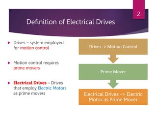
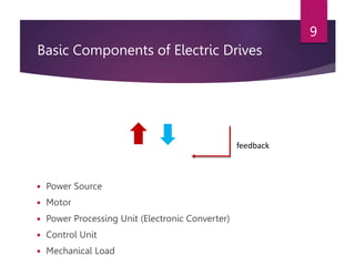
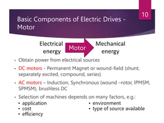
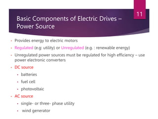
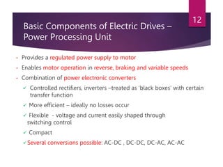
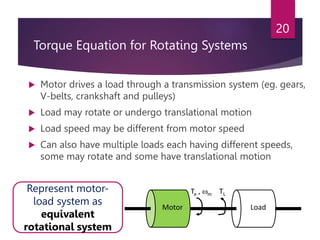
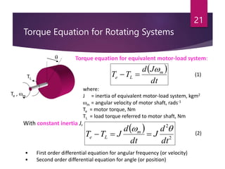
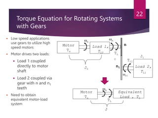
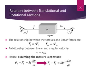
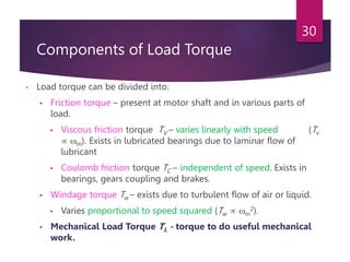
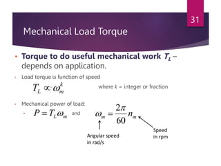
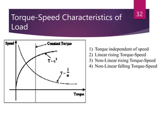
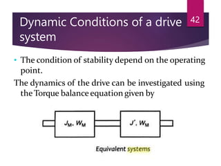
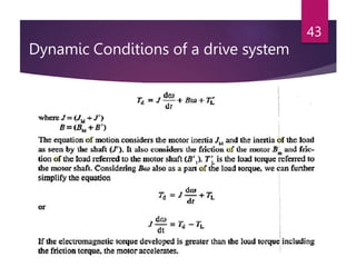
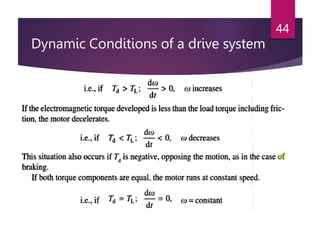
CHAPTER 1:
ELECTRICAL DRIVES
By
Mr. Harshal Vaidya
Assistant Professor
Department of Electrical Engineering
DIT, Pune
Definition of Electrical Drives
 Drives – system employed
for motion control
 Motion control requires
prime movers
 Electrical Drives – Drives
that employ Electric Motors
as prime movers Electrical Drives -> Electric
Motor as Prime Mover
Prime Mover
Drives -> Motion Control
2
Advantages of Electrical Drives
 Flexible control characteristic
 particularly when power electronic converters are employed
 Wide range of speed, torque and power
 High efficiency – low no load losses
 Low noise
 Low maintenance requirements, cleaner operation
 Electric energy easily transported
 Adaptable to most operating conditions
 Available operation in all four torque-speed quadrants
3
Conventional Electric Drives
 Ward-Leonard system –
introduced in 1890s
 Disadvantage :
 Bulky
 Expensive
 Inefficient
 Complex
4
Modern Electric Drives
 Small (compact)
 Efficient
 Flexible
 Interdisciplinary
5
feedback
Electric Drives Application
 Line Shaft Drives
 Oldest form
 Single motor,
multiple loads
 Common line
shaft or belt
 Inflexible
 Inefficient
 Rarely used
6
Electric Drives Application
 Single-Motor, Single-
Load Drives
 Most common
 Eg: electric saws, drills,
fans, washers, blenders,
disk-drives, electric cars.
7
Electric Drives Application
 Multi-motor
Drives
 Several motors,
single
mechanical
load
 Complex drive
functions
 Eg: assembly
lines, robotics,
military
airplane
actuation.
8
Basic Components of Electric Drives
 Power Source
 Motor
 Power Processing Unit (Electronic Converter)
 Control Unit
 Mechanical Load
9
feedback
Basic Components of Electric Drives -
Motor
• Obtain power from electrical sources
• DC motors - Permanent Magnet or wound-field (shunt,
separately excited, compound, series)
• AC motors – Induction, Synchronous (wound –rotor, IPMSM,
SPMSM), brushless DC
• Selection of machines depends on many factors, e.g.:
10
Electrical
energy
Mechanical
energy
Motor
• application
• cost
• efficiency
• environment
• type of source available
Basic Components of Electric Drives –
Power Source
• Provides energy to electric motors
• Regulated (e.g: utility) or Unregulated (e.g. : renewable energy)
• Unregulated power sources must be regulated for high efficiency – use
power electronic converters
• DC source
• batteries
• fuel cell
• photovoltaic
• AC source
• single- or three- phase utility
• wind generator
11
Basic Components of Electric Drives –
Power Processing Unit
• Provides a regulated power supply to motor
• Enables motor operation in reverse, braking and variable speeds
• Combination of power electronic converters
 Controlled rectifiers, inverters –treated as ‘black boxes’ with certain
transfer function
 More efficient – ideally no losses occur
 Flexible - voltage and current easily shaped through
switching control
 Compact
Several conversions possible: AC-DC , DC-DC, DC-AC, AC-AC
12
Basic Components of Electric Drives –
Power Processing Unit
 DC to AC:
13
Basic Components of Electric Drives –
Power Processing Unit
 DC to DC:
14
Basic Components of Electric Drives –
Power Processing Unit
 AC to DC:
15
Basic Components of Electric Drives –
Power Processing Unit
 AC to AC:
16
Basic Components of Electric Drives –
Control Unit
• Supervise operation
• Enhance overall performance and stability
• Complexity depends on performance requirement
• Analog Control – noisy, inflexible, ideally infinite bandwidth
• Digital Control – immune to noise, configurable, smaller
bandwidth (depends on sampling frequency)
• DSP/microprocessor – flexible, lower bandwidth, real-time
• DSPs perform faster operation than microprocessors
(multiplication in single cycle), complex estimations and
observers easily implemented
17
Basic Components of Electric Drives
– Component Selection
• Several factors affecting drive selection:
• Steady-state operation requirements
• nature of torque-speed profile, speed regulation, speed range, efficiency,
quadrants of operations, converter ratings
• Transient operation requirements
• values of acceleration and deceleration, starting, braking and reversing
performance
• Power source requirements
• Type, capacity, voltage magnitude, voltage fluctuations, power factor, harmonics
and its effect on loads, ability to accept regenerated power
• Capital & running costs
• Space and weight restrictions
• Environment and location
• Efficiency and reliability
18
DC or AC Drives?
DC Drives
AC Drives
(particularly Induction Motor)
Motor • requires maintenance
• heavy, expensive
• limited speed (due to mechanical
construction)
• less maintenance
• light, cheaper
• high speeds achievable (squirrel-
cage IM)
• robust
Control Unit Simple & cheap control even for
high performance drives
• decoupled torque and flux
control
• Possible implementation using
single analog circuit
Depends on required drive
performance
• complexity & costs increase with
performance
• DSPs or fast processors required in
high performance drives
Performance Fast torque and flux control Scalar control – satisfactory in some
applications
Vector control – similar to DC drives
19
Torque Equation for Rotating Systems
 Motor drives a load through a transmission system (eg. gears,
V-belts, crankshaft and pulleys)
 Load may rotate or undergo translational motion
 Load speed may be different from motor speed
 Can also have multiple loads each having different speeds,
some may rotate and some have translational motion
20
Motor Load
Te , m TL
Represent motor-
load system as
equivalent
rotational system
Torque Equation for Rotating Systems
21
• First order differential equation for angular frequency (or velocity)
• Second order differential equation for angle (or position)
 
2
2
dt
d
J
dt
d
J
T
T m
L
e





With constant inertia J,
 
dt
J
d
T
T m
L
e




Te , m
TL
Torque equation for equivalent motor-load system:
where:
J = inertia of equivalent motor-load system, kgm2
m = angular velocity of motor shaft, rads-1
Te = motor torque, Nm
TL = load torque referred to motor shaft, Nm
(1)
(2)
Torque Equation for Rotating Systems
with Gears
 Low speed applications
use gears to utilize high
speed motors
 Motor drives two loads:
 Load 1 coupled
directly to motor
shaft
 Load 2 coupled via
gear with n and n1
teeth
 Need to obtain
equivalent motor-load
system
22
Motor
Te
Load 1,
TL0
Load 2,
TL1
J0
J1
m
m
m1
n
n1
TL
0 TL1
Motor
Te
J
Equivalent
Load , TL
m
TL
Torque Equation for Rotating Systems
with Gears
 Gear ratio a1 =
 Neglecting losses in the transmission:
 Hence, equivalent motor-load inertia J is:
23
Kinetic energy due
to equivalent inertia
=  kinetic energy of moving parts
1
2
1
0 J
a
J
J 

(3)
(4)
Torque Equation for Rotating Systems
with Gears
 If 1 = transmission efficiency of the gears:
 Hence, equivalent load torque TL is:
24
Power of the equivalent
motor-load system
=  power at the loads
1
1
1
0

L
L
L
T
a
T
T 
 (5)
Torque Equation for Rotating Systems
with Belt Drives
 By neglecting slippage,
equations (4) and (5) can
still be used.
 However,
where:
Dm = diameter of wheel driven by
motor
DL = diameter of wheel mounted
on load shaft
25
L
m
D
D
a 
1 (6)
Torque Equation for Rotating Systems
with Translational Motion
 Motor drives two loads:
 Load 1 coupled
directly to motor
shaft
 Load 2 coupled
via transmission
system converting
rotational to
linear motion
 Need to obtain
equivalent motor-load
system
26
Motor
Te
J
Equivalent
Load , TL
m
TL
Torque Equation for Rotating Systems
with Translational Motion
 Neglecting losses in the transmission:
 Hence, equivalent motor-load inertia J is:
27
Kinetic energy due
to equivalent inertia
=  kinetic energy of moving parts
2
1
1
0 









m
v
M
J
J

(7)
Torque Equation for Rotating Systems
with Translational Motion
 If 1 = transmission efficiency of the transmission
system:
 Hence, equivalent load torque TL is:
28
Power of the equivalent
motor-load system
=  power at the loads and motor










m
L
L
v
F
T
T


1
1
1
0
(8)
Relation between Translational and
Rotational Motions
 The relationship between the torques and linear forces are:
 Relationship between linear and angular velocity:
 Hence, assuming the mass M is constant:
29
1
1 rF
T  m
m rF
T 

r
v 
dt
dv
M
F
Fm 
 1
dt
d
Mr
T
Tm

2
1 

Components of Load Torque
• Load torque can be divided into:
• Friction torque – present at motor shaft and in various parts of
load.
• Viscous friction torque TV – varies linearly with speed (Tv
 m). Exists in lubricated bearings due to laminar flow of
lubricant
• Coulomb friction torque TC – independent of speed. Exists in
bearings, gears coupling and brakes.
• Windage torque Tw – exists due to turbulent flow of air or liquid.
• Varies proportional to speed squared (Tw  m
2).
• Mechanical Load Torque TL - torque to do useful mechanical
work.
30
Mechanical Load Torque
• Torque to do useful mechanical work TL –
depends on application.
• Load torque is function of speed
• where k = integer or fraction
• Mechanical power of load:
• and
31
k
m
L
T 

m
L
T
P 
 m
m n
60
2
 
Angular speed
in rad/s
Speed
in rpm
Torque-Speed Characteristics of
Load
32
1) Torque independent of speed
2) Linear rising Torque-Speed
3) Non-Linear rising Torque-Speed
4) Non-Linear falling Torque-Speed
Mechanical Load Torque
 Torque independent
of speed , k = 0
 Hoist
 Elevator
 Pumping of water
or gas against
constant pressure
33
Mechanical Load Torque
 Torque
proportional to
square of speed ,
k = 2
Fans
Centrifugal
pumps
Propellers
34
Mechanical Load Torque
 Torque inversely
proportional to
speed , k = -1
Milling
machines
Electric drill
Electric saw
35
Classification of Electrical Drives
36
• Group Drive(Shaft Drive)
• Individual Drive
• Multi-Motor Drive
Classification of Electrical Drives
37
Group Drive(Shaft Drive)
“If Several groups of Mechanisms or Machines are organized on one
shaft & driven by one motor, the system is called a group drive (Shaft
Drive)”
Disadvantages
• There is no flexibility, Addition of an extra machine to the main shaft is
difficult.
• The efficiency of the drive is low, because of the losses occurring in
several transmitting mechanisms.
• The complete drive system requires shutdown if the motor, requires
servicing or repair.
• The system is not very safe to operate
• The noise level at the work spot is very high.
Classification of Electrical Drives
38
Individual Drive
“If a single motor is used to drive a given mechanism &
it does all the jobs connected with load, the drive is
called an individual drive”
Examples
• Single Spindle drilling machine
• Lathe machines
Classification of Electrical Drives
39
Multi-Motor Drive
“In a Multi-Motor drive, each operation of the mechanism is
taken care of by a separate drive motor. The system contains
several individual drives, each of which is used to operate its
own mechanism”
Examples
• Metal cutting machine tool
• Rolling mills
• Travelling cranes
Dynamic Conditions of a
drive system
40
• Dynamic conditions occur in a electric drive system
when operating point changes from one steady state
condition to another, following a change introduced in
the system variables. This variables may be mechanical
such as speed, torque etc. or electrical such as
voltage, current etc.
• These conditions generally exist during starting,
braking and speed reversal of the drive.
• The dynamic conditions arise in a variable speed drive
when transition from one speed to another is required.
Dynamic Conditions of a
drive system
41
• The drive may also have transient behavior if there are
sudden changes of load, supply, voltage or frequency.
• The dynamic behavior of a drive has a close relation
to its stability. A drive is said to be stable if it can go
from one state of equilibrium to another following a
disturbance in one of the parameters of the system.
• Stability can be identified as either steady-state or
transient.
Dynamic Conditions of a drive
system
42
• The condition of stability depend on the operating
point.
The dynamics of the drive can be investigated using
the Torque balanceequation given by
Dynamic Conditions of a drive system
43
Dynamic Conditions of a drive system
44
Dynamic Conditions of a drive
system
45
Dynamic Conditions of a drive
system
46
Dynamic Conditions of a drive system
47
The load torque occurring in mechanical system may be
Passiveoractive.
Passive torque
If the torque always opposes the direction of motion of
drive motor it is called a passive torque.
Active torque
Load torque which have the potential to drive the motor
under equilibrium condition are called active load
torque.
Motor T- characteristic – variation of motor torque with speed
with all other variables (voltage and frequency) kept constant.
Loads will have their own T- characteristics.
Steady State Operating Speed
48
Synchronous motor
Induction motor
Separately excited
/ shunt DC motor
Series DC motor
SPEED
TORQUE
Steady State Operating Speed
• At constant
speed, Te= TL
• Steady state
speed is at point
of intersection
between Te and
TL of the steady
state torque
characteristics
49
TL
Te
Steady state
Speed, r
Torque
Speed
r2
r3
r1
By using power electronic converters, the
motor characteristic can be varied
Steady State Stability
 Drives operate at steady-state speed (when Te = TL) only
if the speed is of stable equilibrium.
 A disturbance in any part of drive causes system speed to
depart from steady-state point.
 Steady-state speed is of stable equilibrium if:
 system will return to stable equilibrium speed when
subjected to a disturbance
 Steady-state stability evaluated using steady-state T-
characteristic of motor and load.
 Condition for stable equilibrium:
50
m
e
m
L
d
dT
d
dT


 (9)
Steady State Stability
 Assume a disturbance causes speed drop to r’
 At the new speed r’,
51
Te’ > TL’
motor accelerates
operation restored to steady-state
point
Steady-state speed is of
stable equilibrium
Te TL
Steady-state point A
at speed = r
r
r’
Te’
TL’
m
T
m
e
m
L
d
dT
d
dT



 
dt
d
J
T
T m
L
e



Evaluated using steady-state T-
characteristic of motor and load.
Steady State Stability
 Let’s look at a different condition!
 Assume a disturbance causes speed drop to r’
 At the new speed r’,
52
Te’ < TL’
motor decelerates
operation point moves away
from steady-state point
Point B is at UNSTABLE
equilibrium
Te
TL
Steady-state point B
at speed = r
r
r’
TL’
Te’
m
T
m
e
m
L
d
dT
d
dT



 
dt
d
J
T
T m
L
e



Torque-Speed Quadrant of Operation
53
•Direction of positive
(forward) speed is
arbitrary chosen
•Direction of positive
torque will produce
positive (forward)
speed
m
Te
Te
m
Te
m
Te
m

T
Quadrant 1
Forward motoring
Quadrant 2
Forward braking
Quadrant 3
Reverse motoring
Quadrant 4
Reverse braking
P = +ve
P = -ve
P = -ve
P = +ve
m
e
T
P 

Electrical energy
Mechanical energy
MOTOR
P = + ve
54
55
56
57
58

Chapter 1-Electrical Drives.pptx

  • 1.
    CHAPTER 1: ELECTRICAL DRIVES By Mr.Harshal Vaidya Assistant Professor Department of Electrical Engineering DIT, Pune
  • 2.
    Definition of ElectricalDrives  Drives – system employed for motion control  Motion control requires prime movers  Electrical Drives – Drives that employ Electric Motors as prime movers Electrical Drives -> Electric Motor as Prime Mover Prime Mover Drives -> Motion Control 2
  • 3.
    Advantages of ElectricalDrives  Flexible control characteristic  particularly when power electronic converters are employed  Wide range of speed, torque and power  High efficiency – low no load losses  Low noise  Low maintenance requirements, cleaner operation  Electric energy easily transported  Adaptable to most operating conditions  Available operation in all four torque-speed quadrants 3
  • 4.
    Conventional Electric Drives Ward-Leonard system – introduced in 1890s  Disadvantage :  Bulky  Expensive  Inefficient  Complex 4
  • 5.
    Modern Electric Drives Small (compact)  Efficient  Flexible  Interdisciplinary 5 feedback
  • 6.
    Electric Drives Application Line Shaft Drives  Oldest form  Single motor, multiple loads  Common line shaft or belt  Inflexible  Inefficient  Rarely used 6
  • 7.
    Electric Drives Application Single-Motor, Single- Load Drives  Most common  Eg: electric saws, drills, fans, washers, blenders, disk-drives, electric cars. 7
  • 8.
    Electric Drives Application Multi-motor Drives  Several motors, single mechanical load  Complex drive functions  Eg: assembly lines, robotics, military airplane actuation. 8
  • 9.
    Basic Components ofElectric Drives  Power Source  Motor  Power Processing Unit (Electronic Converter)  Control Unit  Mechanical Load 9 feedback
  • 10.
    Basic Components ofElectric Drives - Motor • Obtain power from electrical sources • DC motors - Permanent Magnet or wound-field (shunt, separately excited, compound, series) • AC motors – Induction, Synchronous (wound –rotor, IPMSM, SPMSM), brushless DC • Selection of machines depends on many factors, e.g.: 10 Electrical energy Mechanical energy Motor • application • cost • efficiency • environment • type of source available
  • 11.
    Basic Components ofElectric Drives – Power Source • Provides energy to electric motors • Regulated (e.g: utility) or Unregulated (e.g. : renewable energy) • Unregulated power sources must be regulated for high efficiency – use power electronic converters • DC source • batteries • fuel cell • photovoltaic • AC source • single- or three- phase utility • wind generator 11
  • 12.
    Basic Components ofElectric Drives – Power Processing Unit • Provides a regulated power supply to motor • Enables motor operation in reverse, braking and variable speeds • Combination of power electronic converters  Controlled rectifiers, inverters –treated as ‘black boxes’ with certain transfer function  More efficient – ideally no losses occur  Flexible - voltage and current easily shaped through switching control  Compact Several conversions possible: AC-DC , DC-DC, DC-AC, AC-AC 12
  • 13.
    Basic Components ofElectric Drives – Power Processing Unit  DC to AC: 13
  • 14.
    Basic Components ofElectric Drives – Power Processing Unit  DC to DC: 14
  • 15.
    Basic Components ofElectric Drives – Power Processing Unit  AC to DC: 15
  • 16.
    Basic Components ofElectric Drives – Power Processing Unit  AC to AC: 16
  • 17.
    Basic Components ofElectric Drives – Control Unit • Supervise operation • Enhance overall performance and stability • Complexity depends on performance requirement • Analog Control – noisy, inflexible, ideally infinite bandwidth • Digital Control – immune to noise, configurable, smaller bandwidth (depends on sampling frequency) • DSP/microprocessor – flexible, lower bandwidth, real-time • DSPs perform faster operation than microprocessors (multiplication in single cycle), complex estimations and observers easily implemented 17
  • 18.
    Basic Components ofElectric Drives – Component Selection • Several factors affecting drive selection: • Steady-state operation requirements • nature of torque-speed profile, speed regulation, speed range, efficiency, quadrants of operations, converter ratings • Transient operation requirements • values of acceleration and deceleration, starting, braking and reversing performance • Power source requirements • Type, capacity, voltage magnitude, voltage fluctuations, power factor, harmonics and its effect on loads, ability to accept regenerated power • Capital & running costs • Space and weight restrictions • Environment and location • Efficiency and reliability 18
  • 19.
    DC or ACDrives? DC Drives AC Drives (particularly Induction Motor) Motor • requires maintenance • heavy, expensive • limited speed (due to mechanical construction) • less maintenance • light, cheaper • high speeds achievable (squirrel- cage IM) • robust Control Unit Simple & cheap control even for high performance drives • decoupled torque and flux control • Possible implementation using single analog circuit Depends on required drive performance • complexity & costs increase with performance • DSPs or fast processors required in high performance drives Performance Fast torque and flux control Scalar control – satisfactory in some applications Vector control – similar to DC drives 19
  • 20.
    Torque Equation forRotating Systems  Motor drives a load through a transmission system (eg. gears, V-belts, crankshaft and pulleys)  Load may rotate or undergo translational motion  Load speed may be different from motor speed  Can also have multiple loads each having different speeds, some may rotate and some have translational motion 20 Motor Load Te , m TL Represent motor- load system as equivalent rotational system
  • 21.
    Torque Equation forRotating Systems 21 • First order differential equation for angular frequency (or velocity) • Second order differential equation for angle (or position)   2 2 dt d J dt d J T T m L e      With constant inertia J,   dt J d T T m L e     Te , m TL Torque equation for equivalent motor-load system: where: J = inertia of equivalent motor-load system, kgm2 m = angular velocity of motor shaft, rads-1 Te = motor torque, Nm TL = load torque referred to motor shaft, Nm (1) (2)
  • 22.
    Torque Equation forRotating Systems with Gears  Low speed applications use gears to utilize high speed motors  Motor drives two loads:  Load 1 coupled directly to motor shaft  Load 2 coupled via gear with n and n1 teeth  Need to obtain equivalent motor-load system 22 Motor Te Load 1, TL0 Load 2, TL1 J0 J1 m m m1 n n1 TL 0 TL1 Motor Te J Equivalent Load , TL m TL
  • 23.
    Torque Equation forRotating Systems with Gears  Gear ratio a1 =  Neglecting losses in the transmission:  Hence, equivalent motor-load inertia J is: 23 Kinetic energy due to equivalent inertia =  kinetic energy of moving parts 1 2 1 0 J a J J   (3) (4)
  • 24.
    Torque Equation forRotating Systems with Gears  If 1 = transmission efficiency of the gears:  Hence, equivalent load torque TL is: 24 Power of the equivalent motor-load system =  power at the loads 1 1 1 0  L L L T a T T   (5)
  • 25.
    Torque Equation forRotating Systems with Belt Drives  By neglecting slippage, equations (4) and (5) can still be used.  However, where: Dm = diameter of wheel driven by motor DL = diameter of wheel mounted on load shaft 25 L m D D a  1 (6)
  • 26.
    Torque Equation forRotating Systems with Translational Motion  Motor drives two loads:  Load 1 coupled directly to motor shaft  Load 2 coupled via transmission system converting rotational to linear motion  Need to obtain equivalent motor-load system 26 Motor Te J Equivalent Load , TL m TL
  • 27.
    Torque Equation forRotating Systems with Translational Motion  Neglecting losses in the transmission:  Hence, equivalent motor-load inertia J is: 27 Kinetic energy due to equivalent inertia =  kinetic energy of moving parts 2 1 1 0           m v M J J  (7)
  • 28.
    Torque Equation forRotating Systems with Translational Motion  If 1 = transmission efficiency of the transmission system:  Hence, equivalent load torque TL is: 28 Power of the equivalent motor-load system =  power at the loads and motor           m L L v F T T   1 1 1 0 (8)
  • 29.
    Relation between Translationaland Rotational Motions  The relationship between the torques and linear forces are:  Relationship between linear and angular velocity:  Hence, assuming the mass M is constant: 29 1 1 rF T  m m rF T   r v  dt dv M F Fm   1 dt d Mr T Tm  2 1  
  • 30.
    Components of LoadTorque • Load torque can be divided into: • Friction torque – present at motor shaft and in various parts of load. • Viscous friction torque TV – varies linearly with speed (Tv  m). Exists in lubricated bearings due to laminar flow of lubricant • Coulomb friction torque TC – independent of speed. Exists in bearings, gears coupling and brakes. • Windage torque Tw – exists due to turbulent flow of air or liquid. • Varies proportional to speed squared (Tw  m 2). • Mechanical Load Torque TL - torque to do useful mechanical work. 30
  • 31.
    Mechanical Load Torque •Torque to do useful mechanical work TL – depends on application. • Load torque is function of speed • where k = integer or fraction • Mechanical power of load: • and 31 k m L T   m L T P   m m n 60 2   Angular speed in rad/s Speed in rpm
  • 32.
    Torque-Speed Characteristics of Load 32 1)Torque independent of speed 2) Linear rising Torque-Speed 3) Non-Linear rising Torque-Speed 4) Non-Linear falling Torque-Speed
  • 33.
    Mechanical Load Torque Torque independent of speed , k = 0  Hoist  Elevator  Pumping of water or gas against constant pressure 33
  • 34.
    Mechanical Load Torque Torque proportional to square of speed , k = 2 Fans Centrifugal pumps Propellers 34
  • 35.
    Mechanical Load Torque Torque inversely proportional to speed , k = -1 Milling machines Electric drill Electric saw 35
  • 36.
    Classification of ElectricalDrives 36 • Group Drive(Shaft Drive) • Individual Drive • Multi-Motor Drive
  • 37.
    Classification of ElectricalDrives 37 Group Drive(Shaft Drive) “If Several groups of Mechanisms or Machines are organized on one shaft & driven by one motor, the system is called a group drive (Shaft Drive)” Disadvantages • There is no flexibility, Addition of an extra machine to the main shaft is difficult. • The efficiency of the drive is low, because of the losses occurring in several transmitting mechanisms. • The complete drive system requires shutdown if the motor, requires servicing or repair. • The system is not very safe to operate • The noise level at the work spot is very high.
  • 38.
    Classification of ElectricalDrives 38 Individual Drive “If a single motor is used to drive a given mechanism & it does all the jobs connected with load, the drive is called an individual drive” Examples • Single Spindle drilling machine • Lathe machines
  • 39.
    Classification of ElectricalDrives 39 Multi-Motor Drive “In a Multi-Motor drive, each operation of the mechanism is taken care of by a separate drive motor. The system contains several individual drives, each of which is used to operate its own mechanism” Examples • Metal cutting machine tool • Rolling mills • Travelling cranes
  • 40.
    Dynamic Conditions ofa drive system 40 • Dynamic conditions occur in a electric drive system when operating point changes from one steady state condition to another, following a change introduced in the system variables. This variables may be mechanical such as speed, torque etc. or electrical such as voltage, current etc. • These conditions generally exist during starting, braking and speed reversal of the drive. • The dynamic conditions arise in a variable speed drive when transition from one speed to another is required.
  • 41.
    Dynamic Conditions ofa drive system 41 • The drive may also have transient behavior if there are sudden changes of load, supply, voltage or frequency. • The dynamic behavior of a drive has a close relation to its stability. A drive is said to be stable if it can go from one state of equilibrium to another following a disturbance in one of the parameters of the system. • Stability can be identified as either steady-state or transient.
  • 42.
    Dynamic Conditions ofa drive system 42 • The condition of stability depend on the operating point. The dynamics of the drive can be investigated using the Torque balanceequation given by
  • 43.
    Dynamic Conditions ofa drive system 43
  • 44.
    Dynamic Conditions ofa drive system 44
  • 45.
    Dynamic Conditions ofa drive system 45
  • 46.
    Dynamic Conditions ofa drive system 46
  • 47.
    Dynamic Conditions ofa drive system 47 The load torque occurring in mechanical system may be Passiveoractive. Passive torque If the torque always opposes the direction of motion of drive motor it is called a passive torque. Active torque Load torque which have the potential to drive the motor under equilibrium condition are called active load torque.
  • 48.
    Motor T- characteristic– variation of motor torque with speed with all other variables (voltage and frequency) kept constant. Loads will have their own T- characteristics. Steady State Operating Speed 48 Synchronous motor Induction motor Separately excited / shunt DC motor Series DC motor SPEED TORQUE
  • 49.
    Steady State OperatingSpeed • At constant speed, Te= TL • Steady state speed is at point of intersection between Te and TL of the steady state torque characteristics 49 TL Te Steady state Speed, r Torque Speed r2 r3 r1 By using power electronic converters, the motor characteristic can be varied
  • 50.
    Steady State Stability Drives operate at steady-state speed (when Te = TL) only if the speed is of stable equilibrium.  A disturbance in any part of drive causes system speed to depart from steady-state point.  Steady-state speed is of stable equilibrium if:  system will return to stable equilibrium speed when subjected to a disturbance  Steady-state stability evaluated using steady-state T- characteristic of motor and load.  Condition for stable equilibrium: 50 m e m L d dT d dT    (9)
  • 51.
    Steady State Stability Assume a disturbance causes speed drop to r’  At the new speed r’, 51 Te’ > TL’ motor accelerates operation restored to steady-state point Steady-state speed is of stable equilibrium Te TL Steady-state point A at speed = r r r’ Te’ TL’ m T m e m L d dT d dT      dt d J T T m L e    Evaluated using steady-state T- characteristic of motor and load.
  • 52.
    Steady State Stability Let’s look at a different condition!  Assume a disturbance causes speed drop to r’  At the new speed r’, 52 Te’ < TL’ motor decelerates operation point moves away from steady-state point Point B is at UNSTABLE equilibrium Te TL Steady-state point B at speed = r r r’ TL’ Te’ m T m e m L d dT d dT      dt d J T T m L e   
  • 53.
    Torque-Speed Quadrant ofOperation 53 •Direction of positive (forward) speed is arbitrary chosen •Direction of positive torque will produce positive (forward) speed m Te Te m Te m Te m  T Quadrant 1 Forward motoring Quadrant 2 Forward braking Quadrant 3 Reverse motoring Quadrant 4 Reverse braking P = +ve P = -ve P = -ve P = +ve m e T P   Electrical energy Mechanical energy MOTOR P = + ve
  • 54.
  • 55.
  • 56.
  • 57.
  • 58.