Variable frequency Drive
•Download as PPTX, PDF•
3 likes•1,870 views

Variable frequency drives (VFDs) control AC motor speed and torque by varying input frequency and voltage. They contain four main sections: a rectifier that converts AC to DC, an intermediate circuit that stores the DC power, an inverter that uses PWM to pulse the motor at varying frequencies, and a control section that regulates the other sections. VFDs allow motors to operate at variable speeds between 20-90Hz, providing more adaptable control than simple on/off operation. They are commonly used in HVAC systems like air handlers and pumps to improve efficiency.

Recommended
More Related Content
What's hot
What's hot (20)
Viewers also liked
Similar to Variable frequency Drive
Similar to Variable frequency Drive (20)
Recently uploaded
Recently uploaded (20)
Variable frequency Drive
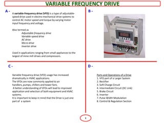
- 1. VARIABLE FREQUENCY DRIVE A- A variable-frequency drive (VFD) is a type of adjustable- B- speed drive used in electro-mechanical drive systems to control AC motor speed and torque by varying motor input frequency and voltage. Also termed as Adjustable-frequency drive Variable-speed drive AC drive Micro drive Inverter drive Used in applications ranging from small appliances to the largest of mine mill drives and compressors. C- D- Variable frequency drive (VFD) usage has increased Parts and Operations of a Drive dramatically in HVAC applications. 1. VFD part of a Larger System The VFDs are now commonly applied to air 2. Rectifier handlers, pumps, chillers and tower fans. 3. Soft Charge Circuit A better understanding of VFDs will lead to improved 4. Intermediate Circuit (DC Link) application and selection of both equipment and HVAC 5. Brake Circuit systems. 6. Inverter It is important to keep in mind that the Drive is just one 7. Pulse Width Modulation part of a system 8. Control & Regulation Section 1
- 2. VARIABLE FREQUENCY DRIVE A- B- Inside the VFD there are 4 major sections: Working Philosophy 1. Rectifier 2. Intermediate circuit (DC Link) Power first goes into the rectifier, where the 3-phase 3. Inverter and AC is converted into a rippling DC voltage. 4. Control/regulation. The intermediate circuits then smoothens and holds the DC Voltage at a constant level or energy source This fourth section, control for the inverter. and regulation, interfaces with the other 3 sections The last section, the inverter, uses the DC voltage to pulse the motor with varying levels of voltage and current depending upon the control circuit. The pattern of the pulses going to the motor makes it appear similar to an AC sinusoidal waveform. C- D- Rectifier rectifier section which is made up of a group of gated diodes (silicon rectifiers or SCRs). Diodes (D1 through D6) allow current to flow only in one direction when enabled by the gate signal. In this diagram, the AC power on L1 goes into Diodes D1 and D2. Because of the position of these diodes, current flow can only go up. The D1 diode conducts when the AC is positive and D2 conducts when the AC goes negative. This drives the top line (+) more positive and the bottom line (-) more negative. Diodes D3 and D4 convert L2 power to DC and Diodes D5 and D6 convert L3. A volt ohmmeter or VOM can be used to measure this DC voltage. In this type of circuit, the DC voltage is 1.35 times the AC line voltage. 2
- 3. VARIABLE FREQUENCY DRIVE A- B- Rectifiers may utilize diodes, silicon controlled rectifiers (SCR), or transistors to rectify power. Diodes are the simplest device and allow power to flow anytime voltage is of the proper polarity. Silicon controlled rectifiers include a gate circuit that enables a microprocessor to control when the power may begin to flow, making this type of rectifier useful for solid-state starters as well C- Soft Charge Circuit D- > used to power up the drive when power is applied, the inrush of current is restricted going to the large capacitors in the DC Link, so that they may charge up slowly soft charge circuit on some of the VFDs has a resistor or two in line with the current to slowly allow charging of the capacitors Once main power is applied to the drive, the SCRs in the main rectifier section remain off. The much smaller rectifier section in the soft charge circuit starts, applying DC power through the current resistors charging up the capacitors in the DC Link. When these capacitors are charged to the DC voltage minimum value, the control section starts the firing of the SCRs in the main rectifier. Because of the amp draw through the current resistors in the soft charge 3 circuit, time is needed to cool them off,
- 4. VARIABLE FREQUENCY DRIVE A- Intermediate Circuit (DC Link) B- Brake Circuit power storage facility for the next section, the inverter section. Two major components : capacitors and coils also known as Dynamic Braking, is used with devices Coils are essential to reduce harmonic noise. that need to stop or change directions quickly, such as conveyors, hoists and centrifuges An additional IGBT transistor is used to remove extra power coming back into the drive when the motor, which has a large inertia, is stopping or changing direction C- Inverter D- Pulse Width Modulation The DC voltage from the intermediate section and, with the help of the control section, fires each set of IGBT (Insulated Gate Bipolar Transistors) to the U, V and W terminals of the motor. This firing of the IGBTs is known as Pulse Width Modulation (PWM). The switching-pattern shown above is known as pulse width modulation or PWM. As the length of time is increased for the IGBT to be ON and then OFF, the motor responds to it as a sinusoidal waveform. The positive IGBT fires first in the diagram followed by its negative counterpart. Only one motor terminal (U) is shown but the same type of activity would appear on V and W. 4
- 5. VARIABLE FREQUENCY DRIVE A- B- Control & Regulation Section The control section coordinates and regulates signals inside the drive. This is where numerous calculations are completed to properly switch the IGBTs. This control section uses Vector technology, which separates the torque producing current from the magnetizing current. Without the drive, the only signal the motor sees is ON (50Hz/60Hz) or OFF (0Hz). With a drive the motor can operate with 20Hz, 40Hz, 60Hz, 90Hz or any frequency in between, making it much more adaptable to any application C- D- 5