Variable frequency drives (vfd)
•Download as PPTX, PDF•
0 likes•252 views

This is most commonly used equipment in industries to perform desired operation with high precision and accuracy.

Recommended
More Related Content
What's hot
What's hot (20)
Similar to Variable frequency drives (vfd)
Similar to Variable frequency drives (vfd) (20)
More from Ujjwal Choubey
Recently uploaded
Recently uploaded (20)
Variable frequency drives (vfd)
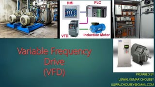
- 1. PREPARED BY UJJWAL KUMAR CHOUBEY UJJWALCHOUBEY@GMAIL.COM
- 2. Variable frequency drive (VFD) A Variable Frequency Drive (VFD) is a type of motor controller that drives an electric motor by varying the frequency and voltage supplied. Other names for a VFD are variable speed drive, adjustable speed drive, adjustable frequency drive, AC drive, microdrive, and inverter.
- 3. Why VFD? As we all know, the frequency (hertz) is directly related to the motor’s speed (RPM). In other words, the faster the frequency, the faster the RPM. If an application does not require an electric motor to run at full speed, the VFD can be used to ramp down the frequency and voltage to meet the requirements of the electric motor’s load. According to application motor’s speed requirements changes, the VFD can simply turn up or down the motor speed to meet the speed requirement. Hence, it is to control the motor with respect to application and safety.
- 4. Circuit The Circuit of VFD can be divided into 3 parts: 1. Rectifier 2. Filter 3. Inverter
- 5. Working As shown in previous slide circuit, the VFD begins with the 3-phase AC input supply which go through rectifier consisting Diodes that convert AC voltage to DC voltage. Then after, it passes through filter which consists of capacitors. This cleans the supply by removing noise and passes the clean supply to inverter. The inverter contains transistor which converts DC supply back AC, and send it to the motor for operation.
- 6. Working Now, about controlling of VFD. The regulator is attached to the inverter which varies the frequency and adjust the speed according to application. Also one can explore options of ramp up and ramp down, which make sure of safe going application.
- 7. Parameter and controlling Control methods The control capabilities can be classified into three groups: 1. Volts-per-hertz control 2. Self-sensing vector control 3. Closed-loop vector control
- 8. Parameter and controlling Volts-per-hertz control Volts-per-Hertz (V/f) control is the most commonly used motor control method. V/f control fixes the drive’s output to a predefined voltage and frequency relation for the motor to follow as the VFD’s speed command is adjusted. V/f control is commonly used for systems that do not require precise speed control, such as fans or pumps. The slight change in speed does little to impact the overall system performance as other drive programming will adjust the speed to maintain system demand.
- 9. Parameter and controlling Self-sensing vector control Self-sensing vector control is a control method that provides fine-tuned control of the motor’s speed. The complicated algorithms are used to monitor, interpret and respond to current feedback to provide precise motor control. Self-sensing vector control methods improves process control and reduces maintenance. This control regulates motor speed within 1/200th of motor rated speed, provide dynamic speed control, also limits current and torque without external devices. The VFD requires specific motor information, such as motor no-load current, resistance, and inductances to provide this motor control.
- 10. Parameter and controlling Closed-loop vector control Closed-loop vector control is the most advanced motor control method. The closed-loop vector control uses a motor encoder to provide precise speed feedback and eliminate any error in VFD control responding to current feedback. Closed-loop vector control’s add speed feedback signal to maximize process control and minimize maintenance. This allows for precise speed control down to one RPM, high starting torque at zero speed, zero speed control, and torque regulation.
- 11. Parameter and controlling Acceleration and deceleration times A VFD starts and stops the motor based on programmed acceleration and deceleration times. These times or ramp rates define how long the drive will take to get from zero to maximum frequency. Based on the inertia of the load, it is possible to start/stop a load quicker than what allowed based on the current capabilities of the motor. Aggressive acceleration/deceleration rates will lead to higher currents that may max the drive and motor and lead to overload or overcurrent faults. Setting the correct acceleration and deceleration time ensures proper system performance while ensuring no fault operation.
- 12. Parameter and controlling Speed and run source A VFD requires two things at every moment of its operation: a run command and speed reference. The run command tells the drive it should operate the motor, while speed reference tells the VFD what frequency to run. Setting the VFD’s speed and run command is more about how one chooses to run the motor. Each source has its own benefit: A voltage reference is simple to generate and easy to understand, while current signals propagate longer distances and being easily affected by nearby electrical noise, other avenues of control are through direct keypad or via network communications.
- 13. Parameter and controlling Fault Reset To maintain product lifetime and prevent failure, VFDs incorporate and trigger faults to protect themselves. Many VFDs incorporate automatic fault reset capabilities. This feature allows the drive to detect a condition outside the scope of its programming and trigger a fault to protect itself, the motor, and the rest of the mechanical system. The purpose of the auto reset is to overcome nuisance faults and maintain continuous operation.
- 14. Advantages Keeps starting current in control Helps in controlling operating speed and acceleration Limits and adjusts torque Saves energy and cost
- 15. Disadvantages Upfront cost of a VFD can be relatively high depending on how large your system is. Dramatically increased noise Excessive vibration Can reduce the service factor on the motor it’s used on