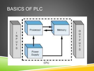
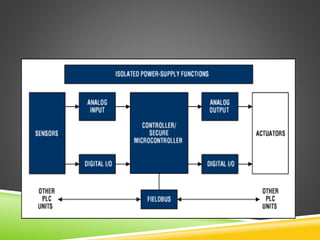
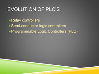
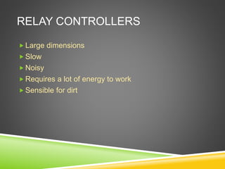
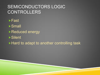
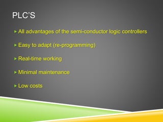
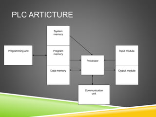
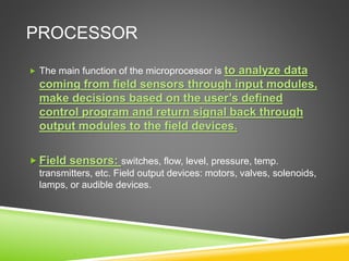
PLC ARCHITECTURE AND
HARDWARE COMPONENTS
PRESENTED BY:
Akshay Dhole
Mechatronics (SMBS)
13mmt1013
INDEX
 Introduction
 Basics of PLC
 PLC evolution
 Relays
 Semiconductors
 PLC
 PLC Architecture
 Hardware Components
 Advantages
 Disadvantages
INTRODUCTION
 A Programmable Logic Controller (PLC) is a specialized
computing system used for control of industrial machines
and processes.
 A PLC is a computer designed to work in an industrial
environment
 Equipped with special input/output interfaces
 Programmed using a control programming language.
BASICS OF PLC
EVOLUTION OF PLC’S
Relay controllers
Semi-conductor logic controllers
Programmable Logic Controllers (PLC)
RELAY CONTROLLERS
 Large dimensions
 Slow
 Noisy
 Requires a lot of energy to work
 Sensible for dirt
SEMICONDUCTORS LOGIC
CONTROLLERS
Fast
Small
Reduced energy
Silent
Hard to adapt to another controlling task
PLC’S
 All advantages of the semi-conductor logic controllers
 Easy to adapt (re-programming)
 Real-time working
 Minimal maintenance
 Low costs
PLC ARTICTURE
Program
memory
Data memory
Processor
Communication
unit
Input moduleProgramming unit
Output module
System
memory
PROCESSOR
 The main function of the microprocessor is to analyze data
coming from field sensors through input modules,
make decisions based on the user’s defined
control program and return signal back through
output modules to the field devices.
 Field sensors: switches, flow, level, pressure, temp.
transmitters, etc. Field output devices: motors, valves, solenoids,
lamps, or audible devices.
MEMORY
 System memory
 ROM (Read Only Memory)
 PROM (Programmable Read Only Memory)
 EPROM (Erasable Programmable Read Only
Memory)
 EEPROM (Electric Erasable Programmable ROM)
 Program/Data memory
 RAM (Random Access Memory)
SYSTEM MEMORY
 System memory includes an area called the
EXECUTIVE, composed of permanently-stored
programs that direct all system activities, such as execution of
the users control program, communication with peripheral
devices, and other system activities.
 The system memory also contains the routines that implement
the PLC’s instruction set, which is composed of specific
control functions such as logic, sequencing, timing, counting, and
arithmetic.
 System memory is generally built from read-only memory
devices.
ROM
 Read Only Memory
 A non-volatile memory. It has the ability to retain stored
information when power is removed, accidentally or intentionally.
A ROM does not require battery back-up.
 Read only indicates that the information stored in memory can be
read only and cannot be changed. Information in ROM is placed
there by the manufacturer for the internal use and
operation of the PLC.
PROM
 Programmable ROM
 Allows initial and/or additional information to be
written into the chip.
 PROM may be written into only once after being
received from the PLC manufacturer; programming is
accomplish by pulses of current.
 The current melts the fusible links in the device,
preventing it from being reprogrammed. This type of
memory is used to prevent unauthorized program
changes.
EEPROM
 Electrically EPROM
 Also referred to as E2PROM, is a chip that can be programmed
using a standard programming device and can be
erased by the proper signal being applied to the erase pin.
 EEPROM is used primarily as a non-volatile backup for
the normal RAM memory. If the program in RAM is
lost or erased, a copy of the program stored on an
EEPROM chip can be down loaded into the RAM.
PROGRAM/DATA MEMORY
 The program and data memories are called together
application memory.
 The data memory stores any data associated with the
user’s control program, such as system input and output
status data, and any stored constants, variables, or preset values.
The data memory is where data is monitored, manipulated, and
changed for control purposes.
 The user program area is where the programmed
instructions entered by the user are stored as an
application control program.
RAM
 Random Access Memory (Read/Write)
 A volatile memory, that is one that loses its stored information
when power is removed.
 Even momentary losses of power will erase any
information stored or programmed on a volatile memory
chip.
 Read/write indicates that the information stored in the
memory can be retrieved or read, while write indicates that the
user can program or write information into the memory.
 The words random access refer to the ability of any location
(address) in the memory to be accessed or used. Ram memory
is used for both the user memory (ladder diagrams) and
storage memory in many PLC’s.
 RAM memory must have battery backup to retain or
protect the stored program.
TYPES OF RAM MEMORY
 MOS (Metal Oxide Semiconductor)
 HMOS (High Density, short channel MOS )
 CMOS (Complimentary MOS)
 The CMOS-RAM is probably one of the most popular, because it
has a very low current drain when not being accessed
(15microamps.), and the information stored in memory can be
retained by as little as 2Vdc.
INPUT/OUTPUT MODULES
 The I/O interface section of a PLC connects it to
external field devices.
 The main purpose of the I/O interface is to condition the
various signals received from or sent to the external
input and output devices.
 Input modules converts signals from discrete or analog
input devices to logic levels acceptable to PLC’s processor.
 Output modules converts signal from the processor to
levels capable of driving the connected discrete or analog
output devices.
DC INPUT MODULE
Standard Digital Input signals: 24V
Current
limiting
resistor
Opto-
isolator
Buffer,
filter,
hysteresis
circuits
DC input Processor
Used to
drop the
voltage to
logic level
Prevents voltage transients from
damagigng the processor.
Helps to reduce the effects of
electrical noise.
AC INPUT MODULE
Standard Analog Input signals: 4-20mA; 0-10V
Rectifier,
Resistor
Network
Opto-
isolator
Buffer,
filter,
hysteresis
circuits
AC input Processor
Converts the AC
input to DC and
drops the voltage
to logic level
Prevents voltage transients from
damagigng the processor.
Helps to redice the effects of
electrical noise.
DC/AC OUTPUT MODULE
Standard Analog Output signals: 4-20mA; 0-5V; 0-10V
TTL
circuits
Opto-
isolator
AplifierProcessor Output
COMMUNICAITON UNIT
Manages the communication between the PLC &
 the controlled process,
 an other PLC,
 a PC,
 different peripheries.
Used ports:
 Serial (RS 232, RS 422, RS 485)
 Ethernet
SERIAL PORTS
 RS 232
 Used in short-distance computer
communications, with the majority of computer
hardware and peripherals.
 Has a maximum effective distance of
approx. 30 m at 9600 baud.
 RS 422 / RS 485
Used for longer-distance links, often
between several PCs in a distributed system. RS
485 can have a maximum distance of about
1000 meters.
ETHERNET: LOCAL AREA NETWORK
(LAN)
 Local Area Network provides a physical link
between all devices plus providing overall data
exchange management or protocol, ensuring that each
device can “talk” to other machines and understand data received
from them.
 LANs provide the common, high-speed data
communications bus which interconnects any or
all devices within the local area.
HARDWARE COMPONENTS
CONTENTS
 I/O Section
 I/O Modules
 Discrete
 Analog
 Special
 Specifications
 Memory
 Design
 Types
I/O SECTION
 Power Supply
 unaddressed (not typically part of rack)
 Processor in slot 0
 I/O in non-zero slots
LOGICAL RACK
 Image Table or File
 File I for input
 File O for output
 PLC-5 -- Octal
 Addressing
 SLC-500 – Decimal Addressing
REMOTE I/O RACK
ADDRESS ELEMENT
 Type
 File Type
 I for Input File
 O for Output File
 Others covered latter
 Slot
 Rack Number
 Slot Number
 Word or Bit
 Identifies the actual
 terminal connection
 Discrete module use
 one word and thus number specifies bit
COMMON DISCRETE I/O RATINGS
INPUT MODULES PERFORM
Senses when a signal is received from a
sensor on the machine
 Convert the input signal to correct logic level
 Isolates PLC from fluctuations in input signal
voltage (logic level noise)
 Sends a logic signal to processor indicating which sensor
originated the signal
AC INPUT CIRCUIT
OUTPUT MODULE PERFORM
Convert the logic level signal to correct
external signal
 Isolates PLC from fluctuations in output
signal voltage (logic level noise)
 Indicates output is active via lamp
AC OUTPUT CIRCUIT
SINKING & SOURCING
SPECIAL I/O MODULES
 High-Speed Counter Module
 Thumb-Wheel Module
 TTL Module
 Encoder-Counter Module
 BASIC or ASCII Module
 Stepper-Motor Module
 BCD-Output Module
 PID Module
 Servo Module Communications Module
 Language Module
 Speech Module
I/O SPECIFICATIONS
Nominal Input
Voltage
 On-State Input Voltage Range
 Nominal Current per Input
 Ambient Temperature Rating
 Input Delay
 Nominal Output Voltage
 Output Voltage range
 Maximum Output
 Current Rating per
 Output and Module
 Maximum Surge
 Current per Output
 Off-State Leakage Current per Output
 Electrical Isolation
 Number of Inputs and Outputs per Card
 Backplane Current Draw
 Resolution
 Input Impedance and Capacitance
 Common Mode
 Rejection Ratio
PROCESSOR MODE (STATE)
RUN Position
 Places processor in RUN mode
 Executes the ladder program and energizes output
devices
 Prevents you from performing online program
editing in this position
 Prevents you from using a programmer/operator
interface device to change processor mode
 PROG Position
 Places processor in program mode
 Prevents processor from scanning or executing the ladder program
 Controller outputs de-energized
 Allows program entry and edit
 Prevents you from using
 programmer/operator interface to
 changing mode
 REM Position
 Places processor in remote mode: Remote Run, Remote Program,
or Remote Test
 Allows you to change the processor mode with programmer/operator
interface device
 Allows you to perform online program editing
WATCH ELECTRO-STATIC DISCHARGE
 Ground yourself by touching ground
 conductor
 Use wrist strap that is grounded
 Handle Cards/Modules by edge
 Don’t touch circuit components
 Use conductive (static-safe) work bench top
MEMORY TYPES
ROM (Read-Only Memory)
 RAM (Random Access Memory)
 PROM (Programmable Read-Only Memory)
 EPROM (Erasable PROM)
 EEPROM (Electrical Erasable PROM) or Flash
ADVANTAGES
Increased Reliability
More Flexibility
Lower Cost
Faster Response
Easier to troubleshoot
Remote control capability
Communication Capability
DISADVANTAGES
 In contrast to microcontroller systems that have what is
called an open architecture, most PLCs manufacturers
offer only closed architectures for their products
 PLC devices are proprietary, which means that parts
and software from one manufacturer can t easily be
used in combination with parts of another
manufacturer, which limits the design and cost options
can’t
THANK YOU
PLC ARCHITECTURE AND HARDWARE COMPONENTS

PLC ARCHITECTURE AND HARDWARE COMPONENTS

  • 1.
    PLC ARCHITECTURE AND HARDWARECOMPONENTS PRESENTED BY: Akshay Dhole Mechatronics (SMBS) 13mmt1013
  • 2.
    INDEX  Introduction  Basicsof PLC  PLC evolution  Relays  Semiconductors  PLC  PLC Architecture  Hardware Components  Advantages  Disadvantages
  • 3.
    INTRODUCTION  A ProgrammableLogic Controller (PLC) is a specialized computing system used for control of industrial machines and processes.  A PLC is a computer designed to work in an industrial environment  Equipped with special input/output interfaces  Programmed using a control programming language.
  • 4.
  • 6.
    EVOLUTION OF PLC’S Relaycontrollers Semi-conductor logic controllers Programmable Logic Controllers (PLC)
  • 7.
    RELAY CONTROLLERS  Largedimensions  Slow  Noisy  Requires a lot of energy to work  Sensible for dirt
  • 8.
  • 9.
    PLC’S  All advantagesof the semi-conductor logic controllers  Easy to adapt (re-programming)  Real-time working  Minimal maintenance  Low costs
  • 10.
    PLC ARTICTURE Program memory Data memory Processor Communication unit InputmoduleProgramming unit Output module System memory
  • 11.
    PROCESSOR  The mainfunction of the microprocessor is to analyze data coming from field sensors through input modules, make decisions based on the user’s defined control program and return signal back through output modules to the field devices.  Field sensors: switches, flow, level, pressure, temp. transmitters, etc. Field output devices: motors, valves, solenoids, lamps, or audible devices.
  • 12.
    MEMORY  System memory ROM (Read Only Memory)  PROM (Programmable Read Only Memory)  EPROM (Erasable Programmable Read Only Memory)  EEPROM (Electric Erasable Programmable ROM)  Program/Data memory  RAM (Random Access Memory)
  • 13.
    SYSTEM MEMORY  Systemmemory includes an area called the EXECUTIVE, composed of permanently-stored programs that direct all system activities, such as execution of the users control program, communication with peripheral devices, and other system activities.  The system memory also contains the routines that implement the PLC’s instruction set, which is composed of specific control functions such as logic, sequencing, timing, counting, and arithmetic.  System memory is generally built from read-only memory devices.
  • 14.
    ROM  Read OnlyMemory  A non-volatile memory. It has the ability to retain stored information when power is removed, accidentally or intentionally. A ROM does not require battery back-up.  Read only indicates that the information stored in memory can be read only and cannot be changed. Information in ROM is placed there by the manufacturer for the internal use and operation of the PLC.
  • 15.
    PROM  Programmable ROM Allows initial and/or additional information to be written into the chip.  PROM may be written into only once after being received from the PLC manufacturer; programming is accomplish by pulses of current.  The current melts the fusible links in the device, preventing it from being reprogrammed. This type of memory is used to prevent unauthorized program changes.
  • 16.
    EEPROM  Electrically EPROM Also referred to as E2PROM, is a chip that can be programmed using a standard programming device and can be erased by the proper signal being applied to the erase pin.  EEPROM is used primarily as a non-volatile backup for the normal RAM memory. If the program in RAM is lost or erased, a copy of the program stored on an EEPROM chip can be down loaded into the RAM.
  • 17.
    PROGRAM/DATA MEMORY  Theprogram and data memories are called together application memory.  The data memory stores any data associated with the user’s control program, such as system input and output status data, and any stored constants, variables, or preset values. The data memory is where data is monitored, manipulated, and changed for control purposes.  The user program area is where the programmed instructions entered by the user are stored as an application control program.
  • 18.
    RAM  Random AccessMemory (Read/Write)  A volatile memory, that is one that loses its stored information when power is removed.  Even momentary losses of power will erase any information stored or programmed on a volatile memory chip.  Read/write indicates that the information stored in the memory can be retrieved or read, while write indicates that the user can program or write information into the memory.  The words random access refer to the ability of any location (address) in the memory to be accessed or used. Ram memory is used for both the user memory (ladder diagrams) and storage memory in many PLC’s.  RAM memory must have battery backup to retain or protect the stored program.
  • 19.
    TYPES OF RAMMEMORY  MOS (Metal Oxide Semiconductor)  HMOS (High Density, short channel MOS )  CMOS (Complimentary MOS)  The CMOS-RAM is probably one of the most popular, because it has a very low current drain when not being accessed (15microamps.), and the information stored in memory can be retained by as little as 2Vdc.
  • 20.
    INPUT/OUTPUT MODULES  TheI/O interface section of a PLC connects it to external field devices.  The main purpose of the I/O interface is to condition the various signals received from or sent to the external input and output devices.  Input modules converts signals from discrete or analog input devices to logic levels acceptable to PLC’s processor.  Output modules converts signal from the processor to levels capable of driving the connected discrete or analog output devices.
  • 21.
    DC INPUT MODULE StandardDigital Input signals: 24V Current limiting resistor Opto- isolator Buffer, filter, hysteresis circuits DC input Processor Used to drop the voltage to logic level Prevents voltage transients from damagigng the processor. Helps to reduce the effects of electrical noise.
  • 22.
    AC INPUT MODULE StandardAnalog Input signals: 4-20mA; 0-10V Rectifier, Resistor Network Opto- isolator Buffer, filter, hysteresis circuits AC input Processor Converts the AC input to DC and drops the voltage to logic level Prevents voltage transients from damagigng the processor. Helps to redice the effects of electrical noise.
  • 23.
    DC/AC OUTPUT MODULE StandardAnalog Output signals: 4-20mA; 0-5V; 0-10V TTL circuits Opto- isolator AplifierProcessor Output
  • 24.
    COMMUNICAITON UNIT Manages thecommunication between the PLC &  the controlled process,  an other PLC,  a PC,  different peripheries. Used ports:  Serial (RS 232, RS 422, RS 485)  Ethernet
  • 25.
    SERIAL PORTS  RS232  Used in short-distance computer communications, with the majority of computer hardware and peripherals.  Has a maximum effective distance of approx. 30 m at 9600 baud.  RS 422 / RS 485 Used for longer-distance links, often between several PCs in a distributed system. RS 485 can have a maximum distance of about 1000 meters.
  • 26.
    ETHERNET: LOCAL AREANETWORK (LAN)  Local Area Network provides a physical link between all devices plus providing overall data exchange management or protocol, ensuring that each device can “talk” to other machines and understand data received from them.  LANs provide the common, high-speed data communications bus which interconnects any or all devices within the local area.
  • 27.
  • 28.
    CONTENTS  I/O Section I/O Modules  Discrete  Analog  Special  Specifications  Memory  Design  Types
  • 29.
    I/O SECTION  PowerSupply  unaddressed (not typically part of rack)  Processor in slot 0  I/O in non-zero slots
  • 30.
    LOGICAL RACK  ImageTable or File  File I for input  File O for output  PLC-5 -- Octal  Addressing  SLC-500 – Decimal Addressing
  • 31.
  • 32.
    ADDRESS ELEMENT  Type File Type  I for Input File  O for Output File  Others covered latter  Slot  Rack Number  Slot Number  Word or Bit  Identifies the actual  terminal connection  Discrete module use  one word and thus number specifies bit
  • 33.
  • 34.
    INPUT MODULES PERFORM Senseswhen a signal is received from a sensor on the machine  Convert the input signal to correct logic level  Isolates PLC from fluctuations in input signal voltage (logic level noise)  Sends a logic signal to processor indicating which sensor originated the signal
  • 35.
  • 36.
    OUTPUT MODULE PERFORM Convertthe logic level signal to correct external signal  Isolates PLC from fluctuations in output signal voltage (logic level noise)  Indicates output is active via lamp
  • 37.
  • 38.
  • 40.
    SPECIAL I/O MODULES High-Speed Counter Module  Thumb-Wheel Module  TTL Module  Encoder-Counter Module  BASIC or ASCII Module  Stepper-Motor Module  BCD-Output Module  PID Module  Servo Module Communications Module  Language Module  Speech Module
  • 41.
    I/O SPECIFICATIONS Nominal Input Voltage On-State Input Voltage Range  Nominal Current per Input  Ambient Temperature Rating  Input Delay  Nominal Output Voltage  Output Voltage range  Maximum Output
  • 42.
     Current Ratingper  Output and Module  Maximum Surge  Current per Output  Off-State Leakage Current per Output  Electrical Isolation  Number of Inputs and Outputs per Card  Backplane Current Draw  Resolution  Input Impedance and Capacitance  Common Mode  Rejection Ratio
  • 43.
    PROCESSOR MODE (STATE) RUNPosition  Places processor in RUN mode  Executes the ladder program and energizes output devices  Prevents you from performing online program editing in this position  Prevents you from using a programmer/operator interface device to change processor mode
  • 44.
     PROG Position Places processor in program mode  Prevents processor from scanning or executing the ladder program  Controller outputs de-energized  Allows program entry and edit  Prevents you from using  programmer/operator interface to  changing mode  REM Position  Places processor in remote mode: Remote Run, Remote Program, or Remote Test  Allows you to change the processor mode with programmer/operator interface device  Allows you to perform online program editing
  • 45.
    WATCH ELECTRO-STATIC DISCHARGE Ground yourself by touching ground  conductor  Use wrist strap that is grounded  Handle Cards/Modules by edge  Don’t touch circuit components  Use conductive (static-safe) work bench top
  • 46.
    MEMORY TYPES ROM (Read-OnlyMemory)  RAM (Random Access Memory)  PROM (Programmable Read-Only Memory)  EPROM (Erasable PROM)  EEPROM (Electrical Erasable PROM) or Flash
  • 47.
    ADVANTAGES Increased Reliability More Flexibility LowerCost Faster Response Easier to troubleshoot Remote control capability Communication Capability
  • 48.
    DISADVANTAGES  In contrastto microcontroller systems that have what is called an open architecture, most PLCs manufacturers offer only closed architectures for their products  PLC devices are proprietary, which means that parts and software from one manufacturer can t easily be used in combination with parts of another manufacturer, which limits the design and cost options can’t
  • 49.