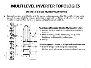
Simulation, Analysis & Open Loop
Constant V/Hz Speed Control of Multilevel
Inverter fed Induction Motor based on
SPWM Control
MOHAMMED ANNAS
1604-13-743-011
Power Electronics Systems (PES)
Under the Guidance of
Mr. J.E.Muralidhar, Associate Professor, EED
Muffakham Jah College of Engineering &
Technology, Banjara Hills, Hyderabad
Overview
 INTRODUCTION TO INVERTER
 CONCEPT OF MULTI LEVEL INVERTER
 MULTI LEVEL INVERTER TOPOLOGIES
 CASACADE H-BRIDGE INVERTER
 DIODE CLAPMED INVERTER
 FLYING CAPACITOR INVERTER
 SINUSOIDAL PWM TECHNIQUES
 IN-PHASE DISPOSITION (PD)
 PHASE OPPOSITION DISPOSITION (POD)
 ALTERNATE PHASE OPPOSITION DISPOSITION (APOD)
 MODELING OF PHASE DISPOSITION(PD) MODULATION TECHNIQUE
 GENERATION OF MODULATING SINE WAVE
 GENERATION OF TRIANGULAR CARRIER WAVE
 GENERATION OF FIRING PULSES FOR 3-LEVEL & 5-LEVEL INVERTER
 SIMULINK MODEL OF 3-LEVEL & 5-LEVEL DIODE CLAPMED INVERTER
 SIMULATION RESULTS
2
Overview
 Performance characteristics of induction motor connected to
Conventional 2-Level and Diode Clamped multi-level inverter
a) On RATED Load
b) On Variable Load
 Study of Transients During Starting of 3-Phase I.M.
 MATLAB Code for generating OPEN LOOP controlled Speed-Torque
Characteristics of 3-Phase I.M.
 Open Loop V/Hz Speed Control of 2-level & 5-level Inverter fed I.M.
 CONCLUSION
 REFERENCES
3
INTRODUCTION TO INVERTER
• A power inverter, or inverter, is an electronic device or circuitry that
changes direct current (DC) to alternating current (AC).
• The input voltage, output voltage and frequency, and overall power handling
depend on the design of the specific device or circuitry. The inverter does not
produce any power; the power is provided by the DC source.
4
CONCEPT OF MULTI-LEVEL INVERTER
 Mostly a two-level inverter is used in order to generate the AC voltage from DC voltage
 A two-level Inverter creates two different voltages for the load---
If Input Voltage is Vdc
Then it produces output as +Vdc/2 AND –Vdc/2 based on switching of power devices.
 This method of generating AC output seems to be Effective but posses following drawbacks:
• High Harmonic Distortion in Output Voltage.
• High dv/dt.
3-Phase two Level Inverter 2-Level Line Voltage Output Waveform (one leg)
5
CONCEPT OF MULTI-LEVEL INVERTER
In order to create a smoother stepped output waveform, more than two voltage levels
are combined together and the output waveform obtained in this case has lower dv/dt
and also lower harmonic distortions.
2-Level output 3-Level Output 5-Level Output
Smoothness of the waveform is proportional to the voltage levels, as we increase the
voltage level the waveform becomes smoother but the complexity of controller circuit
and components also increase.
Voltage Waveform Type Number of levels
Line-Line Voltage 0 Level, +ve or -ve levels
Phase-Neutral Voltage 0 Level, +ve Levels & -ve Levels
6
MULTI LEVEL INVERTER TOPOLOGIES
 The elementary concept of a multilevel converter to achieve higher power is to use a series
of power semiconductor switches with several lower voltage dc sources to perform the
power conversion by synthesizing a staircase voltage waveform.
 Capacitors, batteries, and renewable energy voltage sources can be used as the multiple dc
voltage sources.
 however, the rated voltage of the power semiconductor switches depends only upon the
rating of the dc voltage sources to which they are connected.
 There are several topologies of multilevel inverters available. The difference lies in the
mechanism of switching and the source of input voltage to the multilevel inverters. Three
most commonly used multilevel inverter topologies are:
• Cascaded H-bridge multilevel inverters
• Diode Clamped multilevel inverters
• Flying Capacitor multilevel inverters
 Advantages of Multilevel Inverters:
• Better Staircase waveform Quality.
• Lower Common-Mode (CM) Voltage.
• Less Distorted Input Current.
• Possibility of Higher Switching Frequency.
7
MULTI LEVEL INVERTER TOPOLOGIES
CASCADE H-BRIGDE MULTI LEVEL INVERTER
 Each cell contains one H-bridge and the output voltage generated by this multilevel inverter is
actually the sum of all the voltages generated by each cell i.e. if there are k cells in a H-bridge
multilevel inverter then number of output voltage levels will be 2k+1.
Advantages of Cascade H Bridge Multilevel Inverters
• Output voltages levels are doubled the number of
sources
• Manufacturing can be done easily and quickly
• Packaging and Layout is modularized.
• Cheap
Disadvantages of Cascade H Bridge Multilevel Inverters
• Every H Bridge needs a separate dc source.
• Limited applications due to large number of sources.
8
MULTI LEVEL INVERTER TOPOLOGIES
DIODE CLAMPED MULTI LEVEL INVERTER
 This topology uses clamping diodes in order to limit the voltage stress of power devices.
 It was first proposed in 1981 by Nabae, Takashi and Akagi.
 A k level diode clamped inverter needs
• (2k – 2) switching devices,
• (k – 1) input voltage source and
• (k – 1) (k – 2) diodes in order to operate.
 Vdc is the voltage present across each diode and the switch.
Three level diode clamp multi-level inverter (one leg) Switching states in one leg of the three-level diode clamped inverter
9
MULTI LEVEL INVERTER TOPOLOGIES
DIODE CLAMPED MULTI LEVEL INVERTER
Five level diode clamp multi-level inverter (one leg) Switching states in one leg of the five-level diode clamped inverter
Advantages of Diode Clamped Multilevel Inverters
• Capacitance of the capacitors used is low.
• Back to back inverters can be used.
• Capacitors are pre charged.
• At fundamental frequency, efficiency is high.
Disadvantages of Diode Clamped Multilevel Inverters
• Clamping diodes are increased with the increase of each level.
• Dc level will discharge when control and monitoring are not precise.
10
MULTI LEVEL INVERTER TOPOLOGIES
FLYING CAPACITOR MULTILEVEL INVERTER
 This configuration is quite similar to previous one except the difference that here flying capacitors is
used in order to limit the voltage instead of diodes.
 The input DC voltages are divided by the capacitors here.
 The voltage over each capacitor and each switch is Vdc.
 A k level flying capacitor inverter requires
• (k - 1) x (k - 2)/2 auxiliary capacitors per phase leg
• (2k – 2) switches and
• (k – 1) number of capacitors in order to operate.
 Switching state is same as diode clamped Multilevel Inverter
Advantages of Flying Capacitor Multilevel Inverters
• Static var generation is the best application of Capacitor Clamped
Multilevel Inverters.
• For balancing capacitors’ voltage levels, phase redundancies are
available.
• We can control reactive and real power flow
Disadvantages of Flying Capacitor Multilevel Inverters
• Voltage control is difficult for all the capacitors
• Complex startup
• Switching efficiency is poor
• Capacitors are expansive than diodes
Three level Flying Capacitor multi-level inverter (one leg)
11
Sinusoidal PWM Technique
 In this technique, an isosceles triangle carrier wave of frequency fc is compared with the fundamental
frequency fr sinusoidal modulating wave, and the points of intersection determines the switching points of
power devices.
 Two important parameters of the design process are
• Amplitude Modulation Index Ma=
𝐕𝐫
𝐕𝐜
where Vr = Peak amplitude of reference control signals
Vc = Peak amplitude of the Triangular carrier wave.
• Frequency Modulation Index Mf =
𝐟𝐜
𝐟𝐫
where fc = frequency of the carrier wave
fr = reference sinusoidal signal frequency.
 Ma determines the magnitude of output Voltage
 fr controls the frequency of output voltage
 fc determines switching frequency of power semiconductor devices. 12
Sinusoidal PWM Technique
 Types of Multiple Carrier-based SPWM Techniques:
Sinusoidal PWM can be classified according to carrier and modulating signals.
This work used the intersection of a sine wave with a triangular wave to generate firing pulses.
There are many alternative strategies, such as:
I. In-Phase Disposition (PD)
II. Phase Opposition Disposition (POD)
III. Alternative Phase Opposition Disposition (APOD)
I. In-Phase Disposition (PD):
In this technique, All the triangular carrier waves are In-Phase with each other.
13
Sinusoidal PWM Technique
II. Phase Opposition Disposition (POD):
In this technique, the carrier signal above Zero reference are In-Phase but Phase shifted by 180° from those
carrier signals which are below zero reference.
III. Alternative Phase Opposition Disposition (APOD):
In this method, each carrier signal is phase shifted by 180° from the adjacent carrier signal.
14
MODELING OF PHASE DISPOSITION(PD)
MODULATION TECHNIQUE
GENERATION OF MODULATING SINE WAVE
In order to generate fundamental component of output voltage at 50Hz frequency, the frequency
of reference sine wave is set to 50Hz itself.
This option is used to apply
PHASE SHIFT in Sine wave
in terms of RADIANS.
120° = 2*pi/3
240° = -2*pi/3
This option is
used to apply
desired
frequency of Sine
wave in terms of
RADIANS 15
MODELING OF PHASE DISPOSITION(PD)
MODULATION TECHNIQUE
GENERATION OF TRIANGULAR CARRIER WAVE
Let the switching frequency, fs = 1.1 kHz
Fundamental(Output) Frequency, fr = 50 Hz
Hence, Frequency Modulation ratio, Mf = 22(
𝑓 𝑠
𝑓 𝑟
) which means there exist 22 cycles of triangular wave
for each cycle of Sine wave.
Time Period, T 𝑠 =
1
𝑓 𝑠
=
1
1100
= 9.09 * 10-4 sec.
Let, 𝑥 =
𝑇 𝑠
4
= 0.0002273 sec.
16
MODELING OF PHASE DISPOSITION(PD) MODULATION
TECHNIQUE
GENERATION OF FIRING PULSES
 PD SPWM GENERATION FOR 3-LEVEL INVERTER :
• Three level pulse width modulated waveforms can be generated by sine-carrier PWM.
• Sine carrier PWM is generated by comparing the three reference control signals (one for each phase) with two
triangular carrier waves.
Vdc/2 , Vref,i > Vtri,1
Vio = 0 , Vtri,1 > Vref,i > Vtri,2 Where i= a, b or c phase
-Vdc/2 , Vtri,2 > Vref,
Simulated SPWM output for 3-Level Inverter 17
MODELING OF PHASE DISPOSITION(PD) MODULATION
TECHNIQUE
GENERATION OF FIRING PULSES
 PD SPWM GENERATION FOR 3-LEVEL INVERTER :
Simulink Model for 3-Level PD SPWM Generation Firing Pulses for Upper & Lower Switches for a-Phase of 3-Level inverter
18
MODELING OF PHASE DISPOSITION(PD) MODULATION
TECHNIQUE
GENERATION OF FIRING PULSES
 PD SPWM GENERATION FOR 5-LEVEL INVERTER :
• Five level pulse width modulated waveforms can be generated comparing the three reference
control signals (one for each phase) with four triangular carrier waves.
Vdc/2 , Vref,i > Vtri,1
Vdc/4 , Vref,i > Vtri,2
Vio = 0 , Vtri2 > Vref,i > Vtri,3
-Vdc/4 , Vtri,3 > Vref,i
-Vdc/2 , Vtri,4 > Vref,i
Where i = a, b or c phase
Simulated SPWM output for 5-Level Inverter
19
MODELING OF PHASE DISPOSITION(PD) MODULATION
TECHNIQUE
GENERATION OF FIRING PULSES
 PD SPWM GENERATION FOR 5-LEVEL INVERTER :
Simulink Model for 5-Level PD SPWM Generation
Firing Pulses
for UPPER 4
Switches
Firing Pulses
for LOWER 4
Switches
20
MODELING OF PHASE DISPOSITION(PD) MODULATION
TECHNIQUE
GENERATION OF FIRING PULSES
 PD SPWM GENERATION FOR 5-LEVEL INVERTER :
Firing Pulses for Upper Switches(S1, S2, S3 & S4) for a-Phase of 3-Level inverter
21
SIMULATION MODELS OF DIODE CLAMPED MULTILEVEL INVERTER
Specifications(For both 3-Level & 5-Level Inverter):
• Supply Voltage = 200V
• Fundamental Frequency (fr) = 50 Hz
• Switching Frequency (fs) = 1.1 KHz
• Amplitude Modulation Index (Ma) = Variable
• Frequency Modulation Index (Mf) = 22
Simulink Model of THREE Level Diode Clamped SPWM Inverter 22
SIMULATION MODELS OF DIODE CLAMPED MULTILEVEL INVERTER
Simulink Model of FIVE Level Diode Clamped SPWM Inverter 23
SIMULATION RESULTS
Simulated Line voltage of 3-Level diode clamped inverter
Harmonic Spectrum of 3-Level diode clamped inverter for R= 25Ω/phase and ma=0.9 24
SIMULATION RESULTS
Simulated Line voltage of 5-Level diode clamped inverter
Harmonic Spectrum of 5-Level diode clamped inverter for R= 25Ω/phase and ma=0.9 25
SIMULATION RESULTS
Ma 3-Level Inverter Line Voltage 5-Level Inverter Line Voltage
0.5
0.8
1.1
26
SIMULATION RESULTS
Comparison of the calculated Line voltage THD for fixed R Load
Modulation Index
(ma)
% THD
3-Level
% THD
5-Level
1.1 31.94 15.93
1 35.25 17.23
0.9 39.20 17.45
0.8 42.03 21.73
0.7 44.30 24.18
0.6 49.17 26.43
0.5 68.54 35.29
27
PERFORMANCE CHARACTERISTICS OF 2-LEVEL AND
DIODE CLAMPED MULTI INVERTER FED INDUCTION
MOTOR
The Performance Characteristics of Induction Motor is analyzed when loaded with
a) Rated Torque
b) Variable Torque
Specifications of Induction Motor: 4kW, 400V, 50Hz and 1500 RPM
(a) Rated Torque ---
𝑘𝑊 =
2∗𝜋∗𝑁
60
∗ 𝑇rated
Hence, Trated = 26.71 N-m
(b) Variable Torque---
In this case, Load Torque is applied in the form of steps i.e. different magnitude at different time.
Variable Load Torque 28
Simulink Model of Two Level SPWM Inverter fed Induction motor Drive
PERFORMANCE CHARACTERISTICS OF 2-LEVEL
INVERTER FED INDUCTION MOTOR
29
• Stator Current, Rotor Current, Speed & Electromagnetic Torque variations at RATED Load Torque
(26.71 N-m)
Stator Current of 2-Level inverter fed I.M.
Rotor Current of 2-Level inverter fed I.M.
PERFORMANCE CHARACTERISTICS OF 2-LEVEL INVERTER FED INDUCTION
MOTOR
30
• Stator Current, Rotor Current, Speed & Electromagnetic Torque variations at RATED Load Torque
(26.71 N-m)
Speed Variation of 2-Level inverter fed I.M.
Electromagnetic Torque of 2-Level inverter fed I.M.
PERFORMANCE CHARACTERISTICS OF 2-LEVEL INVERTER FED INDUCTION
MOTOR
31
• Electromagnetic Torque variations at VARIABLE Load Torque
Variable Load Torque, Speed variation & Electromagnetic torque variation of 2-Level inverter fed I.M.
PERFORMANCE CHARACTERISTICS OF 2-LEVEL INVERTER FED INDUCTION
MOTOR
32
Simulink Model of Three Level Diode Clamped SPWM Inverter fed Induction motor Drive
PERFORMANCE CHARACTERISTICS OF 3-LEVEL DIODE
CLAMPED MULTI INVERTER FED INDUCTION MOTOR
33
• Stator Current, Rotor Current, Speed & Electromagnetic Torque variations at RATED Load Torque
(26.71 N-m)
Stator Current of 3-Level inverter fed I.M.
Rotor Current of 3-Level inverter fed I.M.
PERFORMANCE CHARACTERISTICS OF 3-LEVEL DIODE CLAMPED MULTI
INVERTER FED INDUCTION MOTOR
34
• Stator Current, Rotor Current, Speed & Electromagnetic Torque variations at RATED Load Torque
(26.71 N-m)
Speed Variation of 3-Level inverter fed I.M.
Electromagnetic Torque of 3-Level inverter fed I.M.
PERFORMANCE CHARACTERISTICS OF 3-LEVEL DIODE CLAMPED MULTI
INVERTER FED INDUCTION MOTOR
35
• Electromagnetic Torque variations at VARIABLE Load Torque
Variable Load Torque, Speed variation & Electromagnetic torque variation of 3-Level inverter fed I.M.
PERFORMANCE CHARACTERISTICS OF 3-LEVEL DIODE CLAMPED MULTI
INVERTER FED INDUCTION MOTOR
36
Simulink Model of Five Level Diode Clamped SPWM Inverter fed Induction motor Drive
PERFORMANCE CHARACTERISTICS OF 5-LEVEL DIODE
CLAMPED MULTI INVERTER FED INDUCTION MOTOR
37
• Stator Current, Rotor Current, Speed & Electromagnetic Torque variations at RATED Load Torque
(26.71 N-m)
Stator Current of 5-Level inverter fed I.M.
Rotor Current of 5-Level inverter fed I.M.
PERFORMANCE CHARACTERISTICS OF 5-LEVEL DIODE CLAMPED MULTI
INVERTER FED INDUCTION MOTOR
38
• Stator Current, Rotor Current, Speed & Electromagnetic Torque variations at RATED Load Torque
(26.71 N-m)
Speed Variation of 5-Level inverter fed I.M.
Electromagnetic Torque of 5-Level inverter fed I.M.
PERFORMANCE CHARACTERISTICS OF 5-LEVEL DIODE CLAMPED MULTI
INVERTER FED INDUCTION MOTOR
39
• Speed variations at VARIABLE Load Torque
Load Torque & speed variation of 5-Level Diode Clamped Inverter fed I.M.
PERFORMANCE CHARACTERISTICS OF 5-LEVEL DIODE CLAMPED MULTI
INVERTER FED INDUCTION MOTOR
INVERTER
LEVEL
Stator Current
(amps)
Speed(rpm)
Electromagnetic
Torque(N-m)
2 14.41 1384 33.14
3 12.46 1294 27.04
5 31.38 1500 30.24
• Magnitudes of Induction Motor Parameters for 2,3 & 5-level inverter at RATED Load Torque (26.71 Nm)
40
Comparison of Line-Line Voltage THD for 2, 3 & 5 Level
Inverter fed I.M.
The comparison between the total harmonic distortion with respect to the modulation
index for 2, 3 and 5-level Diode clamped inverter is shown below in figure. It can be
observed that the THD is lower in 5-level inverter.
41
Study of Transients during Starting of 3-Phase
Induction Motor
• A model of a 3-Phase induction motor was setup in MATLAB SIMULINK and the rotor and stator
currents, speed & electromagnetic torque were observed with different values of rotor and stator
resistances and impedances.
• Stator Inductance:
Low ~ 0.05mH
Medium ~ 0.7mH
High ~ 2mH
• Rotor Resistance:
Low ~ 0.1 ohm
High ~ 0.5 ohm
• Stator Resistance:
Low ~ 0.16 ohm
High ~ 0.8 ohm
All the simulations were made for Zero Load Torque. However, the inertia and
friction were taken into consideration.
42
Study of Transients during Starting of 3-Phase
Induction Motor
VALUE STATOR_I(amps) SPEED(rpm)
Low 49.79 1500
Medium 25.48 1499
High 25.9 1499
STATOR INDUCTANCE:
VALUE STATOR_I(amps) SPEED(rpm)
Low 26.62 1500
High 26.92 1496
ROTOR RESISTANCE:
VALUE STATOR_I(amps) SPEED(rpm)
Low 41.96 1500
High 9.665 1398
STATOR RESISTANCE:
43
Study of Transients during Starting of 3-Phase
Induction Motor
On the basis of the above outcomes, the following observations were
made:
• On increasing the motor inductance (either rotor or stator), the
transients lasted for longer period i.e., the machine took longer
time to achieve its steady state speed, current and torque. Also the
start was a bit jerky.
• On increasing the rotor resistance, there was no effect on the
steady state time but the machine started with lesser jerks, i.e.,
the fluctuations in the transient period was reduced. Also the
maximum torque occurred at a lower speed.
• On increasing the stator resistance, the steady state time
increased as well as the machine started with more jerks. Thus the
stator resistance must be kept as low as possible.
44
MATLAB Code for Generating OPEN LOOP Constant V/Hz speed
control Characteristics
function out = inductionconstVf()
Vll=input('Suppy Voltage (line to line) RMS value @ 50 Hz: ');
f2=input('Enter the second frequency: ');
f3=input('Enter the third frequency: ');
f4=input('Enter the fourth frequency: ');
f5=input('Enter the fifth frequency: ');
P=input('Enter the number of poles: ');
Rs=input('Stator Resistance: ');
Rr=input('Rotor Resistance: ');
Xs=input('Stator Leakage Reactance @ 50 Hz frequecny: ');
Xr=input('Rotor Leakage Reactance @ 50 Hz frequecny: ');
Ls=Xs/(2*pi*50);
Lr=Xr/(2*pi*50);
Vlnf1=Vll/(3^0.5);
Vlnf2=Vlnf1*f2/50;
Vlnf3=Vlnf1*f3/50;
Vlnf4=Vlnf1*f4/50;
Vlnf5=Vlnf1*f5/50;
Wsync1=4*pi*50/P;
Wsync2=4*pi*f2/P;
Wsync3=4*pi*f3/P;
Wsync4=4*pi*f4/P;
Wsync5=4*pi*f5/P;
45
MATLAB Code for Generating OPEN LOOP Constant V/Hz speed
control Characteristics
Tmf2=zeros(Wsync2*500+1,1);
Tmf3=zeros(Wsync3*500+1,1);
Tmf4=zeros(Wsync4*500+1,1);
Tmf5=zeros(Wsync5*500+1,1);
Tmf1=zeros(Wsync1*500+1,1);
m=1;
for Wrotor1=0:0.002:Wsync1
Tmf1(m)=(3*(((Vlnf1^2)*Rr/((Wsync1-Wrotor1)/Wsync1))/((Rs+Rr/((Wsync1-Wrotor1)/Wsync1))^2+(2*pi*50*Ls+2*pi*50*Lr)^2))/Wsync1);
%star connected
m=m+1;
end
m=1;
for Wrotor2=0:0.002:Wsync2
Tmf2(m)=(3*(((Vlnf2^2)*Rr/((Wsync2-Wrotor2)/Wsync2))/((Rs+Rr/((Wsync2-Wrotor2)/Wsync2))^2+(2*pi*f2*Ls+2*pi*f2*Lr)^2))/Wsync2);
m=m+1;
end
m=1;
for Wrotor3=0:0.002:Wsync3
Tmf3(m)=(3*(((Vlnf3^2)*Rr/((Wsync3-Wrotor3)/Wsync3))/((Rs+Rr/((Wsync3-Wrotor3)/Wsync3))^2+(2*pi*f3*Ls+2*pi*f3*Lr)^2))/Wsync3);
m=m+1;
end
m=1;
for Wrotor4=0:0.002:Wsync4
Tmf4(m)=(3*(((Vlnf4^2)*Rr/((Wsync4-Wrotor4)/Wsync4))/((Rs+Rr/((Wsync4-Wrotor4)/Wsync4))^2+(2*pi*f4*Ls+2*pi*f4*Lr)^2))/Wsync4);
m=m+1;
end
46
MATLAB Code for Generating OPEN LOOP Constant V/Hz speed
control Characteristics
m=1;
for Wrotor5=0:0.002:Wsync5
Tmf5(m)=(3*(((Vlnf5^2)*Rr/((Wsync5-Wrotor5)/Wsync5))/((Rs+Rr/((Wsync5-Wrotor5)/Wsync5))^2+(2*pi*f5*Ls+2*pi*f5*Lr)^2))/Wsync5);
m=m+1;
end
plot(Tmf1);
hold on;
plot(Tmf2);
plot(Tmf3);
plot(Tmf4);
plot(Tmf5);
hold off;
ylabel('Torque(N-m)');
xlabel('Rotor Speed(Rad/s) * 100');
end
47
Speed-Torque Characteristics for Open Loop Constant
V/Hz control of Induction Motor
48
Open Loop V/Hz Speed Control of 2-level
Inverter fed IM
• Comparison of speed at various Frequencies
• At 50Hz Frequency (1460 rpm)
• At 40Hz Frequency (1134 rpm)
• At 30Hz Frequency (752 rpm)
49
Open Loop V/Hz Speed Control of 2-level
Inverter fed IM
• Comparison of Torque at various Frequencies
• At 50Hz Frequency
• At 40Hz Frequency
• At 30Hz Frequency
50
Open Loop V/Hz Speed Control of 2-level
Inverter fed IM
• Comparison of Stator Current at various Frequencies
• At 50Hz Frequency ( 11.37 Amps)
• At 40Hz Frequency ( 9.7 Amps)
• At 30Hz Frequency ( 6.8 Amps)
51
Open Loop V/Hz Speed Control of 5-Level Diode
Clamped Inverter fed I.M.
• Comparison of speed at various Frequencies
• At 50Hz Frequency (1479 rpm)
• At 40Hz Frequency (1173 rpm)
• At 30Hz Frequency (873 rpm)
52
Open Loop V/Hz Speed Control of 5-Level Diode
Clamped Inverter fed I.M.
• Comparison of Torque at various Frequencies
• At 50Hz Frequency
• At 40Hz Frequency
• At 30Hz Frequency
53
Open Loop V/Hz Speed Control of 5-Level Diode
Clamped Inverter fed I.M.
• Comparison of Stator Current at various Frequencies
• At 50Hz Frequency ( 4.9 Amps)
• At 40Hz Frequency ( 4.6 Amps)
• At 30Hz Frequency ( 4.7 Amps)
54
%THD of Line Voltage, Stator Current & Speed for open loop V/Hz Control
Load Torque = 10 N-m with step time of 0.15 Simulation time
 2 level output --- 400.5AC 50Hz at 568.5 DC Input @ 0.9 Ma
 5 level output --- 400.1AC 50Hz at (179 * 4) DC Input @ 0.9 Ma
As can be observed form above waveforms, The V/Hz Speed control (open loop mode) can be
achieved just by varying MODULATION INDEX of SPWM.
Tabular Columns states that at various frequencies different speeds can be obtained by keeping V/f
ratio constant & also Electromagnetic Torque fluctuates near Rated Load Torque.
Frequency
(Hz)
2 * Ma
AC Supply
voltage (V)
V/f
Line
Voltage
%THD
Stator
Current
(A)
Speed
(rpm)
50 1.8 400.5 8.01 0.796*100 11.37 1460
40 1.16 321.4 8.035 1.219*100 9.7 1134
30 0.65 240.7 8.023 2.605*100 6.801 752
Frequency
(Hz)
2 * Ma
AC Supply
voltage(V)
V/f
Line
Voltage
%THD
Stator
Current
(A)
Speed
(rpm)
50 1.8 400.1 8.002 0.1744*100 4.919 1479
40 1.42 319.8 7.995 0.2432*100 4.653 1173
30 1.04 240.8 8.013 0.3351*100 4.753 873
55
CONCLUSION
 This Presentation briefly explains the theory of Phase Disposition Sinusoidal Pulse Width
Modulation (PDSPWM) for three and five level inverter.
 The simulation of 3-Level and 5-Level Diode clamped multilevel inverter was carried
using sinusoidal pulse width modulation (PWM).
 It has shown that reduction in line voltage THD takes place as we move from three level
inverter to five level inverter and performance of both inverters were investigated using
R Load.
 Also a comparison of %THD for both the inverters has been tabulated for different
values of amplitude modulation index (ma).
 Performance characteristics of induction motor connected to Conventional 2-Level and
Diode Clamped multi-level inverter has been studied and found that as the level of
inverter increases motor performance becomes better.
 Transient during starting of 3-Phase I.M. are studied for variable motor parameters.
 MATLAB Code is generated to plot the Speed-Torque Characteristics of Open Loop
controlled Induction Motor.
 Open loop constant V/Hz speed control of I.M. can be easily achieved from Multi Level
Inverters just by manually varying the MODULATION INDEX in SPWM.
56
REFERENCES
[1] J.-S. Lai and F. Z. Peng, “Multilevel converters—A new breed of power converters,” IEEE Trans. Ind. Appl., vol. 32,
no. 3, pp. 509–517, May/Jun. 1996.
[2] A. Nabae, I. Takahashi, and H. Akagi, “A new neutral-point clamped PWM inverter,” IEEE Trans. Ind. Appl., vol. IA-
17, no. 5, pp. 518–523, Sep./Oct. 1981.
[3] Jose Roriguez, Jih-Sheng, and Fang Zheng Peng, “Multilevel Inverter: A Survey of Topologies, Controls, and
Applications,” IEEE Transactions on Industrial Electronics, Vol. 49, No. 4, pp. 724-738August 2002.
[4] Andreas Nordvall, “Multilevel Inverter Topology Survey”, Master of Science Thesis in Electric Power Engineering,
Department of Energy and Environment, Division of Electric Power Engineering, CHALMERS UNIVERSITY OF
TECHNOLOGY, Goteborg, Sweden, 2011.
[5] Kapil Jain and Pradyuman Chaturvedi, “Matlab-based Simulation & Analysis of Three-level SPWM Inverter”,
International Journal of Soft Computing and Engineering (IJSCE), Volume-2, Issue-1, March 2012.
[6] Ritu chaturvedi, “A Single Phase Diode Clamped Multilevel Inverter and its Switching Function,” Journal of
Innovative trends in Science, Pharmacy & Technology, Vol.1(1), pp.63-66, 2014.
[7] Ashwini Kadam and A.N.Shaikh, “Simulation & Implementation Of Three Phase Induction Motor On Single Phase
By Using PWM Techniques”, International Journal of Engineering Research and General Science Volume 2, Issue 6,
pp.93-104, October-November, 2014.
[8] Bhabani Shankar Pattnaik, Debendra Kumar Dash and Joydeep Mukherjee, “Implementation Of PWM Based Firing
Scheme For Multilevel Inverter Using Microcontroller”, Bachelor Of Technology Thesis, Department Of Electrical
Engineering, National Institute Of Technology, Rourkela.
57
THANK YOU
58

M.E. Project PPT

  • 1.
    Simulation, Analysis &Open Loop Constant V/Hz Speed Control of Multilevel Inverter fed Induction Motor based on SPWM Control MOHAMMED ANNAS 1604-13-743-011 Power Electronics Systems (PES) Under the Guidance of Mr. J.E.Muralidhar, Associate Professor, EED Muffakham Jah College of Engineering & Technology, Banjara Hills, Hyderabad
  • 2.
    Overview  INTRODUCTION TOINVERTER  CONCEPT OF MULTI LEVEL INVERTER  MULTI LEVEL INVERTER TOPOLOGIES  CASACADE H-BRIDGE INVERTER  DIODE CLAPMED INVERTER  FLYING CAPACITOR INVERTER  SINUSOIDAL PWM TECHNIQUES  IN-PHASE DISPOSITION (PD)  PHASE OPPOSITION DISPOSITION (POD)  ALTERNATE PHASE OPPOSITION DISPOSITION (APOD)  MODELING OF PHASE DISPOSITION(PD) MODULATION TECHNIQUE  GENERATION OF MODULATING SINE WAVE  GENERATION OF TRIANGULAR CARRIER WAVE  GENERATION OF FIRING PULSES FOR 3-LEVEL & 5-LEVEL INVERTER  SIMULINK MODEL OF 3-LEVEL & 5-LEVEL DIODE CLAPMED INVERTER  SIMULATION RESULTS 2
  • 3.
    Overview  Performance characteristicsof induction motor connected to Conventional 2-Level and Diode Clamped multi-level inverter a) On RATED Load b) On Variable Load  Study of Transients During Starting of 3-Phase I.M.  MATLAB Code for generating OPEN LOOP controlled Speed-Torque Characteristics of 3-Phase I.M.  Open Loop V/Hz Speed Control of 2-level & 5-level Inverter fed I.M.  CONCLUSION  REFERENCES 3
  • 4.
    INTRODUCTION TO INVERTER •A power inverter, or inverter, is an electronic device or circuitry that changes direct current (DC) to alternating current (AC). • The input voltage, output voltage and frequency, and overall power handling depend on the design of the specific device or circuitry. The inverter does not produce any power; the power is provided by the DC source. 4
  • 5.
    CONCEPT OF MULTI-LEVELINVERTER  Mostly a two-level inverter is used in order to generate the AC voltage from DC voltage  A two-level Inverter creates two different voltages for the load--- If Input Voltage is Vdc Then it produces output as +Vdc/2 AND –Vdc/2 based on switching of power devices.  This method of generating AC output seems to be Effective but posses following drawbacks: • High Harmonic Distortion in Output Voltage. • High dv/dt. 3-Phase two Level Inverter 2-Level Line Voltage Output Waveform (one leg) 5
  • 6.
    CONCEPT OF MULTI-LEVELINVERTER In order to create a smoother stepped output waveform, more than two voltage levels are combined together and the output waveform obtained in this case has lower dv/dt and also lower harmonic distortions. 2-Level output 3-Level Output 5-Level Output Smoothness of the waveform is proportional to the voltage levels, as we increase the voltage level the waveform becomes smoother but the complexity of controller circuit and components also increase. Voltage Waveform Type Number of levels Line-Line Voltage 0 Level, +ve or -ve levels Phase-Neutral Voltage 0 Level, +ve Levels & -ve Levels 6
  • 7.
    MULTI LEVEL INVERTERTOPOLOGIES  The elementary concept of a multilevel converter to achieve higher power is to use a series of power semiconductor switches with several lower voltage dc sources to perform the power conversion by synthesizing a staircase voltage waveform.  Capacitors, batteries, and renewable energy voltage sources can be used as the multiple dc voltage sources.  however, the rated voltage of the power semiconductor switches depends only upon the rating of the dc voltage sources to which they are connected.  There are several topologies of multilevel inverters available. The difference lies in the mechanism of switching and the source of input voltage to the multilevel inverters. Three most commonly used multilevel inverter topologies are: • Cascaded H-bridge multilevel inverters • Diode Clamped multilevel inverters • Flying Capacitor multilevel inverters  Advantages of Multilevel Inverters: • Better Staircase waveform Quality. • Lower Common-Mode (CM) Voltage. • Less Distorted Input Current. • Possibility of Higher Switching Frequency. 7
  • 8.
    MULTI LEVEL INVERTERTOPOLOGIES CASCADE H-BRIGDE MULTI LEVEL INVERTER  Each cell contains one H-bridge and the output voltage generated by this multilevel inverter is actually the sum of all the voltages generated by each cell i.e. if there are k cells in a H-bridge multilevel inverter then number of output voltage levels will be 2k+1. Advantages of Cascade H Bridge Multilevel Inverters • Output voltages levels are doubled the number of sources • Manufacturing can be done easily and quickly • Packaging and Layout is modularized. • Cheap Disadvantages of Cascade H Bridge Multilevel Inverters • Every H Bridge needs a separate dc source. • Limited applications due to large number of sources. 8
  • 9.
    MULTI LEVEL INVERTERTOPOLOGIES DIODE CLAMPED MULTI LEVEL INVERTER  This topology uses clamping diodes in order to limit the voltage stress of power devices.  It was first proposed in 1981 by Nabae, Takashi and Akagi.  A k level diode clamped inverter needs • (2k – 2) switching devices, • (k – 1) input voltage source and • (k – 1) (k – 2) diodes in order to operate.  Vdc is the voltage present across each diode and the switch. Three level diode clamp multi-level inverter (one leg) Switching states in one leg of the three-level diode clamped inverter 9
  • 10.
    MULTI LEVEL INVERTERTOPOLOGIES DIODE CLAMPED MULTI LEVEL INVERTER Five level diode clamp multi-level inverter (one leg) Switching states in one leg of the five-level diode clamped inverter Advantages of Diode Clamped Multilevel Inverters • Capacitance of the capacitors used is low. • Back to back inverters can be used. • Capacitors are pre charged. • At fundamental frequency, efficiency is high. Disadvantages of Diode Clamped Multilevel Inverters • Clamping diodes are increased with the increase of each level. • Dc level will discharge when control and monitoring are not precise. 10
  • 11.
    MULTI LEVEL INVERTERTOPOLOGIES FLYING CAPACITOR MULTILEVEL INVERTER  This configuration is quite similar to previous one except the difference that here flying capacitors is used in order to limit the voltage instead of diodes.  The input DC voltages are divided by the capacitors here.  The voltage over each capacitor and each switch is Vdc.  A k level flying capacitor inverter requires • (k - 1) x (k - 2)/2 auxiliary capacitors per phase leg • (2k – 2) switches and • (k – 1) number of capacitors in order to operate.  Switching state is same as diode clamped Multilevel Inverter Advantages of Flying Capacitor Multilevel Inverters • Static var generation is the best application of Capacitor Clamped Multilevel Inverters. • For balancing capacitors’ voltage levels, phase redundancies are available. • We can control reactive and real power flow Disadvantages of Flying Capacitor Multilevel Inverters • Voltage control is difficult for all the capacitors • Complex startup • Switching efficiency is poor • Capacitors are expansive than diodes Three level Flying Capacitor multi-level inverter (one leg) 11
  • 12.
    Sinusoidal PWM Technique In this technique, an isosceles triangle carrier wave of frequency fc is compared with the fundamental frequency fr sinusoidal modulating wave, and the points of intersection determines the switching points of power devices.  Two important parameters of the design process are • Amplitude Modulation Index Ma= 𝐕𝐫 𝐕𝐜 where Vr = Peak amplitude of reference control signals Vc = Peak amplitude of the Triangular carrier wave. • Frequency Modulation Index Mf = 𝐟𝐜 𝐟𝐫 where fc = frequency of the carrier wave fr = reference sinusoidal signal frequency.  Ma determines the magnitude of output Voltage  fr controls the frequency of output voltage  fc determines switching frequency of power semiconductor devices. 12
  • 13.
    Sinusoidal PWM Technique Types of Multiple Carrier-based SPWM Techniques: Sinusoidal PWM can be classified according to carrier and modulating signals. This work used the intersection of a sine wave with a triangular wave to generate firing pulses. There are many alternative strategies, such as: I. In-Phase Disposition (PD) II. Phase Opposition Disposition (POD) III. Alternative Phase Opposition Disposition (APOD) I. In-Phase Disposition (PD): In this technique, All the triangular carrier waves are In-Phase with each other. 13
  • 14.
    Sinusoidal PWM Technique II.Phase Opposition Disposition (POD): In this technique, the carrier signal above Zero reference are In-Phase but Phase shifted by 180° from those carrier signals which are below zero reference. III. Alternative Phase Opposition Disposition (APOD): In this method, each carrier signal is phase shifted by 180° from the adjacent carrier signal. 14
  • 15.
    MODELING OF PHASEDISPOSITION(PD) MODULATION TECHNIQUE GENERATION OF MODULATING SINE WAVE In order to generate fundamental component of output voltage at 50Hz frequency, the frequency of reference sine wave is set to 50Hz itself. This option is used to apply PHASE SHIFT in Sine wave in terms of RADIANS. 120° = 2*pi/3 240° = -2*pi/3 This option is used to apply desired frequency of Sine wave in terms of RADIANS 15
  • 16.
    MODELING OF PHASEDISPOSITION(PD) MODULATION TECHNIQUE GENERATION OF TRIANGULAR CARRIER WAVE Let the switching frequency, fs = 1.1 kHz Fundamental(Output) Frequency, fr = 50 Hz Hence, Frequency Modulation ratio, Mf = 22( 𝑓 𝑠 𝑓 𝑟 ) which means there exist 22 cycles of triangular wave for each cycle of Sine wave. Time Period, T 𝑠 = 1 𝑓 𝑠 = 1 1100 = 9.09 * 10-4 sec. Let, 𝑥 = 𝑇 𝑠 4 = 0.0002273 sec. 16
  • 17.
    MODELING OF PHASEDISPOSITION(PD) MODULATION TECHNIQUE GENERATION OF FIRING PULSES  PD SPWM GENERATION FOR 3-LEVEL INVERTER : • Three level pulse width modulated waveforms can be generated by sine-carrier PWM. • Sine carrier PWM is generated by comparing the three reference control signals (one for each phase) with two triangular carrier waves. Vdc/2 , Vref,i > Vtri,1 Vio = 0 , Vtri,1 > Vref,i > Vtri,2 Where i= a, b or c phase -Vdc/2 , Vtri,2 > Vref, Simulated SPWM output for 3-Level Inverter 17
  • 18.
    MODELING OF PHASEDISPOSITION(PD) MODULATION TECHNIQUE GENERATION OF FIRING PULSES  PD SPWM GENERATION FOR 3-LEVEL INVERTER : Simulink Model for 3-Level PD SPWM Generation Firing Pulses for Upper & Lower Switches for a-Phase of 3-Level inverter 18
  • 19.
    MODELING OF PHASEDISPOSITION(PD) MODULATION TECHNIQUE GENERATION OF FIRING PULSES  PD SPWM GENERATION FOR 5-LEVEL INVERTER : • Five level pulse width modulated waveforms can be generated comparing the three reference control signals (one for each phase) with four triangular carrier waves. Vdc/2 , Vref,i > Vtri,1 Vdc/4 , Vref,i > Vtri,2 Vio = 0 , Vtri2 > Vref,i > Vtri,3 -Vdc/4 , Vtri,3 > Vref,i -Vdc/2 , Vtri,4 > Vref,i Where i = a, b or c phase Simulated SPWM output for 5-Level Inverter 19
  • 20.
    MODELING OF PHASEDISPOSITION(PD) MODULATION TECHNIQUE GENERATION OF FIRING PULSES  PD SPWM GENERATION FOR 5-LEVEL INVERTER : Simulink Model for 5-Level PD SPWM Generation Firing Pulses for UPPER 4 Switches Firing Pulses for LOWER 4 Switches 20
  • 21.
    MODELING OF PHASEDISPOSITION(PD) MODULATION TECHNIQUE GENERATION OF FIRING PULSES  PD SPWM GENERATION FOR 5-LEVEL INVERTER : Firing Pulses for Upper Switches(S1, S2, S3 & S4) for a-Phase of 3-Level inverter 21
  • 22.
    SIMULATION MODELS OFDIODE CLAMPED MULTILEVEL INVERTER Specifications(For both 3-Level & 5-Level Inverter): • Supply Voltage = 200V • Fundamental Frequency (fr) = 50 Hz • Switching Frequency (fs) = 1.1 KHz • Amplitude Modulation Index (Ma) = Variable • Frequency Modulation Index (Mf) = 22 Simulink Model of THREE Level Diode Clamped SPWM Inverter 22
  • 23.
    SIMULATION MODELS OFDIODE CLAMPED MULTILEVEL INVERTER Simulink Model of FIVE Level Diode Clamped SPWM Inverter 23
  • 24.
    SIMULATION RESULTS Simulated Linevoltage of 3-Level diode clamped inverter Harmonic Spectrum of 3-Level diode clamped inverter for R= 25Ω/phase and ma=0.9 24
  • 25.
    SIMULATION RESULTS Simulated Linevoltage of 5-Level diode clamped inverter Harmonic Spectrum of 5-Level diode clamped inverter for R= 25Ω/phase and ma=0.9 25
  • 26.
    SIMULATION RESULTS Ma 3-LevelInverter Line Voltage 5-Level Inverter Line Voltage 0.5 0.8 1.1 26
  • 27.
    SIMULATION RESULTS Comparison ofthe calculated Line voltage THD for fixed R Load Modulation Index (ma) % THD 3-Level % THD 5-Level 1.1 31.94 15.93 1 35.25 17.23 0.9 39.20 17.45 0.8 42.03 21.73 0.7 44.30 24.18 0.6 49.17 26.43 0.5 68.54 35.29 27
  • 28.
    PERFORMANCE CHARACTERISTICS OF2-LEVEL AND DIODE CLAMPED MULTI INVERTER FED INDUCTION MOTOR The Performance Characteristics of Induction Motor is analyzed when loaded with a) Rated Torque b) Variable Torque Specifications of Induction Motor: 4kW, 400V, 50Hz and 1500 RPM (a) Rated Torque --- 𝑘𝑊 = 2∗𝜋∗𝑁 60 ∗ 𝑇rated Hence, Trated = 26.71 N-m (b) Variable Torque--- In this case, Load Torque is applied in the form of steps i.e. different magnitude at different time. Variable Load Torque 28
  • 29.
    Simulink Model ofTwo Level SPWM Inverter fed Induction motor Drive PERFORMANCE CHARACTERISTICS OF 2-LEVEL INVERTER FED INDUCTION MOTOR 29
  • 30.
    • Stator Current,Rotor Current, Speed & Electromagnetic Torque variations at RATED Load Torque (26.71 N-m) Stator Current of 2-Level inverter fed I.M. Rotor Current of 2-Level inverter fed I.M. PERFORMANCE CHARACTERISTICS OF 2-LEVEL INVERTER FED INDUCTION MOTOR 30
  • 31.
    • Stator Current,Rotor Current, Speed & Electromagnetic Torque variations at RATED Load Torque (26.71 N-m) Speed Variation of 2-Level inverter fed I.M. Electromagnetic Torque of 2-Level inverter fed I.M. PERFORMANCE CHARACTERISTICS OF 2-LEVEL INVERTER FED INDUCTION MOTOR 31
  • 32.
    • Electromagnetic Torquevariations at VARIABLE Load Torque Variable Load Torque, Speed variation & Electromagnetic torque variation of 2-Level inverter fed I.M. PERFORMANCE CHARACTERISTICS OF 2-LEVEL INVERTER FED INDUCTION MOTOR 32
  • 33.
    Simulink Model ofThree Level Diode Clamped SPWM Inverter fed Induction motor Drive PERFORMANCE CHARACTERISTICS OF 3-LEVEL DIODE CLAMPED MULTI INVERTER FED INDUCTION MOTOR 33
  • 34.
    • Stator Current,Rotor Current, Speed & Electromagnetic Torque variations at RATED Load Torque (26.71 N-m) Stator Current of 3-Level inverter fed I.M. Rotor Current of 3-Level inverter fed I.M. PERFORMANCE CHARACTERISTICS OF 3-LEVEL DIODE CLAMPED MULTI INVERTER FED INDUCTION MOTOR 34
  • 35.
    • Stator Current,Rotor Current, Speed & Electromagnetic Torque variations at RATED Load Torque (26.71 N-m) Speed Variation of 3-Level inverter fed I.M. Electromagnetic Torque of 3-Level inverter fed I.M. PERFORMANCE CHARACTERISTICS OF 3-LEVEL DIODE CLAMPED MULTI INVERTER FED INDUCTION MOTOR 35
  • 36.
    • Electromagnetic Torquevariations at VARIABLE Load Torque Variable Load Torque, Speed variation & Electromagnetic torque variation of 3-Level inverter fed I.M. PERFORMANCE CHARACTERISTICS OF 3-LEVEL DIODE CLAMPED MULTI INVERTER FED INDUCTION MOTOR 36
  • 37.
    Simulink Model ofFive Level Diode Clamped SPWM Inverter fed Induction motor Drive PERFORMANCE CHARACTERISTICS OF 5-LEVEL DIODE CLAMPED MULTI INVERTER FED INDUCTION MOTOR 37
  • 38.
    • Stator Current,Rotor Current, Speed & Electromagnetic Torque variations at RATED Load Torque (26.71 N-m) Stator Current of 5-Level inverter fed I.M. Rotor Current of 5-Level inverter fed I.M. PERFORMANCE CHARACTERISTICS OF 5-LEVEL DIODE CLAMPED MULTI INVERTER FED INDUCTION MOTOR 38
  • 39.
    • Stator Current,Rotor Current, Speed & Electromagnetic Torque variations at RATED Load Torque (26.71 N-m) Speed Variation of 5-Level inverter fed I.M. Electromagnetic Torque of 5-Level inverter fed I.M. PERFORMANCE CHARACTERISTICS OF 5-LEVEL DIODE CLAMPED MULTI INVERTER FED INDUCTION MOTOR 39
  • 40.
    • Speed variationsat VARIABLE Load Torque Load Torque & speed variation of 5-Level Diode Clamped Inverter fed I.M. PERFORMANCE CHARACTERISTICS OF 5-LEVEL DIODE CLAMPED MULTI INVERTER FED INDUCTION MOTOR INVERTER LEVEL Stator Current (amps) Speed(rpm) Electromagnetic Torque(N-m) 2 14.41 1384 33.14 3 12.46 1294 27.04 5 31.38 1500 30.24 • Magnitudes of Induction Motor Parameters for 2,3 & 5-level inverter at RATED Load Torque (26.71 Nm) 40
  • 41.
    Comparison of Line-LineVoltage THD for 2, 3 & 5 Level Inverter fed I.M. The comparison between the total harmonic distortion with respect to the modulation index for 2, 3 and 5-level Diode clamped inverter is shown below in figure. It can be observed that the THD is lower in 5-level inverter. 41
  • 42.
    Study of Transientsduring Starting of 3-Phase Induction Motor • A model of a 3-Phase induction motor was setup in MATLAB SIMULINK and the rotor and stator currents, speed & electromagnetic torque were observed with different values of rotor and stator resistances and impedances. • Stator Inductance: Low ~ 0.05mH Medium ~ 0.7mH High ~ 2mH • Rotor Resistance: Low ~ 0.1 ohm High ~ 0.5 ohm • Stator Resistance: Low ~ 0.16 ohm High ~ 0.8 ohm All the simulations were made for Zero Load Torque. However, the inertia and friction were taken into consideration. 42
  • 43.
    Study of Transientsduring Starting of 3-Phase Induction Motor VALUE STATOR_I(amps) SPEED(rpm) Low 49.79 1500 Medium 25.48 1499 High 25.9 1499 STATOR INDUCTANCE: VALUE STATOR_I(amps) SPEED(rpm) Low 26.62 1500 High 26.92 1496 ROTOR RESISTANCE: VALUE STATOR_I(amps) SPEED(rpm) Low 41.96 1500 High 9.665 1398 STATOR RESISTANCE: 43
  • 44.
    Study of Transientsduring Starting of 3-Phase Induction Motor On the basis of the above outcomes, the following observations were made: • On increasing the motor inductance (either rotor or stator), the transients lasted for longer period i.e., the machine took longer time to achieve its steady state speed, current and torque. Also the start was a bit jerky. • On increasing the rotor resistance, there was no effect on the steady state time but the machine started with lesser jerks, i.e., the fluctuations in the transient period was reduced. Also the maximum torque occurred at a lower speed. • On increasing the stator resistance, the steady state time increased as well as the machine started with more jerks. Thus the stator resistance must be kept as low as possible. 44
  • 45.
    MATLAB Code forGenerating OPEN LOOP Constant V/Hz speed control Characteristics function out = inductionconstVf() Vll=input('Suppy Voltage (line to line) RMS value @ 50 Hz: '); f2=input('Enter the second frequency: '); f3=input('Enter the third frequency: '); f4=input('Enter the fourth frequency: '); f5=input('Enter the fifth frequency: '); P=input('Enter the number of poles: '); Rs=input('Stator Resistance: '); Rr=input('Rotor Resistance: '); Xs=input('Stator Leakage Reactance @ 50 Hz frequecny: '); Xr=input('Rotor Leakage Reactance @ 50 Hz frequecny: '); Ls=Xs/(2*pi*50); Lr=Xr/(2*pi*50); Vlnf1=Vll/(3^0.5); Vlnf2=Vlnf1*f2/50; Vlnf3=Vlnf1*f3/50; Vlnf4=Vlnf1*f4/50; Vlnf5=Vlnf1*f5/50; Wsync1=4*pi*50/P; Wsync2=4*pi*f2/P; Wsync3=4*pi*f3/P; Wsync4=4*pi*f4/P; Wsync5=4*pi*f5/P; 45
  • 46.
    MATLAB Code forGenerating OPEN LOOP Constant V/Hz speed control Characteristics Tmf2=zeros(Wsync2*500+1,1); Tmf3=zeros(Wsync3*500+1,1); Tmf4=zeros(Wsync4*500+1,1); Tmf5=zeros(Wsync5*500+1,1); Tmf1=zeros(Wsync1*500+1,1); m=1; for Wrotor1=0:0.002:Wsync1 Tmf1(m)=(3*(((Vlnf1^2)*Rr/((Wsync1-Wrotor1)/Wsync1))/((Rs+Rr/((Wsync1-Wrotor1)/Wsync1))^2+(2*pi*50*Ls+2*pi*50*Lr)^2))/Wsync1); %star connected m=m+1; end m=1; for Wrotor2=0:0.002:Wsync2 Tmf2(m)=(3*(((Vlnf2^2)*Rr/((Wsync2-Wrotor2)/Wsync2))/((Rs+Rr/((Wsync2-Wrotor2)/Wsync2))^2+(2*pi*f2*Ls+2*pi*f2*Lr)^2))/Wsync2); m=m+1; end m=1; for Wrotor3=0:0.002:Wsync3 Tmf3(m)=(3*(((Vlnf3^2)*Rr/((Wsync3-Wrotor3)/Wsync3))/((Rs+Rr/((Wsync3-Wrotor3)/Wsync3))^2+(2*pi*f3*Ls+2*pi*f3*Lr)^2))/Wsync3); m=m+1; end m=1; for Wrotor4=0:0.002:Wsync4 Tmf4(m)=(3*(((Vlnf4^2)*Rr/((Wsync4-Wrotor4)/Wsync4))/((Rs+Rr/((Wsync4-Wrotor4)/Wsync4))^2+(2*pi*f4*Ls+2*pi*f4*Lr)^2))/Wsync4); m=m+1; end 46
  • 47.
    MATLAB Code forGenerating OPEN LOOP Constant V/Hz speed control Characteristics m=1; for Wrotor5=0:0.002:Wsync5 Tmf5(m)=(3*(((Vlnf5^2)*Rr/((Wsync5-Wrotor5)/Wsync5))/((Rs+Rr/((Wsync5-Wrotor5)/Wsync5))^2+(2*pi*f5*Ls+2*pi*f5*Lr)^2))/Wsync5); m=m+1; end plot(Tmf1); hold on; plot(Tmf2); plot(Tmf3); plot(Tmf4); plot(Tmf5); hold off; ylabel('Torque(N-m)'); xlabel('Rotor Speed(Rad/s) * 100'); end 47
  • 48.
    Speed-Torque Characteristics forOpen Loop Constant V/Hz control of Induction Motor 48
  • 49.
    Open Loop V/HzSpeed Control of 2-level Inverter fed IM • Comparison of speed at various Frequencies • At 50Hz Frequency (1460 rpm) • At 40Hz Frequency (1134 rpm) • At 30Hz Frequency (752 rpm) 49
  • 50.
    Open Loop V/HzSpeed Control of 2-level Inverter fed IM • Comparison of Torque at various Frequencies • At 50Hz Frequency • At 40Hz Frequency • At 30Hz Frequency 50
  • 51.
    Open Loop V/HzSpeed Control of 2-level Inverter fed IM • Comparison of Stator Current at various Frequencies • At 50Hz Frequency ( 11.37 Amps) • At 40Hz Frequency ( 9.7 Amps) • At 30Hz Frequency ( 6.8 Amps) 51
  • 52.
    Open Loop V/HzSpeed Control of 5-Level Diode Clamped Inverter fed I.M. • Comparison of speed at various Frequencies • At 50Hz Frequency (1479 rpm) • At 40Hz Frequency (1173 rpm) • At 30Hz Frequency (873 rpm) 52
  • 53.
    Open Loop V/HzSpeed Control of 5-Level Diode Clamped Inverter fed I.M. • Comparison of Torque at various Frequencies • At 50Hz Frequency • At 40Hz Frequency • At 30Hz Frequency 53
  • 54.
    Open Loop V/HzSpeed Control of 5-Level Diode Clamped Inverter fed I.M. • Comparison of Stator Current at various Frequencies • At 50Hz Frequency ( 4.9 Amps) • At 40Hz Frequency ( 4.6 Amps) • At 30Hz Frequency ( 4.7 Amps) 54
  • 55.
    %THD of LineVoltage, Stator Current & Speed for open loop V/Hz Control Load Torque = 10 N-m with step time of 0.15 Simulation time  2 level output --- 400.5AC 50Hz at 568.5 DC Input @ 0.9 Ma  5 level output --- 400.1AC 50Hz at (179 * 4) DC Input @ 0.9 Ma As can be observed form above waveforms, The V/Hz Speed control (open loop mode) can be achieved just by varying MODULATION INDEX of SPWM. Tabular Columns states that at various frequencies different speeds can be obtained by keeping V/f ratio constant & also Electromagnetic Torque fluctuates near Rated Load Torque. Frequency (Hz) 2 * Ma AC Supply voltage (V) V/f Line Voltage %THD Stator Current (A) Speed (rpm) 50 1.8 400.5 8.01 0.796*100 11.37 1460 40 1.16 321.4 8.035 1.219*100 9.7 1134 30 0.65 240.7 8.023 2.605*100 6.801 752 Frequency (Hz) 2 * Ma AC Supply voltage(V) V/f Line Voltage %THD Stator Current (A) Speed (rpm) 50 1.8 400.1 8.002 0.1744*100 4.919 1479 40 1.42 319.8 7.995 0.2432*100 4.653 1173 30 1.04 240.8 8.013 0.3351*100 4.753 873 55
  • 56.
    CONCLUSION  This Presentationbriefly explains the theory of Phase Disposition Sinusoidal Pulse Width Modulation (PDSPWM) for three and five level inverter.  The simulation of 3-Level and 5-Level Diode clamped multilevel inverter was carried using sinusoidal pulse width modulation (PWM).  It has shown that reduction in line voltage THD takes place as we move from three level inverter to five level inverter and performance of both inverters were investigated using R Load.  Also a comparison of %THD for both the inverters has been tabulated for different values of amplitude modulation index (ma).  Performance characteristics of induction motor connected to Conventional 2-Level and Diode Clamped multi-level inverter has been studied and found that as the level of inverter increases motor performance becomes better.  Transient during starting of 3-Phase I.M. are studied for variable motor parameters.  MATLAB Code is generated to plot the Speed-Torque Characteristics of Open Loop controlled Induction Motor.  Open loop constant V/Hz speed control of I.M. can be easily achieved from Multi Level Inverters just by manually varying the MODULATION INDEX in SPWM. 56
  • 57.
    REFERENCES [1] J.-S. Laiand F. Z. Peng, “Multilevel converters—A new breed of power converters,” IEEE Trans. Ind. Appl., vol. 32, no. 3, pp. 509–517, May/Jun. 1996. [2] A. Nabae, I. Takahashi, and H. Akagi, “A new neutral-point clamped PWM inverter,” IEEE Trans. Ind. Appl., vol. IA- 17, no. 5, pp. 518–523, Sep./Oct. 1981. [3] Jose Roriguez, Jih-Sheng, and Fang Zheng Peng, “Multilevel Inverter: A Survey of Topologies, Controls, and Applications,” IEEE Transactions on Industrial Electronics, Vol. 49, No. 4, pp. 724-738August 2002. [4] Andreas Nordvall, “Multilevel Inverter Topology Survey”, Master of Science Thesis in Electric Power Engineering, Department of Energy and Environment, Division of Electric Power Engineering, CHALMERS UNIVERSITY OF TECHNOLOGY, Goteborg, Sweden, 2011. [5] Kapil Jain and Pradyuman Chaturvedi, “Matlab-based Simulation & Analysis of Three-level SPWM Inverter”, International Journal of Soft Computing and Engineering (IJSCE), Volume-2, Issue-1, March 2012. [6] Ritu chaturvedi, “A Single Phase Diode Clamped Multilevel Inverter and its Switching Function,” Journal of Innovative trends in Science, Pharmacy & Technology, Vol.1(1), pp.63-66, 2014. [7] Ashwini Kadam and A.N.Shaikh, “Simulation & Implementation Of Three Phase Induction Motor On Single Phase By Using PWM Techniques”, International Journal of Engineering Research and General Science Volume 2, Issue 6, pp.93-104, October-November, 2014. [8] Bhabani Shankar Pattnaik, Debendra Kumar Dash and Joydeep Mukherjee, “Implementation Of PWM Based Firing Scheme For Multilevel Inverter Using Microcontroller”, Bachelor Of Technology Thesis, Department Of Electrical Engineering, National Institute Of Technology, Rourkela. 57
  • 58.