Downloaded 401 times
![2-1 FRAMING
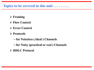
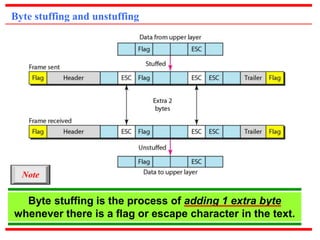
The data link layer needs to pack bits into frames,
so that each frame is distinguishable from another.
Our postal system practices a type of framing.
The simple act of inserting a letter into an envelope
separates one piece of information from another;
the envelope serves as the delimiter.
Topics discussed in this section:
a) Fixed-Size Framing
[ The size itself acts as delimiter or frame boundary ]
b) Variable-Size Framing
[ special character or bit pattern called flag is used as delimiter ]](https://image.slidesharecdn.com/unit2datalinkcontrol-140901094217-phpapp01/85/Unit-2-data-link-control-3-320.jpg)
![c) Flow Diagram [ for Simplest Protocol ]](https://image.slidesharecdn.com/unit2datalinkcontrol-140901094217-phpapp01/85/Unit-2-data-link-control-14-320.jpg)
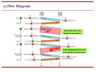
![c) Flow Diagram [ for Stop & Wait Protocol ]](https://image.slidesharecdn.com/unit2datalinkcontrol-140901094217-phpapp01/85/Unit-2-data-link-control-19-320.jpg)
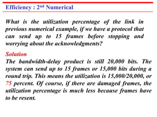

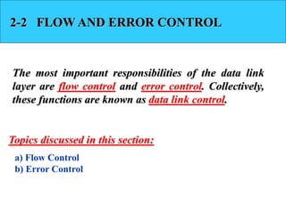
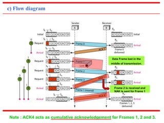
![c) Flow Diagram [ for Example 1 ]
Acknowledgement Frame-2 lost.
Note : ACK3 acts as cumulative acknowledgement for both Frames 1 & 2.](https://image.slidesharecdn.com/unit2datalinkcontrol-140901094217-phpapp01/85/Unit-2-data-link-control-41-320.jpg)
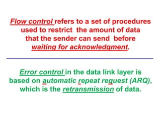
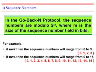
![Flow Diagram [ for Example 2 ]
Data Frame lost in the
middle of transmission.
Retransmission of
Frames 1, 2 and 3.](https://image.slidesharecdn.com/unit2datalinkcontrol-140901094217-phpapp01/85/Unit-2-data-link-control-42-320.jpg)
![11-6 HDLC
High-level Data Link Control (HDLC) is a bit-oriented
protocol for communication over point-to-point and
multipoint links. It implements the ARQ mechanisms
we discussed in this chapter.
Topics discussed in this section:
a) Configurations and Transfer Modes
~ Normal Response Mode [NRM]
~ Asynchronous Balanced Mode [ABM]
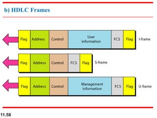
b) Frames
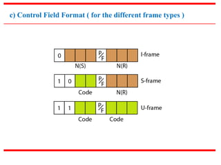
c) Control Field](https://image.slidesharecdn.com/unit2datalinkcontrol-140901094217-phpapp01/85/Unit-2-data-link-control-55-320.jpg)
![i) Normal Response Mode [ NRM ]](https://image.slidesharecdn.com/unit2datalinkcontrol-140901094217-phpapp01/85/Unit-2-data-link-control-56-320.jpg)
![ii) Asynchronous Balanced Mode [ ABM ]](https://image.slidesharecdn.com/unit2datalinkcontrol-140901094217-phpapp01/85/Unit-2-data-link-control-57-320.jpg)
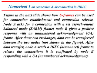
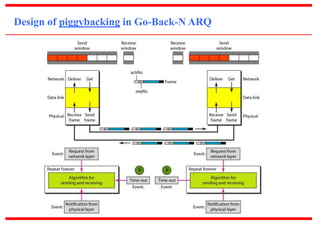
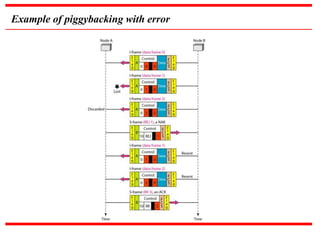
![Numerical 2 on piggybacking without error in HDLC
Figure in the next slide shows an exchange using piggybacking. Node
A begins the exchange of information with an I-frame numbered 0
followed by another I-frame numbered 1. Node B piggybacks its
acknowledgment of both frames onto an I-frame of its own. Node B’s
first I-frame is also numbered 0 [N(S) field] and contains a 2 in its
N(R) field, acknowledging the receipt of A’s frames 1 and 0 and
indicating that it expects frame 2 to arrive next. Node B transmits its
second and third I-frames (numbered 1 and 2) before accepting
further frames from node A. Its N(R) information, therefore, has not
changed: B frames 1 and 2 indicate that node B is still expecting A’s
frame 2 to arrive next. Node A has sent all its data. Therefore, it
cannot piggyback an acknowledgment onto an I-frame and sends an
S-frame instead. The RR code indicates that A is still ready to receive.
The number 3 in the N(R) field tells B that frames 0, 1, and 2 have all
been accepted and that A is now expecting frame number 3.](https://image.slidesharecdn.com/unit2datalinkcontrol-140901094217-phpapp01/85/Unit-2-data-link-control-63-320.jpg)

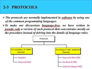
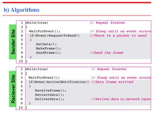
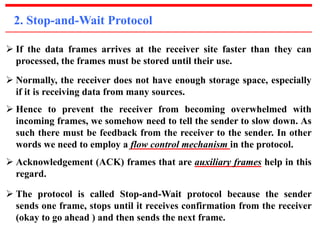
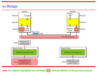
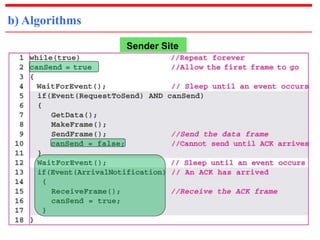
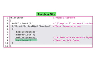
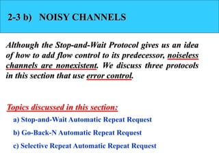
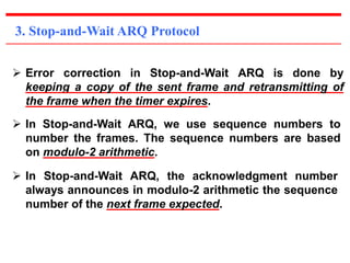
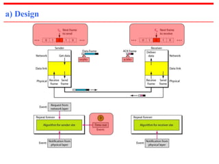
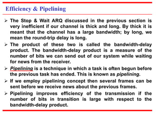
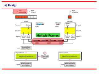
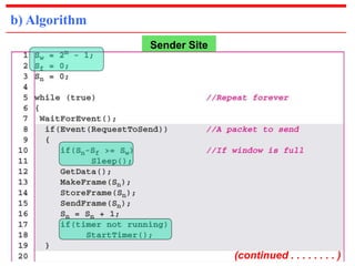
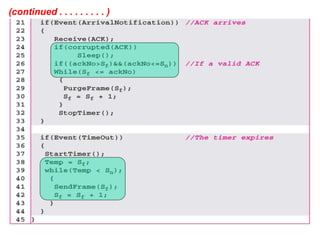
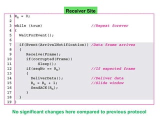
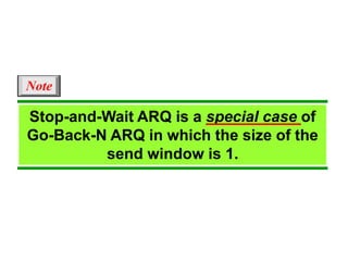
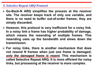
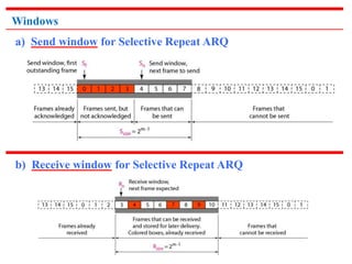
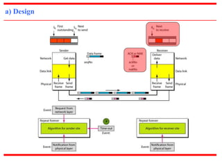
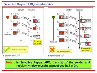
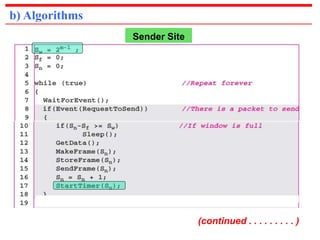
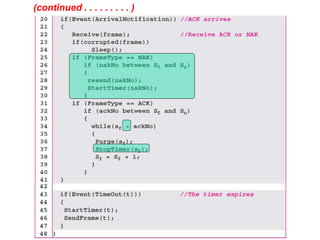
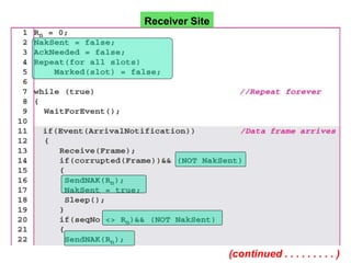
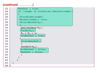
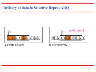
This document summarizes key topics related to data link control and protocols. It discusses framing methods like fixed-size and variable-size framing. It also covers flow control, error control, and protocols for both noiseless and noisy channels. Specific protocols described include the Simplest Protocol, Stop-and-Wait Protocol, Stop-and-Wait ARQ, Go-Back-N ARQ, and Selective Repeat ARQ. The document provides details on their design, algorithms, and flow diagrams to illustrate how each protocol handles framing, flow control, and error control.