Download as PDF, PPTX
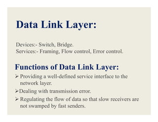
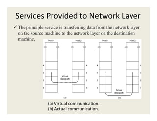
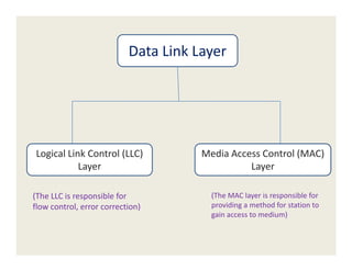
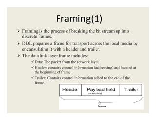
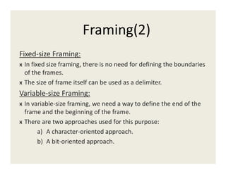
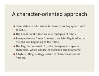
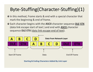
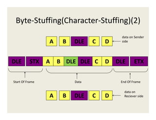
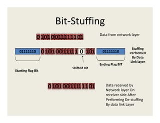


The document provides information about various data link layer concepts including: 1. The data link layer provides framing, flow control, and error control between network layers on different machines. It uses devices like switches and bridges. 2. Error detection methods include parity checks, checksums, and CRC to detect errors in transmitted frames. 3. Data link protocols for flow control include stop-and-wait, sliding window protocols, and ARQ methods like go-back-N and selective repeat. 4. Framing encapsulates data with headers and trailers using fixed or variable size frames. Methods like byte stuffing and bit stuffing handle special characters in the data.