Download as PDF, PPTX


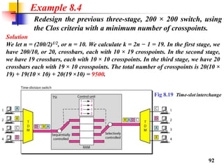
![Design a three-stage, 200 × 200 switch (N = 200) with k = 4 and n = 20.
Solution
In the first stage we have N/n or 10 crossbars, each of size 20 × 4. In the second
stage, we have 4 crossbars, each of size 10 × 10. In the third stage, we have 10
crossbars, each of size 4 × 20. The total number of crosspoints is 2kN + k(N/n)2,
or 2000 crosspoints. This is 5 percent of the number of crosspoints in a single-
stage switch (200 × 200 = 40,000).
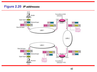
Example 8.3
In a three-stage switch, the total number of crosspoints is
2kN + k(N/n)2 which is much smaller than the number of crosspoints
in a single-stage switch (N2).
Note
According to the Clos criterion: n = (N/2)1/2
k > 2n – 1 Crosspoints ≥ 4N [(2N)1/2 – 1]
Note
91](https://image.slidesharecdn.com/cs8591u1-190424083031/85/Cs8591-Computer-Networks-91-320.jpg)


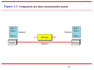
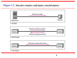
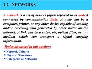
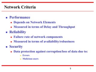
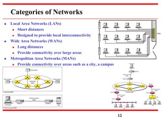
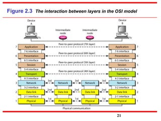
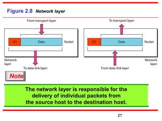
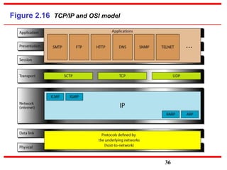
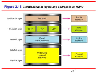
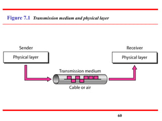
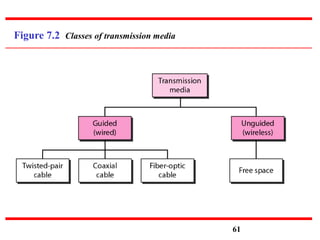
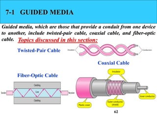
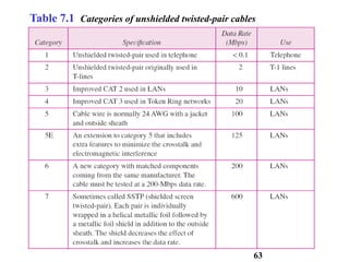
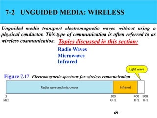
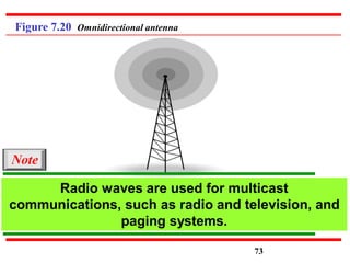
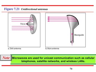
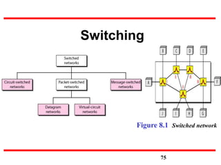
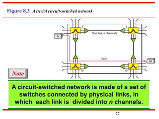
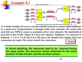
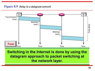
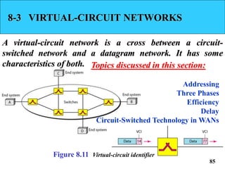
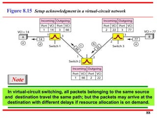
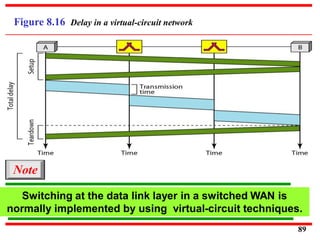
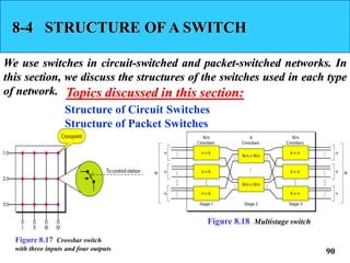
The document covers the fundamentals of computer networks, detailing the types of networks, data communication systems, and the OSI and TCP/IP models. It explores network criteria, performance metrics, and various forms of transmission media, both guided and unguided. Additionally, it discusses switching techniques, including circuit-switched and packet-switched networks, and their respective operations and characteristics.