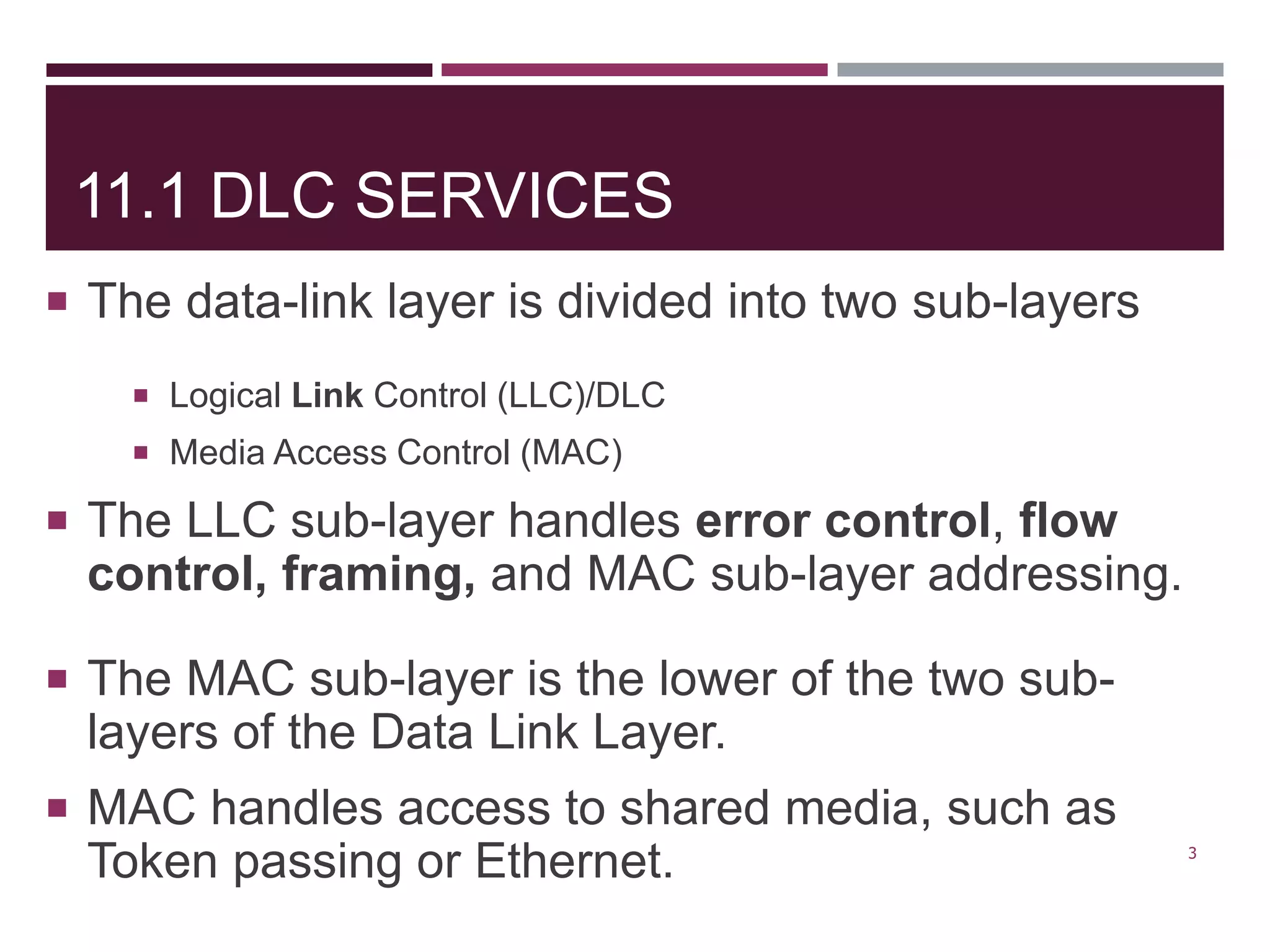
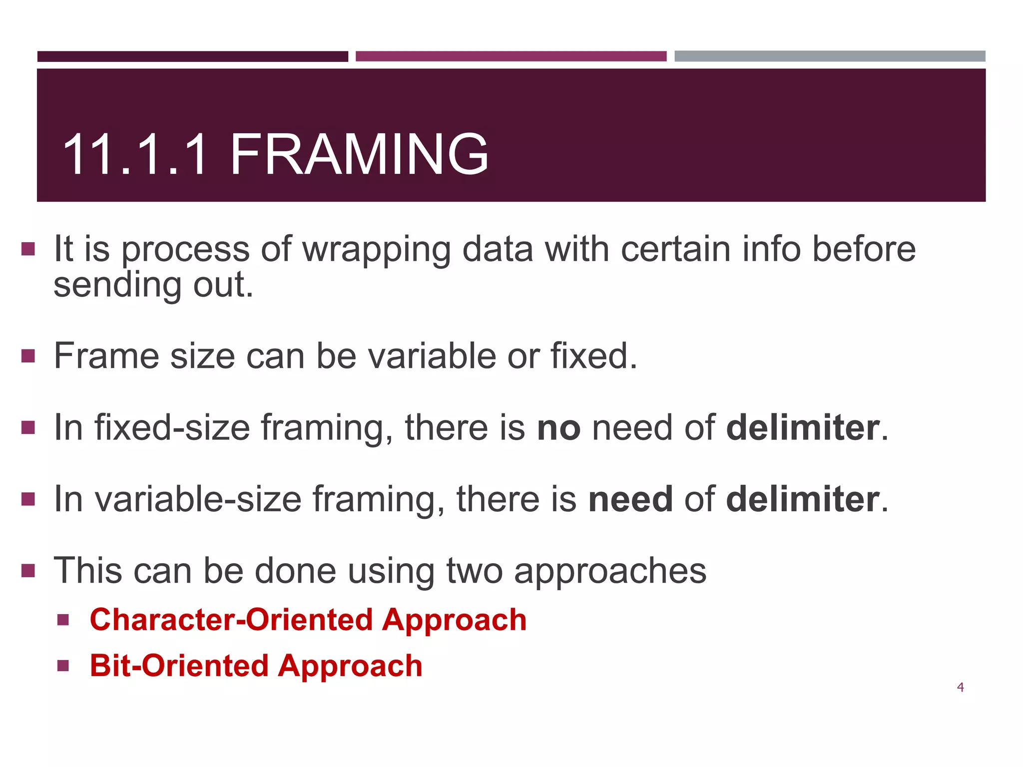
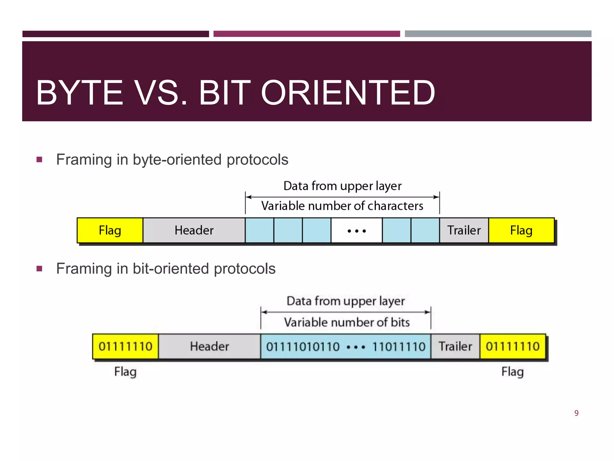
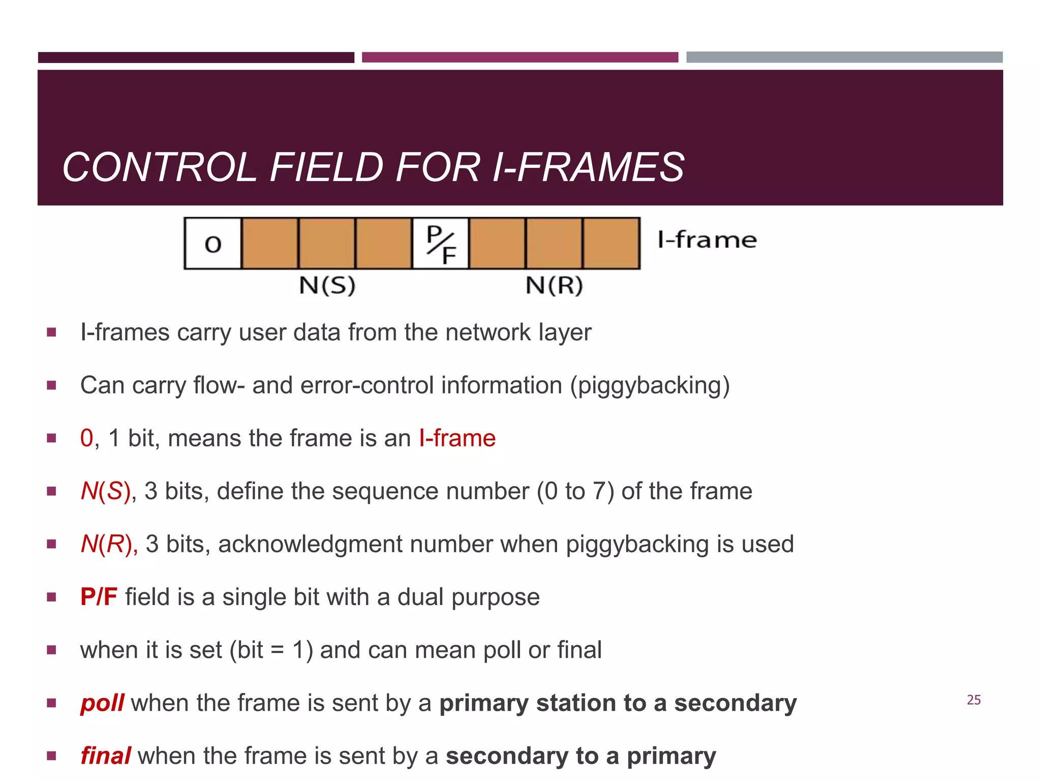
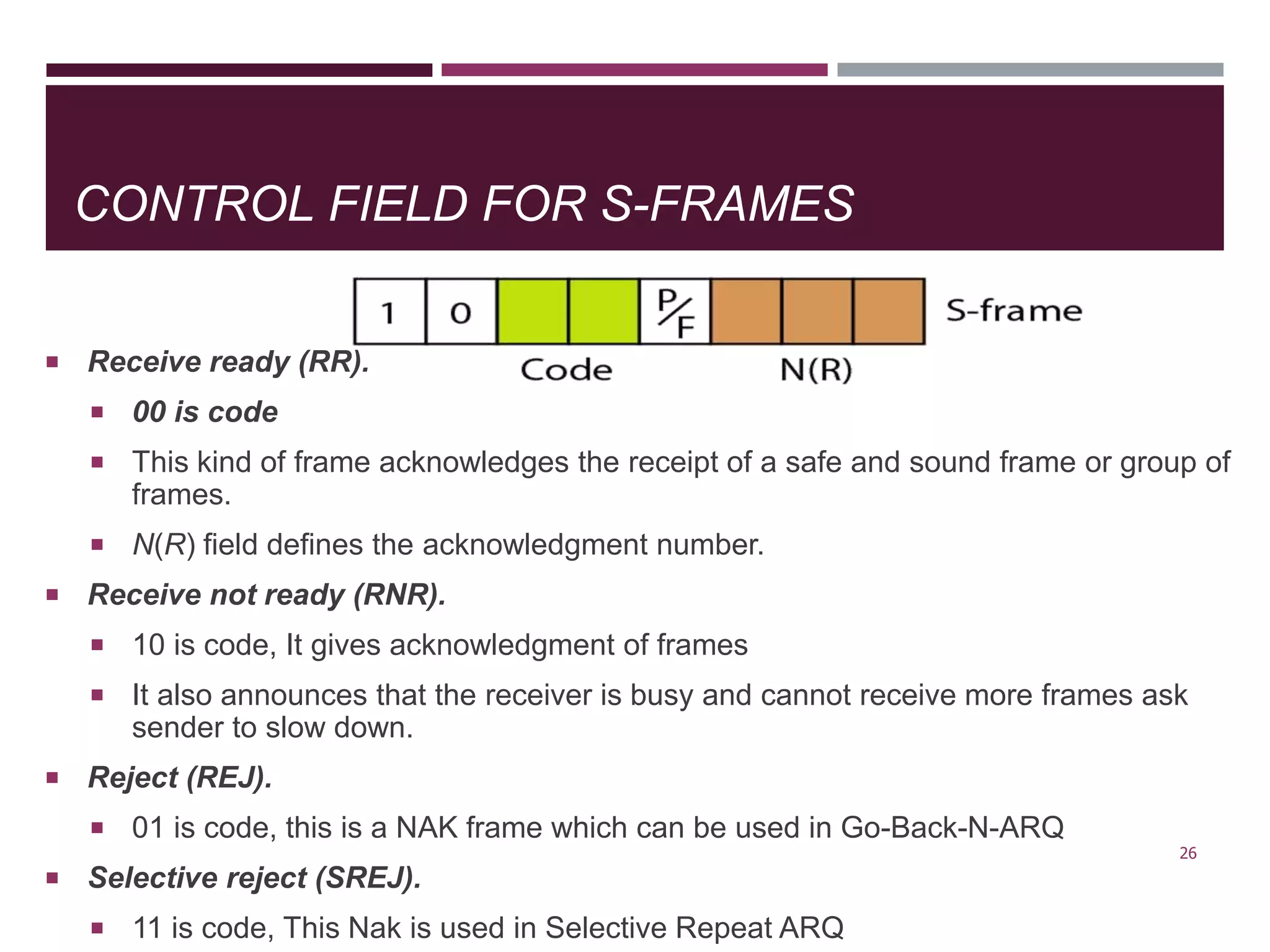
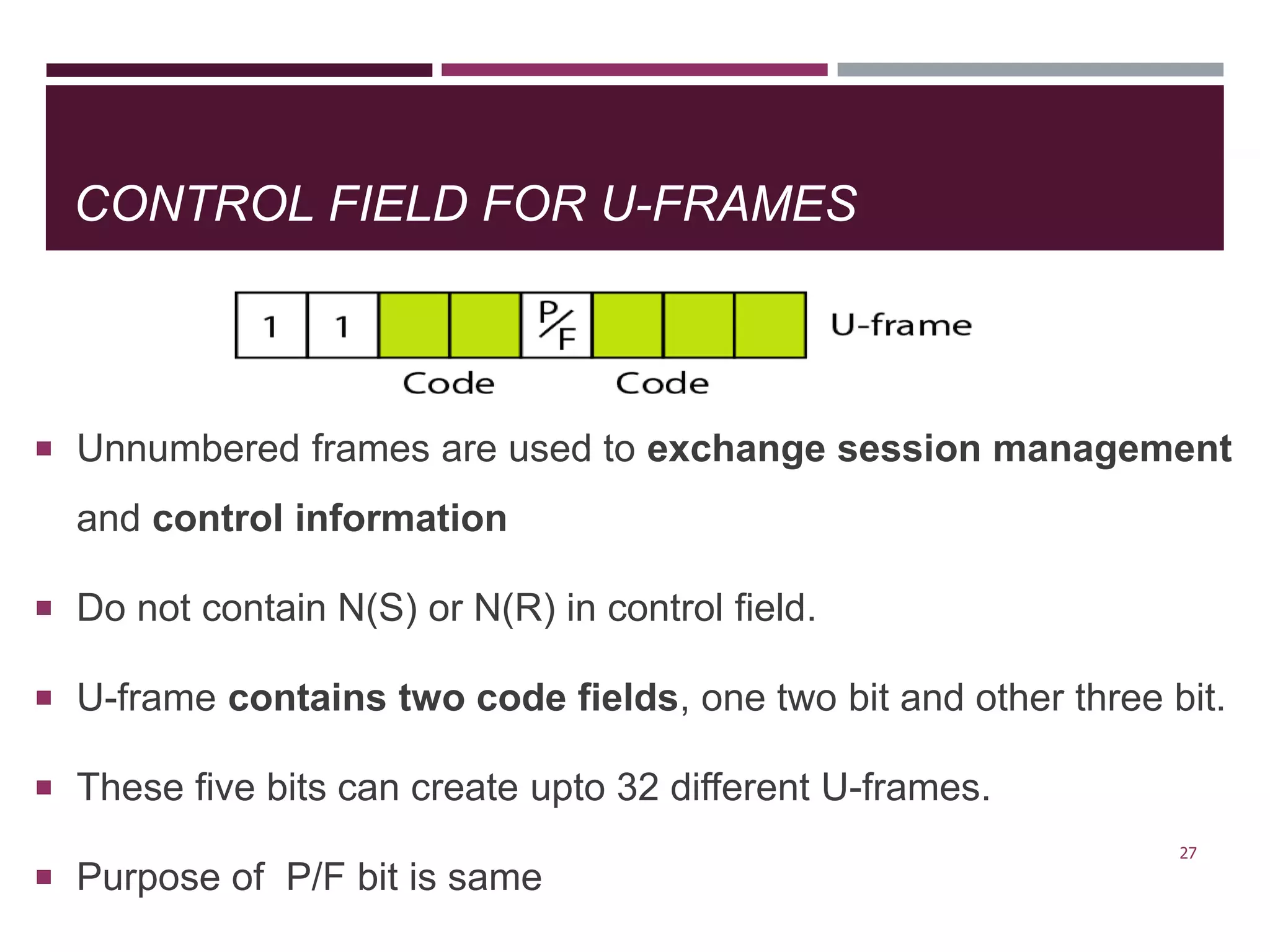
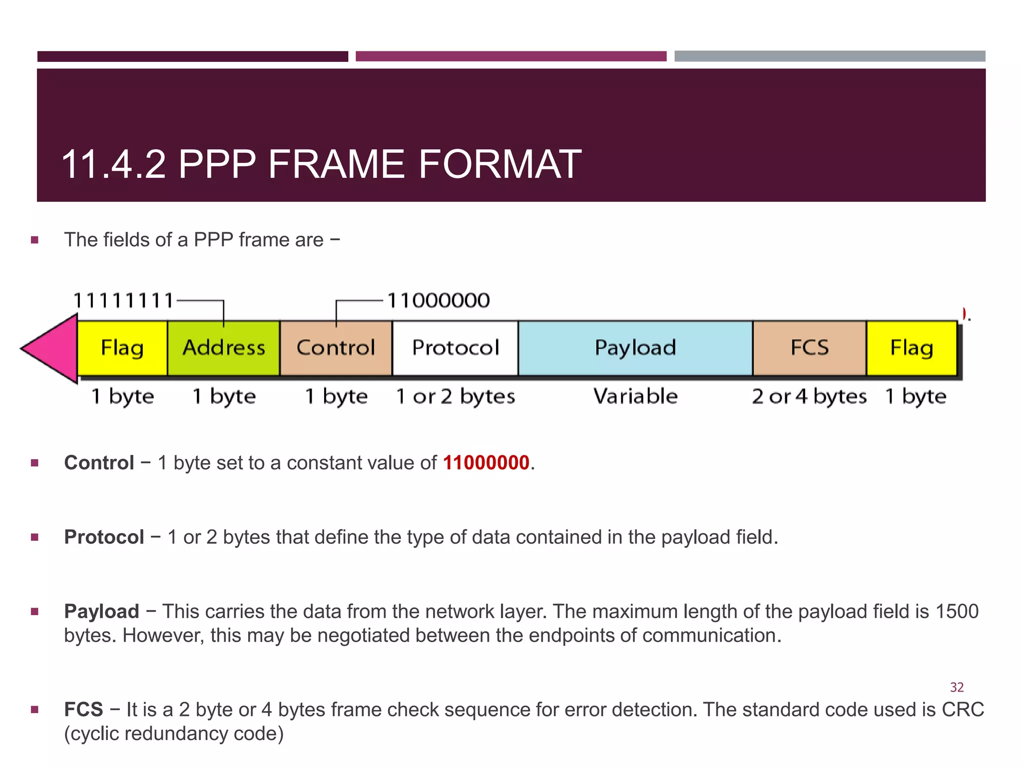
SlideShare a Scribd company logo
CH-11
DATA LINK LAYER:
DATA LINK CONTROL
- ASST. PROF. MEENAKSHI PAUL
G. N. KHALSA COLLEGE
OUTLINE
11.1 DLC SERVICES
11.1.1 Framing
11.1.2 Flow and Error Control
11.1.3 Connectionless and Connection-Oriented
11.2 DATA-LINK LAYER PROTOCOLS
11.2.1 Simple Protocol
11.2.2 Stop-and-Wait Protocol
11.2.3 Piggybacking
11.3 HDLC
11.3.1 Configurations and Transfer Modes
11.3.2 Framing
11.4 POINT-TO-POINT PROTOCOL (PPP)
11.4.1 Services
11.4.2 Framing
2
11.1 DLC SERVICES
 The data-link layer is divided into two sub-layers
 Logical Link Control (LLC)/DLC
 Media Access Control (MAC)
 The LLC sub-layer handles error control, flow
control, framing, and MAC sub-layer addressing.
 The MAC sub-layer is the lower of the two sub-
layers of the Data Link Layer.
 MAC handles access to shared media, such as
Token passing or Ethernet. 3
11.1.1 FRAMING
 It is process of wrapping data with certain info before
sending out.
 Frame size can be variable or fixed.
 In fixed-size framing, there is no need of delimiter.
 In variable-size framing, there is need of delimiter.
 This can be done using two approaches
 Character-Oriented Approach
 Bit-Oriented Approach
4
11.1.1 FRAMING
CONTD..
 Character-Oriented Framing(or Byte-Oriented):
 In COF framing, data carried 8-bit characters from a coding system
such as ASCII.
 A frame typically consists of
 Data from the upper layer
 Flag: indication for start and end of a frame, composed of special
characters (1-byte)
 Header: source/destination addresses, as well as other control
information
 Trailer: error detection/correction code
5
BYTE STUFFING
 Process of adding extra byte whenever there is an
escape or a flag character in the data
6
BIT-ORIENTED FRAMING
 In bit-oriented framing, data is transmitted as a
sequence of bits that can be interpreted in the upper
layers.
 Need a delimiter to separate one frame from the other.
 Each frame begins and ends with special bit pattern
called flag byte (01111110).
7
BIT STUFFING
 Process of adding extra bit to ensure flag sequence does not appear in the
data.
 When sender’s DLL finds 5 consecutive 1’s in data stream, stuffs 0.
 When receiver sees 5 1’s followed by 0, de-stuffs.
8
01111110
BYTE VS. BIT ORIENTED
 Framing in byte-oriented protocols
 Framing in bit-oriented protocols
9
FLOW CONTROL AND ERROR
CONTROL
 Flow control
 It is the process of managing the rate of data transmission
 It prevent a fast sender from overwhelming a slow
receiver.
 Error control
 It is the process of detecting and correcting data frames that
have been corrupted or lost during transmission.
 Retransmission of frames whenever error is detected or
frame is lost.
 Allows receiver to inform sender of lost or duplicate frames
10
11.1.3 CONNECTIONLESS AND CONNECTION-
ORIENTED
 A DLC protocol can be either connectionless
or connection-oriented.
 Connectionless Protocol
 No connection is established between two nodes.
 Each frame is independent.
 There is no connection between frames.
 Frames are not numbered
 Connection-Oriented Protocol
 A logical connection must be established between the two nodes( setup,
data transfer and teardown)
 The frames are numbered and sent in order
11
11.2 DATA-LINK LAYER PROTOCOLS
 Data link layer have four protocols
 Simple,
 Stop-and-Wait,
 Go-Back-N, and
 Selective-Repeat that deal with flow and error control
 First two protocols still are used at the data-link
layer
12
11.2.1 SIMPLE PROTOCOL
 A simple protocol with neither flow nor error control.
 We assume that the receiver can immediately handle any frame it receives.
 The receiver can never be overwhelmed with incoming frames.
 The DLL sender gets a packet from its network layer, makes a frame out of it, and
sends the frame.
 The DLL at the receiver receives a frame from the link, extracts the packet from the
frame, and delivers the packet to its network layer.
 The data-link layers of the sender and receiver provide transmission services for their
network layers.
13
FLOW DIAGRAM SIMPLE PROTOCOL
 It is very simple.
 The sender sends frames one after another without even
thinking about the receiver.
14
11.2.2 STOP-AND-WAIT
PROTOCOL
 It uses both flow and error control.
 The sender will send one frame at a time.
 The sender will stop and wait for the acknowledgment (ACK) from the
receiver.
 After receiving ACK sender send the next packet to receiver.
 Receiver responds with an ACK when it successfully receives a frame
 Both Data and ACK frames must be numbered
 When sender does not receive an ack within certain time, it assumes
frame is lost, then retransmits the same frame.
15
11.2.2 STOP-AND-WAIT
PROTOCOL
16
11.2.3 PIGGYBACKING
 Piggybacking is the process of converting two
way process to one way process.
 In this sender send both (Data+ACK) to the
receiver.
 Data and acknowledgement are send in a single
frame is called Piggybacking.
 Piggybacking saves bandwidth.
17
11.2.3 PIGGYBACKING
18
11.3 HDLC
 High-level Data Link Control
 Bit-oriented protocol
 Support both
 Point-to-point links
 Multipoint links
 It implements the Stop-and-Wait protocol
 HDLC provides two common transfer modes
 Normal Response Mode (NRM)
 Asynchronous Balanced Mode (ABM)
19
NORMAL RESPONSE MODE
(NRM)
 In NRM, the configuration is unbalanced.
 Have one primary station and multiple secondary stations.
 A primary station can send commands; a secondary station can only
respond.
 Used in both point-to-point and multi-point link
20
ASYNCHRONOUS BALANCE MODE (ABM)
 In ABM, the configuration is balanced
 Supports only point-to-point links
 Each station is both primary and secondary
21
11.3.2 HDLC FRAMES
 HDLC defines three types of frames:
 Information frames (I-frames)
 Supervisory frames (S-frames)
 Unnumbered frames (U-frames)
 I-frames are used to data-link user data and control information relating to user data
(piggybacking).
 S-frames are used only to transport control information.
 U-frames are reserved for system management. Information carried by U-frames is
intended for managing the link itself. 22
11.3.2 HDLC FRAMES
 HDLC frame may contain up to six fields
 A beginning flag field, an address field, a control field, an information field, a
frame check sequence (FCS) field, and an ending flag field.
Information frame (I-frame)
Supervisory frame (S-frame)
Unnumbered frame (U-frame)
23
Frame Check Sequence
(error detection code)
11.3.2 HDLC FRAMES
Flag field.
 This field contains synchronization pattern 01111110, which identifies both the beginning and the end of
a frame.
Address field.
 This field contains the address of the secondary station.
 If a primary station created the frame, it contains a to address.
 If a secondary station creates the frame, it contains a from address.
 The address field can be one byte or several bytes long, depending on the needs of the network.
Control field.
 The control field is one or two bytes used for flow and error control.
Information field.
 The information field contains the user’s data from the network layer or management information.
 Its length can vary from one network to another.
FCS field.
 The frame check sequence (FCS) is the HDLC error detection field.
 It can contain either a 2- or 4-byte CRC.
24
CONTROL FIELD FOR I-FRAMES
 I-frames carry user data from the network layer
 Can carry flow- and error-control information (piggybacking)
 0, 1 bit, means the frame is an I-frame
 N(S), 3 bits, define the sequence number (0 to 7) of the frame
 N(R), 3 bits, acknowledgment number when piggybacking is used
 P/F field is a single bit with a dual purpose
 when it is set (bit = 1) and can mean poll or final
 poll when the frame is sent by a primary station to a secondary
 final when the frame is sent by a secondary to a primary
25
CONTROL FIELD FOR S-FRAMES
 Receive ready (RR).
 00 is code
 This kind of frame acknowledges the receipt of a safe and sound frame or group of
frames.
 N(R) field defines the acknowledgment number.
 Receive not ready (RNR).
 10 is code, It gives acknowledgment of frames
 It also announces that the receiver is busy and cannot receive more frames ask
sender to slow down.
 Reject (REJ).
 01 is code, this is a NAK frame which can be used in Go-Back-N-ARQ
 Selective reject (SREJ).
 11 is code, This Nak is used in Selective Repeat ARQ
26
CONTROL FIELD FOR U-FRAMES
 Unnumbered frames are used to exchange session management
and control information
 Do not contain N(S) or N(R) in control field.
 U-frame contains two code fields, one two bit and other three bit.
 These five bits can create upto 32 different U-frames.
 Purpose of P/F bit is same
27
U-FRAME CODES
28
11.4 POINT-TO-POINT PROTOCOL (PPP)
 Point-to-Point Protocol
 Byte-oriented protocol
 Most common protocol for point-to-point access
 Dial-up access
 ADSL (Asymmetric Digital Subscriber Line)
29
11.4.1 SERVICES PROVIDED BY PPP
 Defining the frame format of the data to be transmitted.
 Defining the procedure of establishing link between two points and
exchange of data.
 Stating the method of encapsulation of network layer data in the frame.
 Stating authentication rules of the communicating devices.
 Providing address for network communication.
 Providing connections over multiple links.
 Supporting a variety of network layer protocols by providing a range os
services.
30
11.4.1 SERVICES NOT PROVIDED BY PPP
 PPP does not provide flow control
 A sender send frames one after another without concern of receiver.
 PPP has a very simple mechanism for error control.
 A CRC field is used to detect errors.
 If the frame is corrupted, it is silently discarded; the upper-layer protocol needs to
take care of the problem.
 Lack of error control and sequence numbering may cause a packet to be received
out of order.
 PPP does not provide a sophisticated addressing mechanism to handle frames in
a multipoint configuration.
31
11.4.2 PPP FRAME FORMAT
 The fields of a PPP frame are −
 Flag − 1 byte that marks the beginning and the end of the frame. The bit pattern of the flag is 01111110.
 Address − 1 byte which is set to 11111111 in case of broadcast.
 Control − 1 byte set to a constant value of 11000000.
 Protocol − 1 or 2 bytes that define the type of data contained in the payload field.
 Payload − This carries the data from the network layer. The maximum length of the payload field is 1500
bytes. However, this may be negotiated between the endpoints of communication.
 FCS − It is a 2 byte or 4 bytes frame check sequence for error detection. The standard code used is CRC
(cyclic redundancy code)
32

More Related Content

What's hot

TCP/IP Protocols With All Layer Description
TCP/IP Protocols With All Layer DescriptionTCP/IP Protocols With All Layer Description
TCP/IP Protocols With All Layer Description
Shubham Khedekar
 
Error Detection And Correction
Error Detection And CorrectionError Detection And Correction
Error Detection And Correction
Renu Kewalramani
 
User datagram protocol (udp)
User datagram protocol (udp)User datagram protocol (udp)
User datagram protocol (udp)
Ramola Dhande
 
Chapter 2 - Network Models
Chapter 2 - Network ModelsChapter 2 - Network Models
Chapter 2 - Network ModelsWayne Jones Jnr
 
DATA RATE LIMITS
DATA RATE LIMITSDATA RATE LIMITS
DATA RATE LIMITS
ChAwais15
 
TCP/ IP
TCP/ IP TCP/ IP
Block coding, error detection (Parity checking, Cyclic redundancy checking (C...
Block coding, error detection (Parity checking, Cyclic redundancy checking (C...Block coding, error detection (Parity checking, Cyclic redundancy checking (C...
Block coding, error detection (Parity checking, Cyclic redundancy checking (C...
Paulo_Vangui
 
Token bus
Token busToken bus
Token bus
Denver Rockfreak
 
Unit 2 data link control
Unit 2 data link controlUnit 2 data link control
Unit 2 data link control
Vishal kakade
 
Go back-n protocol
Go back-n protocolGo back-n protocol
Go back-n protocol
STEFFY D
 
Sliding window protocol
Sliding window protocolSliding window protocol
Sliding window protocol
Shehara Abeythunga
 
Computer network switching
Computer network switchingComputer network switching
Computer network switching
Shivani Godha
 
Packet switching
Packet switchingPacket switching
Packet switchingasimnawaz54
 
TCP and UDP
TCP and UDP TCP and UDP
TCP and UDP
Ramesh Giri
 
data-link layer protocols
data-link layer protocols  data-link layer protocols
data-link layer protocols
BE Smârt
 
Transport layer
Transport layer Transport layer
Transport layer
Mukesh Chinta
 
Data link layer
Data link layer Data link layer
Data link layer
Mukesh Chinta
 
CS6551 COMPUTER NETWORKS
CS6551 COMPUTER NETWORKSCS6551 COMPUTER NETWORKS
CS6551 COMPUTER NETWORKS
Kathirvel Ayyaswamy
 

What's hot (20)

Mac layer
Mac  layerMac  layer
Mac layer
 
TCP/IP Protocols With All Layer Description
TCP/IP Protocols With All Layer DescriptionTCP/IP Protocols With All Layer Description
TCP/IP Protocols With All Layer Description
 
Error Detection And Correction
Error Detection And CorrectionError Detection And Correction
Error Detection And Correction
 
User datagram protocol (udp)
User datagram protocol (udp)User datagram protocol (udp)
User datagram protocol (udp)
 
Chapter 2 - Network Models
Chapter 2 - Network ModelsChapter 2 - Network Models
Chapter 2 - Network Models
 
DATA RATE LIMITS
DATA RATE LIMITSDATA RATE LIMITS
DATA RATE LIMITS
 
TCP/ IP
TCP/ IP TCP/ IP
TCP/ IP
 
Block coding, error detection (Parity checking, Cyclic redundancy checking (C...
Block coding, error detection (Parity checking, Cyclic redundancy checking (C...Block coding, error detection (Parity checking, Cyclic redundancy checking (C...
Block coding, error detection (Parity checking, Cyclic redundancy checking (C...
 
Token bus
Token busToken bus
Token bus
 
Unit 2 data link control
Unit 2 data link controlUnit 2 data link control
Unit 2 data link control
 
Go back-n protocol
Go back-n protocolGo back-n protocol
Go back-n protocol
 
Sliding window protocol
Sliding window protocolSliding window protocol
Sliding window protocol
 
Computer network switching
Computer network switchingComputer network switching
Computer network switching
 
Circuit Switching
Circuit SwitchingCircuit Switching
Circuit Switching
 
Packet switching
Packet switchingPacket switching
Packet switching
 
TCP and UDP
TCP and UDP TCP and UDP
TCP and UDP
 
data-link layer protocols
data-link layer protocols  data-link layer protocols
data-link layer protocols
 
Transport layer
Transport layer Transport layer
Transport layer
 
Data link layer
Data link layer Data link layer
Data link layer
 
CS6551 COMPUTER NETWORKS
CS6551 COMPUTER NETWORKSCS6551 COMPUTER NETWORKS
CS6551 COMPUTER NETWORKS
 

Similar to Data Link Control

Data link control & protocol concepts
Data link control & protocol conceptsData link control & protocol concepts
Data link control & protocol concepts
Raji Lakshmi
 
unit2-210710110327.pdf
unit2-210710110327.pdfunit2-210710110327.pdf
unit2-210710110327.pdf
ssuser3aa461
 
HDLC, PPP and SLIP
HDLC, PPP and SLIPHDLC, PPP and SLIP
HDLC, PPP and SLIP
Naveen Kumar
 
High level data link control
High level data link controlHigh level data link control
High level data link control
KarthigaGunasekaran1
 
High speed Networking
High speed NetworkingHigh speed Networking
High speed Networking
sdb2002
 
HDLC
HDLCHDLC
DLL
DLLDLL
HDLC-Protocol-Overview-Presentation.pdf
HDLC-Protocol-Overview-Presentation.pdfHDLC-Protocol-Overview-Presentation.pdf
HDLC-Protocol-Overview-Presentation.pdf
2O550Sujal
 
Unit 3 - Data Link Layer - Part A
Unit 3 - Data Link Layer - Part AUnit 3 - Data Link Layer - Part A
Unit 3 - Data Link Layer - Part A
Chandan Gupta Bhagat
 
datalinklayermukesh
datalinklayermukeshdatalinklayermukesh
datalinklayermukesh
TamiratDejene1
 
U2CH1Data Link Layerxxxxxxxxxxxxxxxxx.pptx
U2CH1Data Link Layerxxxxxxxxxxxxxxxxx.pptxU2CH1Data Link Layerxxxxxxxxxxxxxxxxx.pptx
U2CH1Data Link Layerxxxxxxxxxxxxxxxxx.pptx
k2w9psdb96
 
CN UNIT II.pptx
CN UNIT II.pptxCN UNIT II.pptx
CN UNIT II.pptx
VISWANATHAN R V
 
Hdlc
HdlcHdlc
HDLC(High level Data Link Control)
HDLC(High level Data Link Control)HDLC(High level Data Link Control)
HDLC(High level Data Link Control)
sonangrai
 
Unit 2
Unit 2Unit 2
Unit 2
APARNA P
 
Module 5 high speed swan,atm,transport layer
Module 5 high speed swan,atm,transport layerModule 5 high speed swan,atm,transport layer
Module 5 high speed swan,atm,transport layer
Deepak John
 
Module 4 netwok layer,routing ,vlan,x.25doc
Module 4 netwok layer,routing ,vlan,x.25docModule 4 netwok layer,routing ,vlan,x.25doc
Module 4 netwok layer,routing ,vlan,x.25doc
Deepak John
 
DATA LINK CONTROL.pptx
DATA LINK CONTROL.pptxDATA LINK CONTROL.pptx
DATA LINK CONTROL.pptx
ODINARARCH
 

Similar to Data Link Control (20)

Data link control & protocol concepts
Data link control & protocol conceptsData link control & protocol concepts
Data link control & protocol concepts
 
unit2-210710110327.pdf
unit2-210710110327.pdfunit2-210710110327.pdf
unit2-210710110327.pdf
 
HDLC, PPP and SLIP
HDLC, PPP and SLIPHDLC, PPP and SLIP
HDLC, PPP and SLIP
 
Hdlc
HdlcHdlc
Hdlc
 
High level data link control
High level data link controlHigh level data link control
High level data link control
 
High speed Networking
High speed NetworkingHigh speed Networking
High speed Networking
 
HDLC
HDLCHDLC
HDLC
 
Hdlc
HdlcHdlc
Hdlc
 
DLL
DLLDLL
DLL
 
HDLC-Protocol-Overview-Presentation.pdf
HDLC-Protocol-Overview-Presentation.pdfHDLC-Protocol-Overview-Presentation.pdf
HDLC-Protocol-Overview-Presentation.pdf
 
Unit 3 - Data Link Layer - Part A
Unit 3 - Data Link Layer - Part AUnit 3 - Data Link Layer - Part A
Unit 3 - Data Link Layer - Part A
 
datalinklayermukesh
datalinklayermukeshdatalinklayermukesh
datalinklayermukesh
 
U2CH1Data Link Layerxxxxxxxxxxxxxxxxx.pptx
U2CH1Data Link Layerxxxxxxxxxxxxxxxxx.pptxU2CH1Data Link Layerxxxxxxxxxxxxxxxxx.pptx
U2CH1Data Link Layerxxxxxxxxxxxxxxxxx.pptx
 
CN UNIT II.pptx
CN UNIT II.pptxCN UNIT II.pptx
CN UNIT II.pptx
 
Hdlc
HdlcHdlc
Hdlc
 
HDLC(High level Data Link Control)
HDLC(High level Data Link Control)HDLC(High level Data Link Control)
HDLC(High level Data Link Control)
 
Unit 2
Unit 2Unit 2
Unit 2
 
Module 5 high speed swan,atm,transport layer
Module 5 high speed swan,atm,transport layerModule 5 high speed swan,atm,transport layer
Module 5 high speed swan,atm,transport layer
 
Module 4 netwok layer,routing ,vlan,x.25doc
Module 4 netwok layer,routing ,vlan,x.25docModule 4 netwok layer,routing ,vlan,x.25doc
Module 4 netwok layer,routing ,vlan,x.25doc
 
DATA LINK CONTROL.pptx
DATA LINK CONTROL.pptxDATA LINK CONTROL.pptx
DATA LINK CONTROL.pptx
 

More from Meenakshi Paul

Introduction to Artificial Intelligences
Introduction to Artificial IntelligencesIntroduction to Artificial Intelligences
Introduction to Artificial Intelligences
Meenakshi Paul
 
Binary Arithmetic
Binary ArithmeticBinary Arithmetic
Binary Arithmetic
Meenakshi Paul
 
19 Network Layer Protocols
19 Network Layer Protocols19 Network Layer Protocols
19 Network Layer Protocols
Meenakshi Paul
 
Other Wireless Networks
Other Wireless NetworksOther Wireless Networks
Other Wireless Networks
Meenakshi Paul
 
Wireless LANs
Wireless LANsWireless LANs
Wireless LANs
Meenakshi Paul
 
Wired LANs
Wired LANsWired LANs
Wired LANs
Meenakshi Paul
 
Codes
CodesCodes
Number System
Number SystemNumber System
Number System
Meenakshi Paul
 
Media Access Control (MAC Layer)
Media Access Control (MAC Layer)Media Access Control (MAC Layer)
Media Access Control (MAC Layer)
Meenakshi Paul
 
Introduction to the Data Link Layer
Introduction to the Data Link LayerIntroduction to the Data Link Layer
Introduction to the Data Link Layer
Meenakshi Paul
 
Switching
SwitchingSwitching
Switching
Meenakshi Paul
 
Transmission Media
Transmission MediaTransmission Media
Transmission Media
Meenakshi Paul
 
Bandwidth Utilization Multiplexing and Spectrum Spreading
Bandwidth Utilization Multiplexing and Spectrum SpreadingBandwidth Utilization Multiplexing and Spectrum Spreading
Bandwidth Utilization Multiplexing and Spectrum Spreading
Meenakshi Paul
 
IP classes
IP classesIP classes
IP classes
Meenakshi Paul
 
Theory building
Theory buildingTheory building
Theory building
Meenakshi Paul
 
Information Systems and Knowledge Management
 Information Systems and Knowledge Management Information Systems and Knowledge Management
Information Systems and Knowledge Management
Meenakshi Paul
 
Ch01 The Role of Business Research
Ch01 The Role of Business ResearchCh01 The Role of Business Research
Ch01 The Role of Business Research
Meenakshi Paul
 
05 analog transmission
05 analog transmission05 analog transmission
05 analog transmission
Meenakshi Paul
 
04 digital transmission
04 digital transmission04 digital transmission
04 digital transmission
Meenakshi Paul
 
03 Introduction to Physical layer
03  Introduction to Physical layer03  Introduction to Physical layer
03 Introduction to Physical layer
Meenakshi Paul
 

More from Meenakshi Paul (20)

Introduction to Artificial Intelligences
Introduction to Artificial IntelligencesIntroduction to Artificial Intelligences
Introduction to Artificial Intelligences
 
Binary Arithmetic
Binary ArithmeticBinary Arithmetic
Binary Arithmetic
 
19 Network Layer Protocols
19 Network Layer Protocols19 Network Layer Protocols
19 Network Layer Protocols
 
Other Wireless Networks
Other Wireless NetworksOther Wireless Networks
Other Wireless Networks
 
Wireless LANs
Wireless LANsWireless LANs
Wireless LANs
 
Wired LANs
Wired LANsWired LANs
Wired LANs
 
Codes
CodesCodes
Codes
 
Number System
Number SystemNumber System
Number System
 
Media Access Control (MAC Layer)
Media Access Control (MAC Layer)Media Access Control (MAC Layer)
Media Access Control (MAC Layer)
 
Introduction to the Data Link Layer
Introduction to the Data Link LayerIntroduction to the Data Link Layer
Introduction to the Data Link Layer
 
Switching
SwitchingSwitching
Switching
 
Transmission Media
Transmission MediaTransmission Media
Transmission Media
 
Bandwidth Utilization Multiplexing and Spectrum Spreading
Bandwidth Utilization Multiplexing and Spectrum SpreadingBandwidth Utilization Multiplexing and Spectrum Spreading
Bandwidth Utilization Multiplexing and Spectrum Spreading
 
IP classes
IP classesIP classes
IP classes
 
Theory building
Theory buildingTheory building
Theory building
 
Information Systems and Knowledge Management
 Information Systems and Knowledge Management Information Systems and Knowledge Management
Information Systems and Knowledge Management
 
Ch01 The Role of Business Research
Ch01 The Role of Business ResearchCh01 The Role of Business Research
Ch01 The Role of Business Research
 
05 analog transmission
05 analog transmission05 analog transmission
05 analog transmission
 
04 digital transmission
04 digital transmission04 digital transmission
04 digital transmission
 
03 Introduction to Physical layer
03  Introduction to Physical layer03  Introduction to Physical layer
03 Introduction to Physical layer
 

Recently uploaded

ethical hacking in wireless-hacking1.ppt
ethical hacking in wireless-hacking1.pptethical hacking in wireless-hacking1.ppt
ethical hacking in wireless-hacking1.ppt
Jayaprasanna4
 
Planning Of Procurement o different goods and services
Planning Of Procurement o different goods and servicesPlanning Of Procurement o different goods and services
Planning Of Procurement o different goods and services
JoytuBarua2
 
The role of big data in decision making.
The role of big data in decision making.The role of big data in decision making.
The role of big data in decision making.
ankuprajapati0525
 
H.Seo, ICLR 2024, MLILAB, KAIST AI.pdf
H.Seo,  ICLR 2024, MLILAB,  KAIST AI.pdfH.Seo,  ICLR 2024, MLILAB,  KAIST AI.pdf
H.Seo, ICLR 2024, MLILAB, KAIST AI.pdf
MLILAB
 
J.Yang, ICLR 2024, MLILAB, KAIST AI.pdf
J.Yang,  ICLR 2024, MLILAB, KAIST AI.pdfJ.Yang,  ICLR 2024, MLILAB, KAIST AI.pdf
J.Yang, ICLR 2024, MLILAB, KAIST AI.pdf
MLILAB
 
Nuclear Power Economics and Structuring 2024
Nuclear Power Economics and Structuring 2024Nuclear Power Economics and Structuring 2024
Nuclear Power Economics and Structuring 2024
Massimo Talia
 
Forklift Classes Overview by Intella Parts
Forklift Classes Overview by Intella PartsForklift Classes Overview by Intella Parts
Forklift Classes Overview by Intella Parts
Intella Parts
 
Top 10 Oil and Gas Projects in Saudi Arabia 2024.pdf
Top 10 Oil and Gas Projects in Saudi Arabia 2024.pdfTop 10 Oil and Gas Projects in Saudi Arabia 2024.pdf
Top 10 Oil and Gas Projects in Saudi Arabia 2024.pdf
Teleport Manpower Consultant
 
Cosmetic shop management system project report.pdf
Cosmetic shop management system project report.pdfCosmetic shop management system project report.pdf
Cosmetic shop management system project report.pdf
Kamal Acharya
 
CFD Simulation of By-pass Flow in a HRSG module by R&R Consult.pptx
CFD Simulation of By-pass Flow in a HRSG module by R&R Consult.pptxCFD Simulation of By-pass Flow in a HRSG module by R&R Consult.pptx
CFD Simulation of By-pass Flow in a HRSG module by R&R Consult.pptx
R&R Consult
 
Student information management system project report ii.pdf
Student information management system project report ii.pdfStudent information management system project report ii.pdf
Student information management system project report ii.pdf
Kamal Acharya
 
Event Management System Vb Net Project Report.pdf
Event Management System Vb Net  Project Report.pdfEvent Management System Vb Net  Project Report.pdf
Event Management System Vb Net Project Report.pdf
Kamal Acharya
 
Sachpazis:Terzaghi Bearing Capacity Estimation in simple terms with Calculati...
Sachpazis:Terzaghi Bearing Capacity Estimation in simple terms with Calculati...Sachpazis:Terzaghi Bearing Capacity Estimation in simple terms with Calculati...
Sachpazis:Terzaghi Bearing Capacity Estimation in simple terms with Calculati...
Dr.Costas Sachpazis
 
Final project report on grocery store management system..pdf
Final project report on grocery store management system..pdfFinal project report on grocery store management system..pdf
Final project report on grocery store management system..pdf
Kamal Acharya
 
power quality voltage fluctuation UNIT - I.pptx
power quality voltage fluctuation UNIT - I.pptxpower quality voltage fluctuation UNIT - I.pptx
power quality voltage fluctuation UNIT - I.pptx
ViniHema
 
TECHNICAL TRAINING MANUAL GENERAL FAMILIARIZATION COURSE
TECHNICAL TRAINING MANUAL   GENERAL FAMILIARIZATION COURSETECHNICAL TRAINING MANUAL   GENERAL FAMILIARIZATION COURSE
TECHNICAL TRAINING MANUAL GENERAL FAMILIARIZATION COURSE
DuvanRamosGarzon1
 
Quality defects in TMT Bars, Possible causes and Potential Solutions.
Quality defects in TMT Bars, Possible causes and Potential Solutions.Quality defects in TMT Bars, Possible causes and Potential Solutions.
Quality defects in TMT Bars, Possible causes and Potential Solutions.
PrashantGoswami42
 
Design and Analysis of Algorithms-DP,Backtracking,Graphs,B&B
Design and Analysis of Algorithms-DP,Backtracking,Graphs,B&BDesign and Analysis of Algorithms-DP,Backtracking,Graphs,B&B
Design and Analysis of Algorithms-DP,Backtracking,Graphs,B&B
Sreedhar Chowdam
 
COLLEGE BUS MANAGEMENT SYSTEM PROJECT REPORT.pdf
COLLEGE BUS MANAGEMENT SYSTEM PROJECT REPORT.pdfCOLLEGE BUS MANAGEMENT SYSTEM PROJECT REPORT.pdf
COLLEGE BUS MANAGEMENT SYSTEM PROJECT REPORT.pdf
Kamal Acharya
 
WATER CRISIS and its solutions-pptx 1234
WATER CRISIS and its solutions-pptx 1234WATER CRISIS and its solutions-pptx 1234
WATER CRISIS and its solutions-pptx 1234
AafreenAbuthahir2
 

Recently uploaded (20)

ethical hacking in wireless-hacking1.ppt
ethical hacking in wireless-hacking1.pptethical hacking in wireless-hacking1.ppt
ethical hacking in wireless-hacking1.ppt
 
Planning Of Procurement o different goods and services
Planning Of Procurement o different goods and servicesPlanning Of Procurement o different goods and services
Planning Of Procurement o different goods and services
 
The role of big data in decision making.
The role of big data in decision making.The role of big data in decision making.
The role of big data in decision making.
 
H.Seo, ICLR 2024, MLILAB, KAIST AI.pdf
H.Seo,  ICLR 2024, MLILAB,  KAIST AI.pdfH.Seo,  ICLR 2024, MLILAB,  KAIST AI.pdf
H.Seo, ICLR 2024, MLILAB, KAIST AI.pdf
 
J.Yang, ICLR 2024, MLILAB, KAIST AI.pdf
J.Yang,  ICLR 2024, MLILAB, KAIST AI.pdfJ.Yang,  ICLR 2024, MLILAB, KAIST AI.pdf
J.Yang, ICLR 2024, MLILAB, KAIST AI.pdf
 
Nuclear Power Economics and Structuring 2024
Nuclear Power Economics and Structuring 2024Nuclear Power Economics and Structuring 2024
Nuclear Power Economics and Structuring 2024
 
Forklift Classes Overview by Intella Parts
Forklift Classes Overview by Intella PartsForklift Classes Overview by Intella Parts
Forklift Classes Overview by Intella Parts
 
Top 10 Oil and Gas Projects in Saudi Arabia 2024.pdf
Top 10 Oil and Gas Projects in Saudi Arabia 2024.pdfTop 10 Oil and Gas Projects in Saudi Arabia 2024.pdf
Top 10 Oil and Gas Projects in Saudi Arabia 2024.pdf
 
Cosmetic shop management system project report.pdf
Cosmetic shop management system project report.pdfCosmetic shop management system project report.pdf
Cosmetic shop management system project report.pdf
 
CFD Simulation of By-pass Flow in a HRSG module by R&R Consult.pptx
CFD Simulation of By-pass Flow in a HRSG module by R&R Consult.pptxCFD Simulation of By-pass Flow in a HRSG module by R&R Consult.pptx
CFD Simulation of By-pass Flow in a HRSG module by R&R Consult.pptx
 
Student information management system project report ii.pdf
Student information management system project report ii.pdfStudent information management system project report ii.pdf
Student information management system project report ii.pdf
 
Event Management System Vb Net Project Report.pdf
Event Management System Vb Net  Project Report.pdfEvent Management System Vb Net  Project Report.pdf
Event Management System Vb Net Project Report.pdf
 
Sachpazis:Terzaghi Bearing Capacity Estimation in simple terms with Calculati...
Sachpazis:Terzaghi Bearing Capacity Estimation in simple terms with Calculati...Sachpazis:Terzaghi Bearing Capacity Estimation in simple terms with Calculati...
Sachpazis:Terzaghi Bearing Capacity Estimation in simple terms with Calculati...
 
Final project report on grocery store management system..pdf
Final project report on grocery store management system..pdfFinal project report on grocery store management system..pdf
Final project report on grocery store management system..pdf
 
power quality voltage fluctuation UNIT - I.pptx
power quality voltage fluctuation UNIT - I.pptxpower quality voltage fluctuation UNIT - I.pptx
power quality voltage fluctuation UNIT - I.pptx
 
TECHNICAL TRAINING MANUAL GENERAL FAMILIARIZATION COURSE
TECHNICAL TRAINING MANUAL   GENERAL FAMILIARIZATION COURSETECHNICAL TRAINING MANUAL   GENERAL FAMILIARIZATION COURSE
TECHNICAL TRAINING MANUAL GENERAL FAMILIARIZATION COURSE
 
Quality defects in TMT Bars, Possible causes and Potential Solutions.
Quality defects in TMT Bars, Possible causes and Potential Solutions.Quality defects in TMT Bars, Possible causes and Potential Solutions.
Quality defects in TMT Bars, Possible causes and Potential Solutions.
 
Design and Analysis of Algorithms-DP,Backtracking,Graphs,B&B
Design and Analysis of Algorithms-DP,Backtracking,Graphs,B&BDesign and Analysis of Algorithms-DP,Backtracking,Graphs,B&B
Design and Analysis of Algorithms-DP,Backtracking,Graphs,B&B
 
COLLEGE BUS MANAGEMENT SYSTEM PROJECT REPORT.pdf
COLLEGE BUS MANAGEMENT SYSTEM PROJECT REPORT.pdfCOLLEGE BUS MANAGEMENT SYSTEM PROJECT REPORT.pdf
COLLEGE BUS MANAGEMENT SYSTEM PROJECT REPORT.pdf
 
WATER CRISIS and its solutions-pptx 1234
WATER CRISIS and its solutions-pptx 1234WATER CRISIS and its solutions-pptx 1234
WATER CRISIS and its solutions-pptx 1234
 

Data Link Control

  • 1. CH-11 DATA LINK LAYER: DATA LINK CONTROL - ASST. PROF. MEENAKSHI PAUL G. N. KHALSA COLLEGE
  • 2. OUTLINE 11.1 DLC SERVICES 11.1.1 Framing 11.1.2 Flow and Error Control 11.1.3 Connectionless and Connection-Oriented 11.2 DATA-LINK LAYER PROTOCOLS 11.2.1 Simple Protocol 11.2.2 Stop-and-Wait Protocol 11.2.3 Piggybacking 11.3 HDLC 11.3.1 Configurations and Transfer Modes 11.3.2 Framing 11.4 POINT-TO-POINT PROTOCOL (PPP) 11.4.1 Services 11.4.2 Framing 2
  • 3. 11.1 DLC SERVICES  The data-link layer is divided into two sub-layers  Logical Link Control (LLC)/DLC  Media Access Control (MAC)  The LLC sub-layer handles error control, flow control, framing, and MAC sub-layer addressing.  The MAC sub-layer is the lower of the two sub- layers of the Data Link Layer.  MAC handles access to shared media, such as Token passing or Ethernet. 3
  • 4. 11.1.1 FRAMING  It is process of wrapping data with certain info before sending out.  Frame size can be variable or fixed.  In fixed-size framing, there is no need of delimiter.  In variable-size framing, there is need of delimiter.  This can be done using two approaches  Character-Oriented Approach  Bit-Oriented Approach 4
  • 5. 11.1.1 FRAMING CONTD..  Character-Oriented Framing(or Byte-Oriented):  In COF framing, data carried 8-bit characters from a coding system such as ASCII.  A frame typically consists of  Data from the upper layer  Flag: indication for start and end of a frame, composed of special characters (1-byte)  Header: source/destination addresses, as well as other control information  Trailer: error detection/correction code 5
  • 6. BYTE STUFFING  Process of adding extra byte whenever there is an escape or a flag character in the data 6
  • 7. BIT-ORIENTED FRAMING  In bit-oriented framing, data is transmitted as a sequence of bits that can be interpreted in the upper layers.  Need a delimiter to separate one frame from the other.  Each frame begins and ends with special bit pattern called flag byte (01111110). 7
  • 8. BIT STUFFING  Process of adding extra bit to ensure flag sequence does not appear in the data.  When sender’s DLL finds 5 consecutive 1’s in data stream, stuffs 0.  When receiver sees 5 1’s followed by 0, de-stuffs. 8 01111110
  • 9. BYTE VS. BIT ORIENTED  Framing in byte-oriented protocols  Framing in bit-oriented protocols 9
  • 10. FLOW CONTROL AND ERROR CONTROL  Flow control  It is the process of managing the rate of data transmission  It prevent a fast sender from overwhelming a slow receiver.  Error control  It is the process of detecting and correcting data frames that have been corrupted or lost during transmission.  Retransmission of frames whenever error is detected or frame is lost.  Allows receiver to inform sender of lost or duplicate frames 10
  • 11. 11.1.3 CONNECTIONLESS AND CONNECTION- ORIENTED  A DLC protocol can be either connectionless or connection-oriented.  Connectionless Protocol  No connection is established between two nodes.  Each frame is independent.  There is no connection between frames.  Frames are not numbered  Connection-Oriented Protocol  A logical connection must be established between the two nodes( setup, data transfer and teardown)  The frames are numbered and sent in order 11
  • 12. 11.2 DATA-LINK LAYER PROTOCOLS  Data link layer have four protocols  Simple,  Stop-and-Wait,  Go-Back-N, and  Selective-Repeat that deal with flow and error control  First two protocols still are used at the data-link layer 12
  • 13. 11.2.1 SIMPLE PROTOCOL  A simple protocol with neither flow nor error control.  We assume that the receiver can immediately handle any frame it receives.  The receiver can never be overwhelmed with incoming frames.  The DLL sender gets a packet from its network layer, makes a frame out of it, and sends the frame.  The DLL at the receiver receives a frame from the link, extracts the packet from the frame, and delivers the packet to its network layer.  The data-link layers of the sender and receiver provide transmission services for their network layers. 13
  • 14. FLOW DIAGRAM SIMPLE PROTOCOL  It is very simple.  The sender sends frames one after another without even thinking about the receiver. 14
  • 15. 11.2.2 STOP-AND-WAIT PROTOCOL  It uses both flow and error control.  The sender will send one frame at a time.  The sender will stop and wait for the acknowledgment (ACK) from the receiver.  After receiving ACK sender send the next packet to receiver.  Receiver responds with an ACK when it successfully receives a frame  Both Data and ACK frames must be numbered  When sender does not receive an ack within certain time, it assumes frame is lost, then retransmits the same frame. 15
  • 17. 11.2.3 PIGGYBACKING  Piggybacking is the process of converting two way process to one way process.  In this sender send both (Data+ACK) to the receiver.  Data and acknowledgement are send in a single frame is called Piggybacking.  Piggybacking saves bandwidth. 17
  • 19. 11.3 HDLC  High-level Data Link Control  Bit-oriented protocol  Support both  Point-to-point links  Multipoint links  It implements the Stop-and-Wait protocol  HDLC provides two common transfer modes  Normal Response Mode (NRM)  Asynchronous Balanced Mode (ABM) 19
  • 20. NORMAL RESPONSE MODE (NRM)  In NRM, the configuration is unbalanced.  Have one primary station and multiple secondary stations.  A primary station can send commands; a secondary station can only respond.  Used in both point-to-point and multi-point link 20
  • 21. ASYNCHRONOUS BALANCE MODE (ABM)  In ABM, the configuration is balanced  Supports only point-to-point links  Each station is both primary and secondary 21
  • 22. 11.3.2 HDLC FRAMES  HDLC defines three types of frames:  Information frames (I-frames)  Supervisory frames (S-frames)  Unnumbered frames (U-frames)  I-frames are used to data-link user data and control information relating to user data (piggybacking).  S-frames are used only to transport control information.  U-frames are reserved for system management. Information carried by U-frames is intended for managing the link itself. 22
  • 23. 11.3.2 HDLC FRAMES  HDLC frame may contain up to six fields  A beginning flag field, an address field, a control field, an information field, a frame check sequence (FCS) field, and an ending flag field. Information frame (I-frame) Supervisory frame (S-frame) Unnumbered frame (U-frame) 23 Frame Check Sequence (error detection code)
  • 24. 11.3.2 HDLC FRAMES Flag field.  This field contains synchronization pattern 01111110, which identifies both the beginning and the end of a frame. Address field.  This field contains the address of the secondary station.  If a primary station created the frame, it contains a to address.  If a secondary station creates the frame, it contains a from address.  The address field can be one byte or several bytes long, depending on the needs of the network. Control field.  The control field is one or two bytes used for flow and error control. Information field.  The information field contains the user’s data from the network layer or management information.  Its length can vary from one network to another. FCS field.  The frame check sequence (FCS) is the HDLC error detection field.  It can contain either a 2- or 4-byte CRC. 24
  • 25. CONTROL FIELD FOR I-FRAMES  I-frames carry user data from the network layer  Can carry flow- and error-control information (piggybacking)  0, 1 bit, means the frame is an I-frame  N(S), 3 bits, define the sequence number (0 to 7) of the frame  N(R), 3 bits, acknowledgment number when piggybacking is used  P/F field is a single bit with a dual purpose  when it is set (bit = 1) and can mean poll or final  poll when the frame is sent by a primary station to a secondary  final when the frame is sent by a secondary to a primary 25
  • 26. CONTROL FIELD FOR S-FRAMES  Receive ready (RR).  00 is code  This kind of frame acknowledges the receipt of a safe and sound frame or group of frames.  N(R) field defines the acknowledgment number.  Receive not ready (RNR).  10 is code, It gives acknowledgment of frames  It also announces that the receiver is busy and cannot receive more frames ask sender to slow down.  Reject (REJ).  01 is code, this is a NAK frame which can be used in Go-Back-N-ARQ  Selective reject (SREJ).  11 is code, This Nak is used in Selective Repeat ARQ 26
  • 27. CONTROL FIELD FOR U-FRAMES  Unnumbered frames are used to exchange session management and control information  Do not contain N(S) or N(R) in control field.  U-frame contains two code fields, one two bit and other three bit.  These five bits can create upto 32 different U-frames.  Purpose of P/F bit is same 27
  • 29. 11.4 POINT-TO-POINT PROTOCOL (PPP)  Point-to-Point Protocol  Byte-oriented protocol  Most common protocol for point-to-point access  Dial-up access  ADSL (Asymmetric Digital Subscriber Line) 29
  • 30. 11.4.1 SERVICES PROVIDED BY PPP  Defining the frame format of the data to be transmitted.  Defining the procedure of establishing link between two points and exchange of data.  Stating the method of encapsulation of network layer data in the frame.  Stating authentication rules of the communicating devices.  Providing address for network communication.  Providing connections over multiple links.  Supporting a variety of network layer protocols by providing a range os services. 30
  • 31. 11.4.1 SERVICES NOT PROVIDED BY PPP  PPP does not provide flow control  A sender send frames one after another without concern of receiver.  PPP has a very simple mechanism for error control.  A CRC field is used to detect errors.  If the frame is corrupted, it is silently discarded; the upper-layer protocol needs to take care of the problem.  Lack of error control and sequence numbering may cause a packet to be received out of order.  PPP does not provide a sophisticated addressing mechanism to handle frames in a multipoint configuration. 31
  • 32. 11.4.2 PPP FRAME FORMAT  The fields of a PPP frame are −  Flag − 1 byte that marks the beginning and the end of the frame. The bit pattern of the flag is 01111110.  Address − 1 byte which is set to 11111111 in case of broadcast.  Control − 1 byte set to a constant value of 11000000.  Protocol − 1 or 2 bytes that define the type of data contained in the payload field.  Payload − This carries the data from the network layer. The maximum length of the payload field is 1500 bytes. However, this may be negotiated between the endpoints of communication.  FCS − It is a 2 byte or 4 bytes frame check sequence for error detection. The standard code used is CRC (cyclic redundancy code) 32