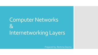
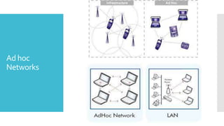
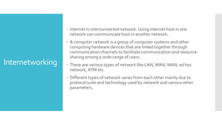
1) Computer networks allow communication and sharing of resources between computer systems and devices through communication channels. There are several types of networks including LANs, WANs, and MANs.
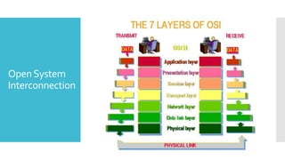
2) For communication between systems, both must agree on a protocol which sets rules for data transmission. The two main protocol stacks are OSI and TCP/IP.
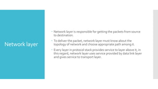
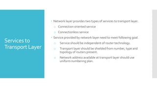
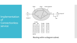
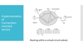
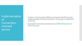
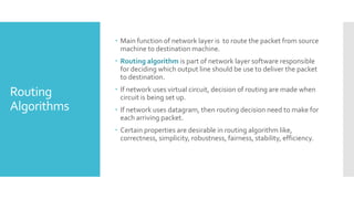
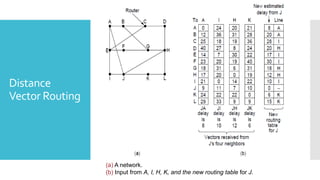
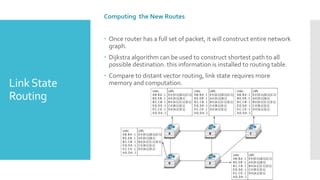
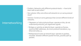
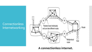
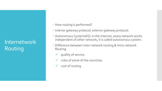
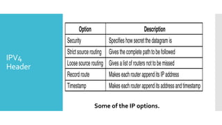
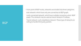
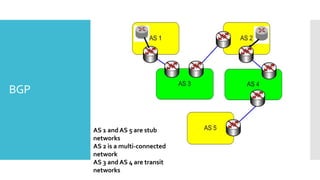
3) The network layer is responsible for delivering packets from source to destination. It uses services from the data link layer and provides services to the transport layer. Common network layer protocols are IP (Internet Protocol) for connectionless service and MPLS for connection-oriented service.


![Unit-3-Part-1 [Autosaved].ppt](https://cdn.slidesharecdn.com/ss_thumbnails/unit-3-part-1autosaved-230216062941-16596250-thumbnail.jpg?width=640&height=640&fit=bounds)