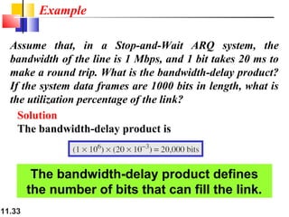
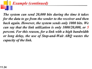
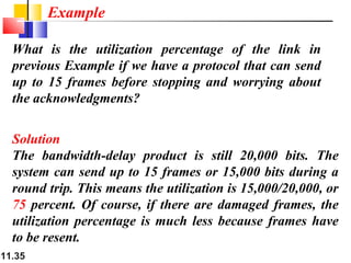
The document discusses data link layer protocols:
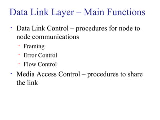
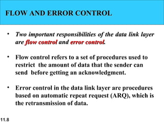
1. It describes the main functions of the data link layer including data link control, framing, error control, flow control, and media access control.
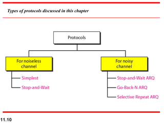
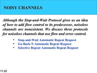
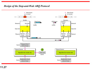
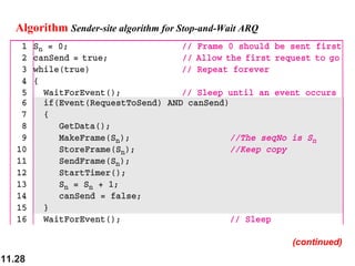
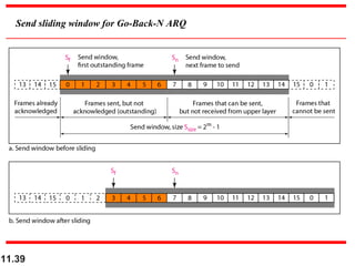
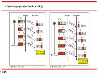
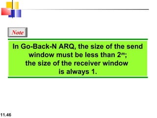
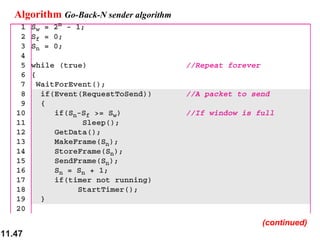
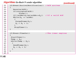
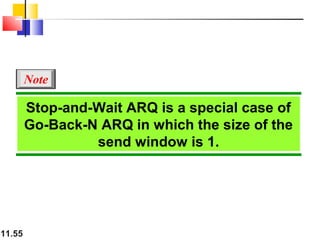
2. It introduces the Stop-and-Wait ARQ, Go-Back-N ARQ, and Selective Repeat ARQ protocols which combine framing, flow control, and error control to deliver data from one node to another over noisy channels.
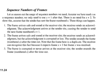
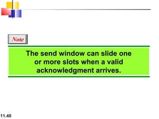
3. It explains how these protocols use sequence numbers, sliding windows, and acknowledgments to provide flow and error control.