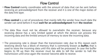
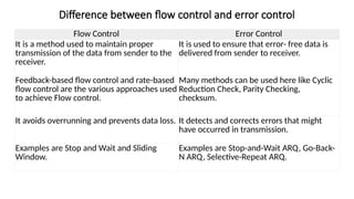
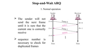
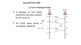
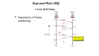
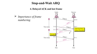
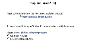
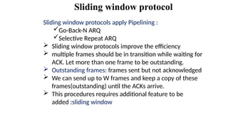
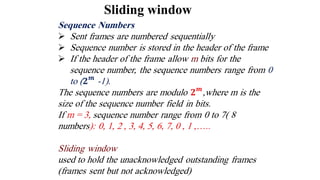
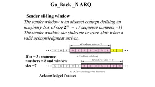
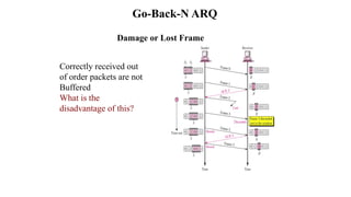
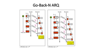
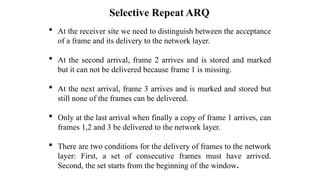
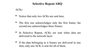
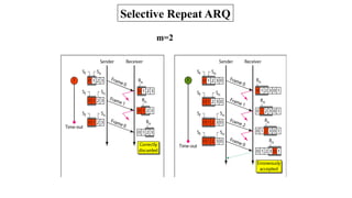
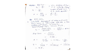
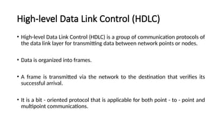
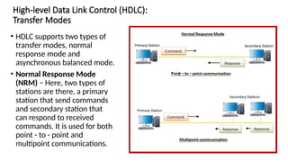
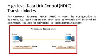
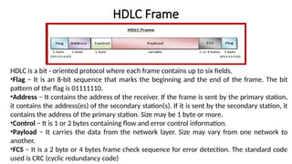
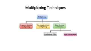
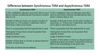
Data Communications
Lecture 36-43
Dr. Rajat Goel
Contents
Error Control: Stop-and-wait ARQ
Go-back- N ARQ
SR ARQ
Flow and Error Control
HDLC, Configurations and Transfer Modes, Framing
Time-Division, Multiplexing (TDM)
Tutorial – Multiplexing
Error Control
• Error control is concerned with ensuring that all frames are delivered to destination
possibly in an order.
• Error Control contains both error detection and error correction. It mainly allows the
receiver to inform the sender about any damaged or lost frames during the
transmission and then it coordinates with the retransmission of those frames by the
sender.
• Error control is mainly implemented in a simple way and that is whenever there is
an error detected during the exchange, then specified frames are retransmitted and
this process is also referred to as Automatic Repeat request (ARQ).
Error Control
To ensure the delivery it requires three items:
1. Acknowledgement: Typically, reliable delivery is achieved using the “acknowledgement
with retransmission” paradigm, whereas the receiver returns a special ACK frame to the
sender indicating the correct receipt of a frame. In some systems the receiver also returns
a negative ACK (NACK) for incorrectly received frames. So, it tells the sender to retransmit
a frame without waiting for a timer to expire.
2. Timers: One problem that simple ACK/NACK schemes fail to address is recovering from a
frame that is lost, and as a result, fails to solicit an ACK or NACK. Retransmission timers are
used to resend frames that don’t produce an ACK. When we are sending a frame,
schedule a timer so that it expires at some time after the ACK should have been returned.
If the timer goes 0, then retransmit the frame.
3. Sequence Number: Retransmission introduces the possibility of duplicate frames. To
reduce duplicates, we must add sequence numbers to each frame, so that a receiver can
distinguish between new frames and old frames.
Flow Control
• Flow Control mainly coordinates with the amount of data that can be sent before
receiving an acknowledgment from the receiver and it is one of the major duties of
the data link layer.
• Flow control is a set of procedures that mainly tells the sender how much data the
sender can send before it must wait for an acknowledgment from the receiver.
• The data flow must not be allowed to overwhelm the receiver; because any
receiving device has a very limited speed at which the device can process the
incoming data and the limited amount of memory to store the incoming data.
• The processing rate is slower than the transmission rate; due to this reason each
receiving device has a block of memory that is commonly known as buffer, that is
used to store the incoming data until this data will be processed. In case the buffer
begins to fill up then the receiver must be able to tell the sender to halt the
transmission until once again the receiver become able to receive.
Flow Control
• Thus the flow control makes the sender; wait for the acknowledgment
from the receiver before the continuation to send more data to the
receiver.
• Some of the common flow control techniques are: Stop-and-Wait and
sliding window technique.
Difference between flow control and error control
Flow Control Error Control
It is a method used to maintain proper
transmission of the data from sender to the
receiver.
It is used to ensure that error- free data is
delivered from sender to receiver.
Feedback-based flow control and rate-based
flow control are the various approaches used
to achieve Flow control.
Many methods can be used here like Cyclic
Reduction Check, Parity Checking,
checksum.
It avoids overrunning and prevents data loss. It detects and corrects errors that might
have occurred in transmission.
Examples are Stop and Wait and Sliding
Window.
Examples are Stop-and-Wait ARQ, Go-Back-
N ARQ, Selective-Repeat ARQ.
Forward Error
Correction Protocols
PROTOCOLS
Noisy Channel
Stop-and-Wait ARQ
Go-Back-N ARQ
Selective Repeat ARQ
Noiseless Channel
Simplex
Simplex Stop and Wait
 It is the simplest flow and error control mechanism . A transmitter sends a
frame then stops and waits for an acknowledgment.
 The sending device keeps a copy of the sent frame transmitted until it
receives an acknowledgment( ACK)
 The sender starts a timer when it sends a frame. If an ACK is not received
within an allocated time period, the sender resends it
 Both frames and acknowledgment (ACK) are numbered alternately 0 and
1( two sequence number only)
 This numbering allows for identification of frames in case of duplicate
transmission
Stop-and-Wait ARQ
 If the receiver detects an error in the received frame, or receives a frame out
of order it simply discards the frame
 The receiver send ACK for frames received safe
 The sender has a control variable S that holds the number of most recently
sent frame (0 or 1). The receiver has control variable R, that holds the
number of the next frame expected (0or 1)
Stop-and-Wait ARQ
Cases of Operations:
1. Normal operation
2. The frame is lost
3. The Acknowledgment (ACK) is lost
4. The Ack is delayed
Stop-and-Wait ARQ
1. Normal operation
 The sender will not
send the next frame
until it is sure that the
current one is correctly
receive
 sequence number is
necessary to check for
duplicated frames
Stop-and-Wait ARQ
Stop and Wait ARQ
2. Lost or damaged frame
 A damage or lost frame
treated by the same manner
by the receiver.
 No ACK when frame is
corrupted / duplicate
3. Lost ACK frame
 Importance of frame
numbering
Stop-and-Wait ARQ
4. Delayed ACK and lost frame
 Importance of frame
numbering
Stop-and-Wait ARQ
After each frame sent the host must wait for an ACK
inefficient use of bandwidth
To improve efficiency ACK should be sent after multiple frames
Alternatives: Sliding Window protocol
 Go-back-N ARQ
 Selective Repeat ARQ
Stop-and-Wait ARQ
Sliding window protocol
Sliding window protocols apply Pipelining :
Go-Back-N ARQ
Selective Repeat ARQ
 Sliding window protocols improve the efficiency
 multiple frames should be in transition while waiting for
ACK. Let more than one frame to be outstanding.
 Outstanding frames: frames sent but not acknowledged
 We can send up to W frames and keep a copy of these
frames(outstanding) until the ACKs arrive.
 This procedures requires additional feature to be
added :sliding window
Sliding window
Go_Back _N ARQ
Sender sliding window
If m = 3; sequence
numbers = 8 and window
size =7
Acknowledged frames
Receiver sliding window
 The receive window is an abstract concept defining
an imaginary box of size 1 with one single variable
Rn.
 The window slides when a correct frame has arrived;
sliding occurs one slot at a time.
Go_Back _N ARQ
control variables
S: hold the sequence number of the recently sent frame
SF: holds sequence number of the first frame in the
window
SL: holds the sequence number of the last frame
R: sequence number of the frame expected to received
Outstanding frames: frames sent but not
acknowledged
Go-Back-N ARQ
In Go-Back-N ARQ we use one timer for the first outstanding
frame
 The receiver sends a positive ACK if a frame has arrived safe
and in order.
 if a frame is damaged or out of order ,the receiver is silent and
will discard all subsequent frames
 When the timer of an unacknowledged frame at the sender site
is expired , the sender goes back and resend all frames,
beginning with the one with expired timer.( that is why the
protocol is called Go-Back-N ARQ)
 The receiver doesn't have to acknowledge each frame
received . It can send cumulative Ack for several frame
Go-Back-N ARQ
Go-Back-N ARQ
Normal operation
 How many frame scan
be transmitted Without
acknowledgment?
 ACK1 is not necessary
if ACK2 is sent:
Cumulative ACK
Go-Back-N ARQ
Damage or Lost Frame
Correctly received out
of order packets are not
Buffered
What is the
disadvantage of this?
Go-Back-N ARQ
Go-Back-N ARQ
Selective Repeat ARQ
Go-Back-N ARQ is inefficient of a noisy link.
 In a noisy link frames have higher probability of damage , which
means the resending of multiple frames.
 this resending consumes the bandwidth and slow down the
transmission .
Solution:
 Selective Repeat ARQ protocol : resent only the damage frame
 It defines a negative Acknowlgment (NAK) that report the sequence
number of a damaged frame before the timer expires
 It is more efficient for noisy link, but the processing at the receiver is
more complex
Selective Repeat ARQ
m=3
Sequences no=2m
=8
0,1,2 ,3,4,5,6,7
Window size =2m
/2=4
Lost Frame
Selective Repeat ARQ
 At the receiver site we need to distinguish between the acceptance
of a frame and its delivery to the network layer.
 At the second arrival, frame 2 arrives and is stored and marked
but it can not be delivered because frame 1 is missing.
 At the next arrival, frame 3 arrives and is marked and stored but
still none of the frames can be delivered.
 Only at the last arrival when finally a copy of frame 1 arrives, can
frames 1,2 and 3 be delivered to the network layer.
 There are two conditions for the delivery of frames to the network
layer: First, a set of consecutive frames must have arrived.
Second, the set starts from the beginning of the window.
Selective Repeat ARQ
ACKs
 Notice that only two ACKs are sent here.
 The first one acknowledges only the first frame; the
second one acknowledges three frames.
 In Selective Repeat, ACKs are sent when data are
delivered to the network layer.
 If the data belonging to n frames are delivered in one
shot, only one ACK is sent for all of them.
Selective Repeat ARQ
m=2
Protocol Performance of ARQ
High-level Data Link Control (HDLC)
• High-level Data Link Control (HDLC) is a group of communication protocols of
the data link layer for transmitting data between network points or nodes.
• Data is organized into frames.
• A frame is transmitted via the network to the destination that verifies its
successful arrival.
• It is a bit - oriented protocol that is applicable for both point - to - point and
multipoint communications.
High-level Data Link Control (HDLC):
Transfer Modes
• HDLC supports two types of
transfer modes, normal
response mode and
asynchronous balanced mode.
• Normal Response Mode
(NRM) − Here, two types of
stations are there, a primary
station that send commands
and secondary station that
can respond to received
commands. It is used for both
point - to - point and
multipoint communications.
High-level Data Link Control (HDLC):
Transfer Modes
Asynchronous Balanced Mode (ABM) − Here, the configuration is
balanced, i.e. each station can both send commands and respond to
commands. It is used for only point - to - point communications.
HDLC Frame
HDLC is a bit - oriented protocol where each frame contains up to six fields.
•Flag − It is an 8-bit sequence that marks the beginning and the end of the frame. The bit
pattern of the flag is 01111110.
•Address − It contains the address of the receiver. If the frame is sent by the primary station,
it contains the address(es) of the secondary station(s). If it is sent by the secondary station, it
contains the address of the primary station. Size may be 1 byte or more.
•Control − It is 1 or 2 bytes containing flow and error control information.
•Payload − It carries the data from the network layer. Size may vary from one network to
another.
•FCS − It is a 2 byte or 4 bytes frame check sequence for error detection. The standard code
used is CRC (cyclic redundancy code)
• There are three types of HDLC frames. The type of frame is determined by the control field
of the frame −
• I-frame − I-frames or Information frames carry user data from the network layer. They also
include flow and error control information that is piggybacked on user data. The first bit of
control field of I-frame is 0.
• S-frame − S-frames or Supervisory frames do not contain information field. They are used
for flow and error control when piggybacking is not required. The first two bits of control
field of S-frame is 10.
• U-frame − U-frames or Un-numbered frames are used for myriad miscellaneous functions,
like link management. It may contain an information field, if required. The first two bits of
control field of U-frame is 11.
HDLC Frame
• There are three types of HDLC frames. The type of frame is determined by the
control field of the frame −
• I-frame − I-frames or Information frames carry user data from the network
layer. They also include flow and error control information that is piggybacked
on user data. The first bit of control field of I-frame is 0.
• S-frame − S-frames or Supervisory frames do not contain information field.
They are used for flow and error control when piggybacking is not required.
The first two bits of control field of S-frame is 10.
• U-frame − U-frames or Un-numbered frames are used for myriad
miscellaneous functions, like link management. It may contain an information
field, if required. The first two bits of control field of U-frame is 11.
HDLC Frame
Multiplexing
Technique used to combine and send the multiple data streams over a single
medium.
• Multiplexing is achieved by using a device called Multiplexer (MUX) that
combines n input lines to generate a single output line. Multiplexing follows
many-to-one, i.e., n input lines and one output line.
• Demultiplexing is achieved by using a device called Demultiplexer (DEMUX)
available at the receiving end. DEMUX separates a signal into its component
signals (one input and n outputs). Therefore, we can say that demultiplexing
follows the one-to-many approach.
Need of Multiplexing
• The transmission medium is used to send the signal from sender to receiver.
• The medium can only have one signal at a time.
• If there are multiple signals to share one medium, then the medium must be divided in such a
way that each signal is given some portion of the available bandwidth. For example: If there
are 10 signals and bandwidth of medium is 100 units, then the 10 unit is shared by each signal.
• When multiple signals share the common medium, there is a possibility of collision.
• Multiplexing concept is used to avoid such collision.
Concept of Multiplexing
• The 'n' input lines are transmitted through a multiplexer and multiplexer combines the
signals to form a composite signal.
• The composite signal is passed through a Demultiplexer and demultiplexer separates a
signal to component signals and transfers them to their respective destinations.
Advantages of Multiplexing:
• More than one signal can be sent over a single medium.
• The bandwidth of a medium can be utilized effectively.
Multiplexing Techniques
Time Division Multiplexing
• It is a digital technique.
• All signals operate at the same frequency with different time.
• The total time available in the channel is distributed among different users.
Therefore, each user is allocated with different time interval known as a Time slot
at which data is to be transmitted by the sender.
• A user takes control of the channel for a fixed amount of time.
• Data is not transmitted simultaneously but one-by-one.
• The signal is transmitted in the form of frames.
• Frames contain a cycle of time slots in which each frame contains one or more
slots dedicated to each user.
• It can be used to multiplex both digital and analog signals.
Types of TDM:
• Synchronous TDM
• Asynchronous TDM
Synchronous TDM
• Each device is given same time slot to transmit the data over the link, irrespective of the
fact that the device has any data to transmit or not.
• Synchronous TDM requires that the total speed of various input lines should not exceed
the capacity of path.
• Each device places its data onto the link when its time slot arrives i.e. each device is
given the possession of line turn by turn.
• If any device does not have data to send then its time slot remains empty.
• The various time slots are organized into frames and each frame consists of one or
more time slots dedicated to each sending device.
• If there are n sending devices, there will be n slots in frame i.e. one slot for each device.
Asynchronous TDM
• It is also known as statistical time division multiplexing.
• Asynchronous TDM is called so because is this type of multiplexing, time slots
are not fixed i.e. the slots are flexible.
• Here, the total speed of input lines can be greater than the capacity of the path.
• In synchronous TDM, if we have n input lines then there are n slots in one frame.
But in asynchronous it is not so.
• In asynchronous TDM, if we have n input lines then the frame contains not more
than m slots, with m less than n (m < n).
• In asynchronous TDM, the number of time slots in a frame is based on a
statistical analysis of number of input lines.
Asynchronous TDM
• In this system slots are not pre-
defined, the slots are allocated
to any of the device that has
data to send.
• The multiplexer scans the
various input lines, accepts the
data from the lines that have
data to send, fills the frame and
then sends the frame across the
link.
• If there are not enough data to
fill all the slots in a frame, then
the frames are transmitted
partially filled.
Difference between Synchronous TDM and Asynchronous TDM
Synchronous TDM Asynchronous TDM
In this, multiplexer allocates same time slots to each
device without considering fact that device contains
data or not.
In this, multiplexer does not allocates same time
slots to each device without considering fact that
device contains data or not.
Number of slots per frame are equal to number of
input lines i.e., If it contains n input lines, then it
must have n slots in one frame.
Number of slots per frame are less than number of
input lines i.e., If there are n input lines, then there
are m slots in one frame (m<n).
There is no guarantee that full capacity link is used. There is guarantee that full capacity link is used.
Total speed of input lines cannot be greater than
capacity of path.
Total speed of input lines can be greater than
capacity of path.
Usage of devices is less. Usage of devices is more.
Number of time slots in a frame as always based on
number of input lines.
Number of time slots in a frame as always based on
statistical analysis of number of input lines that are
likely to be transmitting at any given time.
Time slots are fixed and pre-defined. Time-slots are not pre-defined.

Lecture 36-43_DATA_COMMUNICATION_PPT.pptx

  • 1.
  • 2.
    Contents Error Control: Stop-and-waitARQ Go-back- N ARQ SR ARQ Flow and Error Control HDLC, Configurations and Transfer Modes, Framing Time-Division, Multiplexing (TDM) Tutorial – Multiplexing
  • 3.
    Error Control • Errorcontrol is concerned with ensuring that all frames are delivered to destination possibly in an order. • Error Control contains both error detection and error correction. It mainly allows the receiver to inform the sender about any damaged or lost frames during the transmission and then it coordinates with the retransmission of those frames by the sender. • Error control is mainly implemented in a simple way and that is whenever there is an error detected during the exchange, then specified frames are retransmitted and this process is also referred to as Automatic Repeat request (ARQ).
  • 4.
    Error Control To ensurethe delivery it requires three items: 1. Acknowledgement: Typically, reliable delivery is achieved using the “acknowledgement with retransmission” paradigm, whereas the receiver returns a special ACK frame to the sender indicating the correct receipt of a frame. In some systems the receiver also returns a negative ACK (NACK) for incorrectly received frames. So, it tells the sender to retransmit a frame without waiting for a timer to expire. 2. Timers: One problem that simple ACK/NACK schemes fail to address is recovering from a frame that is lost, and as a result, fails to solicit an ACK or NACK. Retransmission timers are used to resend frames that don’t produce an ACK. When we are sending a frame, schedule a timer so that it expires at some time after the ACK should have been returned. If the timer goes 0, then retransmit the frame. 3. Sequence Number: Retransmission introduces the possibility of duplicate frames. To reduce duplicates, we must add sequence numbers to each frame, so that a receiver can distinguish between new frames and old frames.
  • 5.
    Flow Control • FlowControl mainly coordinates with the amount of data that can be sent before receiving an acknowledgment from the receiver and it is one of the major duties of the data link layer. • Flow control is a set of procedures that mainly tells the sender how much data the sender can send before it must wait for an acknowledgment from the receiver. • The data flow must not be allowed to overwhelm the receiver; because any receiving device has a very limited speed at which the device can process the incoming data and the limited amount of memory to store the incoming data. • The processing rate is slower than the transmission rate; due to this reason each receiving device has a block of memory that is commonly known as buffer, that is used to store the incoming data until this data will be processed. In case the buffer begins to fill up then the receiver must be able to tell the sender to halt the transmission until once again the receiver become able to receive.
  • 6.
    Flow Control • Thusthe flow control makes the sender; wait for the acknowledgment from the receiver before the continuation to send more data to the receiver. • Some of the common flow control techniques are: Stop-and-Wait and sliding window technique.
  • 7.
    Difference between flowcontrol and error control Flow Control Error Control It is a method used to maintain proper transmission of the data from sender to the receiver. It is used to ensure that error- free data is delivered from sender to receiver. Feedback-based flow control and rate-based flow control are the various approaches used to achieve Flow control. Many methods can be used here like Cyclic Reduction Check, Parity Checking, checksum. It avoids overrunning and prevents data loss. It detects and corrects errors that might have occurred in transmission. Examples are Stop and Wait and Sliding Window. Examples are Stop-and-Wait ARQ, Go-Back- N ARQ, Selective-Repeat ARQ.
  • 8.
  • 9.
    PROTOCOLS Noisy Channel Stop-and-Wait ARQ Go-Back-NARQ Selective Repeat ARQ Noiseless Channel Simplex Simplex Stop and Wait
  • 10.
     It isthe simplest flow and error control mechanism . A transmitter sends a frame then stops and waits for an acknowledgment.  The sending device keeps a copy of the sent frame transmitted until it receives an acknowledgment( ACK)  The sender starts a timer when it sends a frame. If an ACK is not received within an allocated time period, the sender resends it  Both frames and acknowledgment (ACK) are numbered alternately 0 and 1( two sequence number only)  This numbering allows for identification of frames in case of duplicate transmission Stop-and-Wait ARQ
  • 11.
     If thereceiver detects an error in the received frame, or receives a frame out of order it simply discards the frame  The receiver send ACK for frames received safe  The sender has a control variable S that holds the number of most recently sent frame (0 or 1). The receiver has control variable R, that holds the number of the next frame expected (0or 1) Stop-and-Wait ARQ
  • 12.
    Cases of Operations: 1.Normal operation 2. The frame is lost 3. The Acknowledgment (ACK) is lost 4. The Ack is delayed Stop-and-Wait ARQ
  • 13.
    1. Normal operation The sender will not send the next frame until it is sure that the current one is correctly receive  sequence number is necessary to check for duplicated frames Stop-and-Wait ARQ
  • 14.
    Stop and WaitARQ 2. Lost or damaged frame  A damage or lost frame treated by the same manner by the receiver.  No ACK when frame is corrupted / duplicate
  • 15.
    3. Lost ACKframe  Importance of frame numbering Stop-and-Wait ARQ
  • 16.
    4. Delayed ACKand lost frame  Importance of frame numbering Stop-and-Wait ARQ
  • 17.
    After each framesent the host must wait for an ACK inefficient use of bandwidth To improve efficiency ACK should be sent after multiple frames Alternatives: Sliding Window protocol  Go-back-N ARQ  Selective Repeat ARQ Stop-and-Wait ARQ
  • 18.
    Sliding window protocol Slidingwindow protocols apply Pipelining : Go-Back-N ARQ Selective Repeat ARQ  Sliding window protocols improve the efficiency  multiple frames should be in transition while waiting for ACK. Let more than one frame to be outstanding.  Outstanding frames: frames sent but not acknowledged  We can send up to W frames and keep a copy of these frames(outstanding) until the ACKs arrive.  This procedures requires additional feature to be added :sliding window
  • 19.
  • 20.
    Go_Back _N ARQ Sendersliding window If m = 3; sequence numbers = 8 and window size =7 Acknowledged frames
  • 21.
    Receiver sliding window The receive window is an abstract concept defining an imaginary box of size 1 with one single variable Rn.  The window slides when a correct frame has arrived; sliding occurs one slot at a time. Go_Back _N ARQ
  • 22.
    control variables S: holdthe sequence number of the recently sent frame SF: holds sequence number of the first frame in the window SL: holds the sequence number of the last frame R: sequence number of the frame expected to received Outstanding frames: frames sent but not acknowledged Go-Back-N ARQ
  • 23.
    In Go-Back-N ARQwe use one timer for the first outstanding frame  The receiver sends a positive ACK if a frame has arrived safe and in order.  if a frame is damaged or out of order ,the receiver is silent and will discard all subsequent frames  When the timer of an unacknowledged frame at the sender site is expired , the sender goes back and resend all frames, beginning with the one with expired timer.( that is why the protocol is called Go-Back-N ARQ)  The receiver doesn't have to acknowledge each frame received . It can send cumulative Ack for several frame Go-Back-N ARQ
  • 24.
    Go-Back-N ARQ Normal operation How many frame scan be transmitted Without acknowledgment?  ACK1 is not necessary if ACK2 is sent: Cumulative ACK
  • 25.
    Go-Back-N ARQ Damage orLost Frame Correctly received out of order packets are not Buffered What is the disadvantage of this?
  • 26.
  • 27.
  • 28.
    Selective Repeat ARQ Go-Back-NARQ is inefficient of a noisy link.  In a noisy link frames have higher probability of damage , which means the resending of multiple frames.  this resending consumes the bandwidth and slow down the transmission . Solution:  Selective Repeat ARQ protocol : resent only the damage frame  It defines a negative Acknowlgment (NAK) that report the sequence number of a damaged frame before the timer expires  It is more efficient for noisy link, but the processing at the receiver is more complex
  • 29.
  • 30.
    Selective Repeat ARQ m=3 Sequencesno=2m =8 0,1,2 ,3,4,5,6,7 Window size =2m /2=4 Lost Frame
  • 31.
    Selective Repeat ARQ At the receiver site we need to distinguish between the acceptance of a frame and its delivery to the network layer.  At the second arrival, frame 2 arrives and is stored and marked but it can not be delivered because frame 1 is missing.  At the next arrival, frame 3 arrives and is marked and stored but still none of the frames can be delivered.  Only at the last arrival when finally a copy of frame 1 arrives, can frames 1,2 and 3 be delivered to the network layer.  There are two conditions for the delivery of frames to the network layer: First, a set of consecutive frames must have arrived. Second, the set starts from the beginning of the window.
  • 32.
    Selective Repeat ARQ ACKs Notice that only two ACKs are sent here.  The first one acknowledges only the first frame; the second one acknowledges three frames.  In Selective Repeat, ACKs are sent when data are delivered to the network layer.  If the data belonging to n frames are delivered in one shot, only one ACK is sent for all of them.
  • 33.
  • 34.
  • 36.
    High-level Data LinkControl (HDLC) • High-level Data Link Control (HDLC) is a group of communication protocols of the data link layer for transmitting data between network points or nodes. • Data is organized into frames. • A frame is transmitted via the network to the destination that verifies its successful arrival. • It is a bit - oriented protocol that is applicable for both point - to - point and multipoint communications.
  • 37.
    High-level Data LinkControl (HDLC): Transfer Modes • HDLC supports two types of transfer modes, normal response mode and asynchronous balanced mode. • Normal Response Mode (NRM) − Here, two types of stations are there, a primary station that send commands and secondary station that can respond to received commands. It is used for both point - to - point and multipoint communications.
  • 38.
    High-level Data LinkControl (HDLC): Transfer Modes Asynchronous Balanced Mode (ABM) − Here, the configuration is balanced, i.e. each station can both send commands and respond to commands. It is used for only point - to - point communications.
  • 39.
    HDLC Frame HDLC isa bit - oriented protocol where each frame contains up to six fields. •Flag − It is an 8-bit sequence that marks the beginning and the end of the frame. The bit pattern of the flag is 01111110. •Address − It contains the address of the receiver. If the frame is sent by the primary station, it contains the address(es) of the secondary station(s). If it is sent by the secondary station, it contains the address of the primary station. Size may be 1 byte or more. •Control − It is 1 or 2 bytes containing flow and error control information. •Payload − It carries the data from the network layer. Size may vary from one network to another. •FCS − It is a 2 byte or 4 bytes frame check sequence for error detection. The standard code used is CRC (cyclic redundancy code)
  • 40.
    • There arethree types of HDLC frames. The type of frame is determined by the control field of the frame − • I-frame − I-frames or Information frames carry user data from the network layer. They also include flow and error control information that is piggybacked on user data. The first bit of control field of I-frame is 0. • S-frame − S-frames or Supervisory frames do not contain information field. They are used for flow and error control when piggybacking is not required. The first two bits of control field of S-frame is 10. • U-frame − U-frames or Un-numbered frames are used for myriad miscellaneous functions, like link management. It may contain an information field, if required. The first two bits of control field of U-frame is 11. HDLC Frame
  • 41.
    • There arethree types of HDLC frames. The type of frame is determined by the control field of the frame − • I-frame − I-frames or Information frames carry user data from the network layer. They also include flow and error control information that is piggybacked on user data. The first bit of control field of I-frame is 0. • S-frame − S-frames or Supervisory frames do not contain information field. They are used for flow and error control when piggybacking is not required. The first two bits of control field of S-frame is 10. • U-frame − U-frames or Un-numbered frames are used for myriad miscellaneous functions, like link management. It may contain an information field, if required. The first two bits of control field of U-frame is 11. HDLC Frame
  • 43.
    Multiplexing Technique used tocombine and send the multiple data streams over a single medium. • Multiplexing is achieved by using a device called Multiplexer (MUX) that combines n input lines to generate a single output line. Multiplexing follows many-to-one, i.e., n input lines and one output line. • Demultiplexing is achieved by using a device called Demultiplexer (DEMUX) available at the receiving end. DEMUX separates a signal into its component signals (one input and n outputs). Therefore, we can say that demultiplexing follows the one-to-many approach.
  • 44.
    Need of Multiplexing •The transmission medium is used to send the signal from sender to receiver. • The medium can only have one signal at a time. • If there are multiple signals to share one medium, then the medium must be divided in such a way that each signal is given some portion of the available bandwidth. For example: If there are 10 signals and bandwidth of medium is 100 units, then the 10 unit is shared by each signal. • When multiple signals share the common medium, there is a possibility of collision. • Multiplexing concept is used to avoid such collision.
  • 45.
    Concept of Multiplexing •The 'n' input lines are transmitted through a multiplexer and multiplexer combines the signals to form a composite signal. • The composite signal is passed through a Demultiplexer and demultiplexer separates a signal to component signals and transfers them to their respective destinations. Advantages of Multiplexing: • More than one signal can be sent over a single medium. • The bandwidth of a medium can be utilized effectively.
  • 46.
  • 47.
    Time Division Multiplexing •It is a digital technique. • All signals operate at the same frequency with different time. • The total time available in the channel is distributed among different users. Therefore, each user is allocated with different time interval known as a Time slot at which data is to be transmitted by the sender. • A user takes control of the channel for a fixed amount of time. • Data is not transmitted simultaneously but one-by-one. • The signal is transmitted in the form of frames. • Frames contain a cycle of time slots in which each frame contains one or more slots dedicated to each user. • It can be used to multiplex both digital and analog signals.
  • 48.
    Types of TDM: •Synchronous TDM • Asynchronous TDM
  • 49.
    Synchronous TDM • Eachdevice is given same time slot to transmit the data over the link, irrespective of the fact that the device has any data to transmit or not. • Synchronous TDM requires that the total speed of various input lines should not exceed the capacity of path. • Each device places its data onto the link when its time slot arrives i.e. each device is given the possession of line turn by turn. • If any device does not have data to send then its time slot remains empty. • The various time slots are organized into frames and each frame consists of one or more time slots dedicated to each sending device. • If there are n sending devices, there will be n slots in frame i.e. one slot for each device.
  • 50.
    Asynchronous TDM • Itis also known as statistical time division multiplexing. • Asynchronous TDM is called so because is this type of multiplexing, time slots are not fixed i.e. the slots are flexible. • Here, the total speed of input lines can be greater than the capacity of the path. • In synchronous TDM, if we have n input lines then there are n slots in one frame. But in asynchronous it is not so. • In asynchronous TDM, if we have n input lines then the frame contains not more than m slots, with m less than n (m < n). • In asynchronous TDM, the number of time slots in a frame is based on a statistical analysis of number of input lines.
  • 51.
    Asynchronous TDM • Inthis system slots are not pre- defined, the slots are allocated to any of the device that has data to send. • The multiplexer scans the various input lines, accepts the data from the lines that have data to send, fills the frame and then sends the frame across the link. • If there are not enough data to fill all the slots in a frame, then the frames are transmitted partially filled.
  • 52.
    Difference between SynchronousTDM and Asynchronous TDM Synchronous TDM Asynchronous TDM In this, multiplexer allocates same time slots to each device without considering fact that device contains data or not. In this, multiplexer does not allocates same time slots to each device without considering fact that device contains data or not. Number of slots per frame are equal to number of input lines i.e., If it contains n input lines, then it must have n slots in one frame. Number of slots per frame are less than number of input lines i.e., If there are n input lines, then there are m slots in one frame (m<n). There is no guarantee that full capacity link is used. There is guarantee that full capacity link is used. Total speed of input lines cannot be greater than capacity of path. Total speed of input lines can be greater than capacity of path. Usage of devices is less. Usage of devices is more. Number of time slots in a frame as always based on number of input lines. Number of time slots in a frame as always based on statistical analysis of number of input lines that are likely to be transmitting at any given time. Time slots are fixed and pre-defined. Time-slots are not pre-defined.