Downloaded 107 times
![Sections in Part – A [ Network Models ]
Layered Tasks
OSI Model
~ Introduction
~ Layers in OSI Model
TCP / IP Model
Addressing](https://image.slidesharecdn.com/unit1networkmodelstypicalexamplespart-a-140901094124-phpapp01/85/Unit-1-network-models-typical-examples-part-a-4-320.jpg)
![2-1 LAYERED TASKS
Understanding Layered Tasks . . . . . . . . . . .
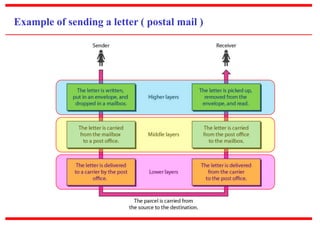
* We use the concept of layers in our daily life.
* Example :
Consider two friends who communicate through postal mail.
[ i.e. one friend sends a letter to another friend ]](https://image.slidesharecdn.com/unit1networkmodelstypicalexamplespart-a-140901094124-phpapp01/85/Unit-1-network-models-typical-examples-part-a-5-320.jpg)
![Some notable points from the previous example . . . . . .
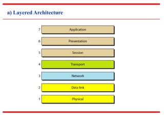
Components - The three vital components in any communication
system are : Sender, Receiver and Carrier
Hierarchy - Layers do exist on both the sites and these layers are
arranged in particular order. In other words, a particular
hierarchy of layers exists. [ Order Matters ! ]
Services – Each layer at the sending site uses the services of the
layer immediately below it; while each layer at the receiving site
provides the services to the layer immediately above it.](https://image.slidesharecdn.com/unit1networkmodelstypicalexamplespart-a-140901094124-phpapp01/85/Unit-1-network-models-typical-examples-part-a-7-320.jpg)
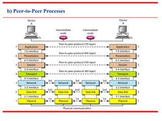
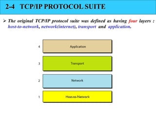
![ The layers in the TCP/IP protocol suite do not exactly match
those in the OSI model.
However, when TCP/IP is compared to OSI, we can say
that the TCP/IP protocol suite is made of five layers:
physical, data link, network, transport, and application
[next slide . . . . ]](https://image.slidesharecdn.com/unit1networkmodelstypicalexamplespart-a-140901094124-phpapp01/85/Unit-1-network-models-typical-examples-part-a-26-320.jpg)
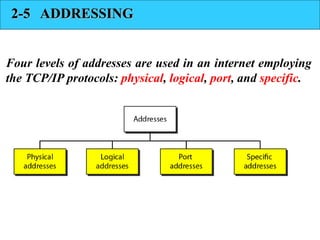
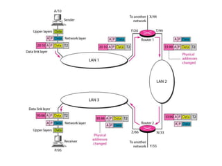
![2. Logical Address :
A logical address in the Internet is currently 32-bit
address that can uniquely define a host connected to the
Internet.
~ No two publicly addressed and visible hosts on the Internet
can have the same IP address.
[ Note : IP address is typical example of Logical Address on present day Internet ]](https://image.slidesharecdn.com/unit1networkmodelstypicalexamplespart-a-140901094124-phpapp01/85/Unit-1-network-models-typical-examples-part-a-33-320.jpg)

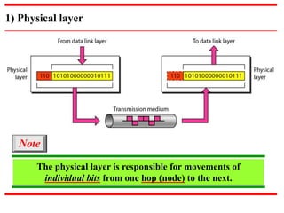
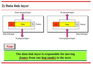
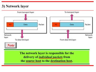
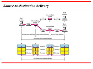
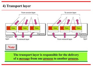
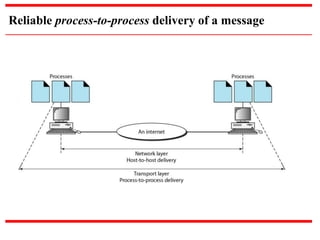
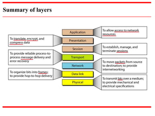
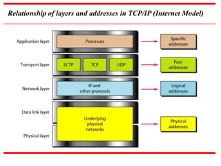
The document discusses network models and examples. It describes the layered OSI model and TCP/IP model, including the functions of each layer. The physical layer deals with bit transmission between nodes. The data link layer handles frame delivery between nodes. The network layer delivers packets from source to destination host. The transport layer provides reliable message delivery between processes. The OSI model aims to standardize network communication and has 7 layers, while the TCP/IP model used on the internet has 5 layers that overlap with OSI. Network addresses include physical, logical, port, and specific addresses.