SlideShare a Scribd company logo
1 of 103
11.1
Chapter 11
Data Link Control
Copyright © The McGraw-Hill Companies, Inc. Permission required for reproduction or display.
11.2
11-1 FRAMING11-1 FRAMING
The data link layer needs to pack bits intoThe data link layer needs to pack bits into framesframes, so, so
that each frame is distinguishable from another. Ourthat each frame is distinguishable from another. Our
postal system practices a type of framing. The simplepostal system practices a type of framing. The simple
act of inserting a letter into an envelope separates oneact of inserting a letter into an envelope separates one
piece of information from another; the envelope servespiece of information from another; the envelope serves
as the delimiter.as the delimiter.
Fixed-Size Framing
Variable-Size Framing
Topics discussed in this section:Topics discussed in this section:
11.3
Figure 11.1 A frame in a character-oriented protocol
11.4
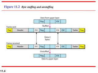
Figure 11.2 Byte stuffing and unstuffing
11.5
Byte stuffing is the process of adding 1
extra byte whenever there is a flag or
escape character in the text.
Note
11.6
Figure 11.3 A frame in a bit-oriented protocol
11.7
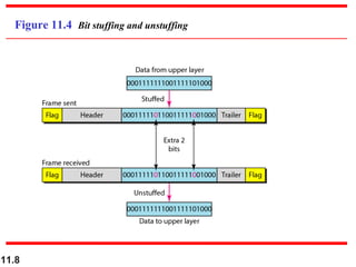
Bit stuffing is the process of adding one
extra 0 whenever five consecutive 1s
follow a 0 in the data, so that the
receiver does not mistake
the pattern 0111110 for a flag.
Note
11.8
Figure 11.4 Bit stuffing and unstuffing
11.9
11-2 FLOW AND ERROR CONTROL11-2 FLOW AND ERROR CONTROL
The most important responsibilities of the data linkThe most important responsibilities of the data link
layer arelayer are flow controlflow control andand error controlerror control. Collectively,. Collectively,
these functions are known asthese functions are known as data link controldata link control..
Flow Control
Error Control
Topics discussed in this section:Topics discussed in this section:
11.10
Flow control refers to a set of procedures
used to restrict the amount of data
that the sender can send before
waiting for acknowledgment.
Note
11.11
Error control in the data link layer is
based on automatic repeat request,
which is the retransmission of data.
Note
11.12
11-3 PROTOCOLS11-3 PROTOCOLS
Now let us see how the data link layer can combineNow let us see how the data link layer can combine
framing, flow control, and error control to achieve theframing, flow control, and error control to achieve the
delivery of data from one node to another. Thedelivery of data from one node to another. The
protocols are normally implemented in software byprotocols are normally implemented in software by
using one of the common programming languages. Tousing one of the common programming languages. To
make our discussions language-free, we have writtenmake our discussions language-free, we have written
in pseudocode a version of each protocol thatin pseudocode a version of each protocol that
concentrates mostly on the procedure instead ofconcentrates mostly on the procedure instead of
delving into the details of language rules.delving into the details of language rules.
11.13
Figure 11.5 Taxonomy of protocols discussed in this chapter
11.14
11-4 NOISELESS CHANNELS11-4 NOISELESS CHANNELS
Let us first assume we have an ideal channel in whichLet us first assume we have an ideal channel in which
no frames are lost, duplicated, or corrupted. Weno frames are lost, duplicated, or corrupted. We
introduce two protocols for this type of channel.introduce two protocols for this type of channel.
Simplest Protocol
Stop-and-Wait Protocol
Topics discussed in this section:Topics discussed in this section:
11.15
Figure 11.6 The design of the simplest protocol with no flow or error control
11.16
Algorithm 11.1 Sender-site algorithm for the simplest protocol
11.17
Algorithm 11.2 Receiver-site algorithm for the simplest protocol
11.18
Figure 11.7 shows an example of communication using
this protocol. It is very simple. The sender sends a
sequence of frames without even thinking about the
receiver. To send three frames, three events occur at the
sender site and three events at the receiver site. Note that
the data frames are shown by tilted boxes; the height of
the box defines the transmission time difference between
the first bit and the last bit in the frame.
Example 11.1
11.19
Figure 11.7 Flow diagram for Example 11.1
11.20
Figure 11.8 Design of Stop-and-Wait Protocol
11.21
Algorithm 11.3 Sender-site algorithm for Stop-and-Wait Protocol
11.22
Algorithm 11.4 Receiver-site algorithm for Stop-and-Wait Protocol
11.23
Figure 11.9 shows an example of communication using
this protocol. It is still very simple. The sender sends one
frame and waits for feedback from the receiver. When the
ACK arrives, the sender sends the next frame. Note that
sending two frames in the protocol involves the sender in
four events and the receiver in two events.
Example 11.2
11.24
Figure 11.9 Flow diagram for Example 11.2
11.25
11-5 NOISY CHANNELS11-5 NOISY CHANNELS
Although the Stop-and-Wait Protocol gives us an ideaAlthough the Stop-and-Wait Protocol gives us an idea
of how to add flow control to its predecessor, noiselessof how to add flow control to its predecessor, noiseless
channels are nonexistent. We discuss three protocolschannels are nonexistent. We discuss three protocols
in this section that use error control.in this section that use error control.
Stop-and-Wait Automatic Repeat Request
Go-Back-N Automatic Repeat Request
Selective Repeat Automatic Repeat Request
Topics discussed in this section:Topics discussed in this section:
11.26
Error correction in Stop-and-Wait ARQ
is done by keeping a copy of the sent
frame and retransmitting of the frame
when the timer expires.
Note
11.27
In Stop-and-Wait ARQ, we use sequence
numbers to number the frames.
The sequence numbers are based on
modulo-2 arithmetic.
Note
11.28
In Stop-and-Wait ARQ, the
acknowledgment number always
announces in modulo-2 arithmetic the
sequence number of the next frame
expected.
Note
11.29
Figure 11.10 Design of the Stop-and-Wait ARQ Protocol
11.30
Algorithm 11.5 Sender-site algorithm for Stop-and-Wait ARQ
(continued)
11.31
Algorithm 11.5 Sender-site algorithm for Stop-and-Wait ARQ (continued)
11.32
Algorithm 11.6 Receiver-site algorithm for Stop-and-Wait ARQ Protocol
11.33
Figure 11.11 shows an example of Stop-and-Wait ARQ.
Frame 0 is sent and acknowledged. Frame 1 is lost and
resent after the time-out. The resent frame 1 is
acknowledged and the timer stops. Frame 0 is sent and
acknowledged, but the acknowledgment is lost. The
sender has no idea if the frame or the acknowledgment
is lost, so after the time-out, it resends frame 0, which is
acknowledged.
Example 11.3
11.34
Figure 11.11 Flow diagram for Example 11.3
11.35
Assume that, in a Stop-and-Wait ARQ system, the
bandwidth of the line is 1 Mbps, and 1 bit takes 20 ms to
make a round trip. What is the bandwidth-delay product?
If the system data frames are 1000 bits in length, what is
the utilization percentage of the link?
Solution
The bandwidth-delay product is
Example 11.4
11.36
The system can send 20,000 bits during the time it takes
for the data to go from the sender to the receiver and then
back again. However, the system sends only 1000 bits. We
can say that the link utilization is only 1000/20,000, or 5
percent. For this reason, for a link with a high bandwidth
or long delay, the use of Stop-and-Wait ARQ wastes the
capacity of the link.
Example 11.4 (continued)
11.37
What is the utilization percentage of the link in
Example 11.4 if we have a protocol that can send up to
15 frames before stopping and worrying about the
acknowledgments?
Solution
The bandwidth-delay product is still 20,000 bits. The
system can send up to 15 frames or 15,000 bits during a
round trip. This means the utilization is 15,000/20,000, or
75 percent. Of course, if there are damaged frames, the
utilization percentage is much less because frames have
to be resent.
Example 11.5
11.38
In the Go-Back-N Protocol, the sequence
numbers are modulo 2m
,
where m is the size of the sequence
number field in bits.
Note
11.39
Figure 11.12 Send window for Go-Back-N ARQ
11.40
The send window is an abstract concept
defining an imaginary box of size 2m
− 1
with three variables: Sf, Sn, and Ssize.
Note
11.41
The send window can slide one
or more slots when a valid
acknowledgment arrives.
Note
11.42
Figure 11.13 Receive window for Go-Back-N ARQ
11.43
The receive window is an abstract
concept defining an imaginary box
of size 1 with one single variable Rn.
The window slides
when a correct frame has arrived;
sliding occurs one slot at a time.
Note
11.44
Figure 11.14 Design of Go-Back-N ARQ
11.45
Figure 11.15 Window size for Go-Back-N ARQ
11.46
In Go-Back-N ARQ, the size of the send
window must be less than 2m
;
the size of the receiver window
is always 1.
Note
11.47
Algorithm 11.7 Go-Back-N sender algorithm
(continued)
11.48
Algorithm 11.7 Go-Back-N sender algorithm (continued)
11.49
Algorithm 11.8 Go-Back-N receiver algorithm
11.50
Example 11.6
Figure 11.16 shows an example of Go-Back-N. This is an
example of a case where the forward channel is reliable,
but the reverse is not. No data frames are lost, but some
ACKs are delayed and one is lost. The example also
shows how cumulative acknowledgments can help if
acknowledgments are delayed or lost. After initialization,
there are seven sender events. Request events are
triggered by data from the network layer; arrival events
are triggered by acknowledgments from the physical
layer. There is no time-out event here because all
outstanding frames are acknowledged before the timer
expires. Note that although ACK 2 is lost, ACK 3 serves
as both ACK 2 and ACK 3.
11.51
Figure 11.16 Flow diagram for Example 11.6
11.52
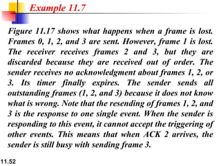
Figure 11.17 shows what happens when a frame is lost.
Frames 0, 1, 2, and 3 are sent. However, frame 1 is lost.
The receiver receives frames 2 and 3, but they are
discarded because they are received out of order. The
sender receives no acknowledgment about frames 1, 2, or
3. Its timer finally expires. The sender sends all
outstanding frames (1, 2, and 3) because it does not know
what is wrong. Note that the resending of frames 1, 2, and
3 is the response to one single event. When the sender is
responding to this event, it cannot accept the triggering of
other events. This means that when ACK 2 arrives, the
sender is still busy with sending frame 3.
Example 11.7
11.53
The physical layer must wait until this event is completed
and the data link layer goes back to its sleeping state. We
have shown a vertical line to indicate the delay. It is the
same story with ACK 3; but when ACK 3 arrives, the
sender is busy responding to ACK 2. It happens again
when ACK 4 arrives. Note that before the second timer
expires, all outstanding frames have been sent and the
timer is stopped.
Example 11.7 (continued)
11.54
Figure 11.17 Flow diagram for Example 11.7
11.55
Stop-and-Wait ARQ is a special case of
Go-Back-N ARQ in which the size of the
send window is 1.
Note
11.56
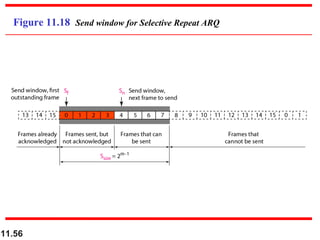
Figure 11.18 Send window for Selective Repeat ARQ
11.57
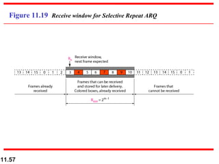
Figure 11.19 Receive window for Selective Repeat ARQ
11.58
Figure 11.20 Design of Selective Repeat ARQ
11.59
Figure 11.21 Selective Repeat ARQ, window size
11.60
In Selective Repeat ARQ, the size of the
sender and receiver window
must be at most one-half of 2m
.
Note
11.61
Algorithm 11.9 Sender-site Selective Repeat algorithm
(continued)
11.62
Algorithm 11.9 Sender-site Selective Repeat algorithm (continued)
(continued)
11.63
Algorithm 11.9 Sender-site Selective Repeat algorithm (continued)
11.64
Algorithm 11.10 Receiver-site Selective Repeat algorithm
11.65
Algorithm 11.10 Receiver-site Selective Repeat algorithm
11.66
Figure 11.22 Delivery of data in Selective Repeat ARQ
11.67
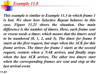
This example is similar to Example 11.3 in which frame 1
is lost. We show how Selective Repeat behaves in this
case. Figure 11.23 shows the situation. One main
difference is the number of timers. Here, each frame sent
or resent needs a timer, which means that the timers need
to be numbered (0, 1, 2, and 3). The timer for frame 0
starts at the first request, but stops when the ACK for this
frame arrives. The timer for frame 1 starts at the second
request, restarts when a NAK arrives, and finally stops
when the last ACK arrives. The other two timers start
when the corresponding frames are sent and stop at the
last arrival event.
Example 11.8
11.68
At the receiver site we need to distinguish between the
acceptance of a frame and its delivery to the network
layer. At the second arrival, frame 2 arrives and is stored
and marked, but it cannot be delivered because frame 1 is
missing. At the next arrival, frame 3 arrives and is
marked and stored, but still none of the frames can be
delivered. Only at the last arrival, when finally a copy of
frame 1 arrives, can frames 1, 2, and 3 be delivered to the
network layer. There are two conditions for the delivery
of frames to the network layer: First, a set of consecutive
frames must have arrived. Second, the set starts from the
beginning of the window.
Example 11.8 (continued)
11.69
Another important point is that a NAK is sent after the
second arrival, but not after the third, although both
situations look the same. The reason is that the protocol
does not want to crowd the network with unnecessary
NAKs and unnecessary resent frames. The second NAK
would still be NAK1 to inform the sender to resend frame
1 again; this has already been done. The first NAK sent is
remembered (using the nakSent variable) and is not sent
again until the frame slides. A NAK is sent once for each
window position and defines the first slot in the window.
Example 11.8 (continued)
11.70
The next point is about the ACKs. Notice that only two
ACKs are sent here. The first one acknowledges only the
first frame; the second one acknowledges three frames. In
Selective Repeat, ACKs are sent when data are delivered to
the network layer. If the data belonging to n frames are
delivered in one shot, only one ACK is sent for all of them.
Example 11.8 (continued)
11.71
Figure 11.23 Flow diagram for Example 11.8
11.72
Figure 11.24 Design of piggybacking in Go-Back-N ARQ
11.73
11-6 HDLC11-6 HDLC
High-level Data Link Control (HDLC)High-level Data Link Control (HDLC) is ais a bit-orientedbit-oriented
protocol for communication over point-to-point andprotocol for communication over point-to-point and
multipoint links. It implements the ARQ mechanismsmultipoint links. It implements the ARQ mechanisms
we discussed in this chapter.we discussed in this chapter.
Configurations and Transfer Modes
Frames
Control Field
Topics discussed in this section:Topics discussed in this section:
11.74
Figure 11.25 Normal response mode
11.75
Figure 11.26 Asynchronous balanced mode
11.76
Figure 11.27 HDLC frames
11.77
Figure 11.28 Control field format for the different frame types
11.78
Table 11.1 U-frame control command and response
11.79
Figure 11.29 shows how U-frames can be used for
connection establishment and connection release. Node A
asks for a connection with a set asynchronous balanced
mode (SABM) frame; node B gives a positive response
with an unnumbered acknowledgment (UA) frame. After
these two exchanges, data can be transferred between the
two nodes (not shown in the figure). After data transfer,
node A sends a DISC (disconnect) frame to release the
connection; it is confirmed by node B responding with a
UA (unnumbered acknowledgment).
Example 11.9
11.80
Figure 11.29 Example of connection and disconnection
11.81
Figure 11.30 shows an exchange using piggybacking.
Node A begins the exchange of information with an
I-frame numbered 0 followed by another I-frame
numbered 1. Node B piggybacks its acknowledgment of
both frames onto an I-frame of its own. Node B’s first
I-frame is also numbered 0 [N(S) field] and contains a 2
in its N(R) field, acknowledging the receipt of A’s frames
1 and 0 and indicating that it expects frame 2 to arrive
next. Node B transmits its second and third I-frames
(numbered 1 and 2) before accepting further frames from
node A.
Example 11.10
11.82
Its N(R) information, therefore, has not changed: B
frames 1 and 2 indicate that node B is still expecting A’s
frame 2 to arrive next. Node A has sent all its data.
Therefore, it cannot piggyback an acknowledgment onto
an I-frame and sends an S-frame instead. The RR code
indicates that A is still ready to receive. The number 3 in
the N(R) field tells B that frames 0, 1, and 2 have all been
accepted and that A is now expecting frame number 3.
Example 11.10 (continued)
11.83
Figure 11.30 Example of piggybacking without error
11.84
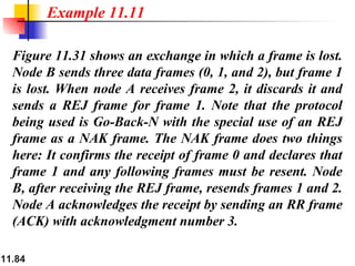
Figure 11.31 shows an exchange in which a frame is lost.
Node B sends three data frames (0, 1, and 2), but frame 1
is lost. When node A receives frame 2, it discards it and
sends a REJ frame for frame 1. Note that the protocol
being used is Go-Back-N with the special use of an REJ
frame as a NAK frame. The NAK frame does two things
here: It confirms the receipt of frame 0 and declares that
frame 1 and any following frames must be resent. Node
B, after receiving the REJ frame, resends frames 1 and 2.
Node A acknowledges the receipt by sending an RR frame
(ACK) with acknowledgment number 3.
Example 11.11
11.85
Figure 11.31 Example of piggybacking with error
11.86
11-7 POINT-TO-POINT PROTOCOL11-7 POINT-TO-POINT PROTOCOL
Although HDLC is a general protocol that can be usedAlthough HDLC is a general protocol that can be used
for both point-to-point and multipoint configurations,for both point-to-point and multipoint configurations,
one of the most common protocols for point-to-pointone of the most common protocols for point-to-point
access is theaccess is the Point-to-Point Protocol (PPP).Point-to-Point Protocol (PPP). PPP is aPPP is a
byte-orientedbyte-oriented protocol.protocol.
Framing
Transition Phases
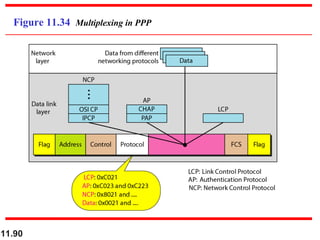
Multiplexing
Multilink PPP
Topics discussed in this section:Topics discussed in this section:
11.87
Figure 11.32 PPP frame format
11.88
PPP is a byte-oriented protocol using
byte stuffing with the escape byte
01111101.
Note
11.89
Figure 11.33 Transition phases
11.90
Figure 11.34 Multiplexing in PPP
11.91
Figure 11.35 LCP packet encapsulated in a frame
11.92
Table 11.2 LCP packets
11.93
Table 11.3 Common options
11.94
Figure 11.36 PAP packets encapsulated in a PPP frame
11.95
Figure 11.37 CHAP packets encapsulated in a PPP frame
11.96
Figure 11.38 IPCP packet encapsulated in PPP frame
11.97
Table 11.4 Code value for IPCP packets
11.98
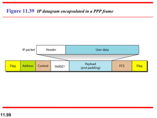
Figure 11.39 IP datagram encapsulated in a PPP frame
11.99
Figure 11.40 Multilink PPP
11.100
Let us go through the phases followed by a network layer
packet as it is transmitted through a PPP connection.
Figure 11.41 shows the steps. For simplicity, we assume
unidirectional movement of data from the user site to the
system site (such as sending an e-mail through an ISP).
The first two frames show link establishment. We have
chosen two options (not shown in the figure): using PAP
for authentication and suppressing the address control
fields. Frames 3 and 4 are for authentication. Frames 5
and 6 establish the network layer connection using IPCP.
Example 11.12
11.101
The next several frames show that some IP packets are
encapsulated in the PPP frame. The system (receiver)
may have been running several network layer protocols,
but it knows that the incoming data must be delivered to
the IP protocol because the NCP protocol used before the
data transfer was IPCP.
After data transfer, the user then terminates the data link
connection, which is acknowledged by the system. Of
course the user or the system could have chosen to
terminate the network layer IPCP and keep the data link
layer running if it wanted to run another NCP protocol.
Example 11.12 (continued)
11.102
Figure 11.41 An example
11.103
Figure 11.41 An example (continued)

More Related Content

What's hot

Chapter 4 data link layer
Chapter 4 data link layerChapter 4 data link layer
Chapter 4 data link layerNaiyan Noor
 
Unit 2 data link control
Unit 2 data link controlUnit 2 data link control
Unit 2 data link controlVishal kakade
 
4c Address Mapping, Error Reporting and Multicasting
4c Address Mapping, Error Reporting and Multicasting4c Address Mapping, Error Reporting and Multicasting
4c Address Mapping, Error Reporting and Multicastingkavish dani
 
Unit 4 data link layer
Unit 4 data link layerUnit 4 data link layer
Unit 4 data link layermekind
 
23 Process to_Process_Delivery_UDP_TCP_and_SCTP
23 Process to_Process_Delivery_UDP_TCP_and_SCTP23 Process to_Process_Delivery_UDP_TCP_and_SCTP
23 Process to_Process_Delivery_UDP_TCP_and_SCTPAhmar Hashmi
 
data-link layer protocols
data-link layer protocols  data-link layer protocols
data-link layer protocols BE Smârt
 
New framing-protocols
New framing-protocolsNew framing-protocols
New framing-protocolsNitesh Singh
 
Chapter 7 - Data Link Control Protocols 9e
Chapter 7 - Data Link Control Protocols 9eChapter 7 - Data Link Control Protocols 9e
Chapter 7 - Data Link Control Protocols 9eadpeer
 
A Survey of Different Approaches for Differentiating Bit Error and Congestion...
A Survey of Different Approaches for Differentiating Bit Error and Congestion...A Survey of Different Approaches for Differentiating Bit Error and Congestion...
A Survey of Different Approaches for Differentiating Bit Error and Congestion...IJERD Editor
 
13 Wired Lans_Ethernet
13 Wired Lans_Ethernet13 Wired Lans_Ethernet
13 Wired Lans_EthernetAhmar Hashmi
 

What's hot (20)

Ch21
Ch21Ch21
Ch21
 
Chapter 4 data link layer
Chapter 4 data link layerChapter 4 data link layer
Chapter 4 data link layer
 
Unit 2 data link control
Unit 2 data link controlUnit 2 data link control
Unit 2 data link control
 
08 Switching
08 Switching08 Switching
08 Switching
 
Ch23
Ch23Ch23
Ch23
 
4c Address Mapping, Error Reporting and Multicasting
4c Address Mapping, Error Reporting and Multicasting4c Address Mapping, Error Reporting and Multicasting
4c Address Mapping, Error Reporting and Multicasting
 
Unit 4 data link layer
Unit 4 data link layerUnit 4 data link layer
Unit 4 data link layer
 
Lect21 09-11
Lect21 09-11Lect21 09-11
Lect21 09-11
 
Ch11
Ch11Ch11
Ch11
 
Chapter 11
Chapter 11Chapter 11
Chapter 11
 
23 Process to_Process_Delivery_UDP_TCP_and_SCTP
23 Process to_Process_Delivery_UDP_TCP_and_SCTP23 Process to_Process_Delivery_UDP_TCP_and_SCTP
23 Process to_Process_Delivery_UDP_TCP_and_SCTP
 
Ch13
Ch13Ch13
Ch13
 
data-link layer protocols
data-link layer protocols  data-link layer protocols
data-link layer protocols
 
Ch28
Ch28Ch28
Ch28
 
New framing-protocols
New framing-protocolsNew framing-protocols
New framing-protocols
 
Unit 3 - Data Link Layer - Part B
Unit 3 - Data Link Layer - Part BUnit 3 - Data Link Layer - Part B
Unit 3 - Data Link Layer - Part B
 
Chapter 7 - Data Link Control Protocols 9e
Chapter 7 - Data Link Control Protocols 9eChapter 7 - Data Link Control Protocols 9e
Chapter 7 - Data Link Control Protocols 9e
 
A Survey of Different Approaches for Differentiating Bit Error and Congestion...
A Survey of Different Approaches for Differentiating Bit Error and Congestion...A Survey of Different Approaches for Differentiating Bit Error and Congestion...
A Survey of Different Approaches for Differentiating Bit Error and Congestion...
 
Ch22
Ch22Ch22
Ch22
 
13 Wired Lans_Ethernet
13 Wired Lans_Ethernet13 Wired Lans_Ethernet
13 Wired Lans_Ethernet
 

Viewers also liked

14 data link control
14 data link control14 data link control
14 data link controlarvindsarja
 
Encoding Video for the Web - Webinar from ReelSEO.com
Encoding Video for the Web  - Webinar from ReelSEO.comEncoding Video for the Web  - Webinar from ReelSEO.com
Encoding Video for the Web - Webinar from ReelSEO.comMark Robertson ⏩
 
Overview of Modem
Overview of Modem Overview of Modem
Overview of Modem Kishan Patel
 
Error detection and correction, flow and error control and trasmission media
Error detection and correction, flow and error control and  trasmission mediaError detection and correction, flow and error control and  trasmission media
Error detection and correction, flow and error control and trasmission mediaPANKAJ333
 
Data Link Control in Data Communication DC20
Data Link Control in Data Communication DC20Data Link Control in Data Communication DC20
Data Link Control in Data Communication DC20koolkampus
 
Physical layer interface & standards
Physical layer interface & standardsPhysical layer interface & standards
Physical layer interface & standardsSrashti Vyas
 
Modem technology
Modem technologyModem technology
Modem technologyDhruv Patel
 
Multiplexing
MultiplexingMultiplexing
Multiplexingnimay1
 
Encoding in Data Communication DC8
Encoding in Data Communication DC8Encoding in Data Communication DC8
Encoding in Data Communication DC8koolkampus
 
HDLC(high level data link control)
HDLC(high level data link control)HDLC(high level data link control)
HDLC(high level data link control)Anand Biradar
 
Error Detection and Correction - Data link Layer
Error Detection and Correction - Data link LayerError Detection and Correction - Data link Layer
Error Detection and Correction - Data link LayerAbdullaziz Tagawy
 
Multiplexing and switching(TDM ,FDM, Data gram, circuit switching)
Multiplexing and switching(TDM ,FDM, Data gram, circuit switching)Multiplexing and switching(TDM ,FDM, Data gram, circuit switching)
Multiplexing and switching(TDM ,FDM, Data gram, circuit switching)Adil Mehmoood
 
Flow & Error Control
Flow & Error ControlFlow & Error Control
Flow & Error Controltameemyousaf
 
Digital modulation
Digital modulationDigital modulation
Digital modulationAnkur Kumar
 

Viewers also liked (20)

14 data link control
14 data link control14 data link control
14 data link control
 
Flow control main
Flow control mainFlow control main
Flow control main
 
Encoding Video for the Web - Webinar from ReelSEO.com
Encoding Video for the Web  - Webinar from ReelSEO.comEncoding Video for the Web  - Webinar from ReelSEO.com
Encoding Video for the Web - Webinar from ReelSEO.com
 
Lecture 20
Lecture 20Lecture 20
Lecture 20
 
Encoding Techniques
Encoding TechniquesEncoding Techniques
Encoding Techniques
 
Chapter 10
Chapter 10Chapter 10
Chapter 10
 
Overview of Modem
Overview of Modem Overview of Modem
Overview of Modem
 
Error detection and correction, flow and error control and trasmission media
Error detection and correction, flow and error control and  trasmission mediaError detection and correction, flow and error control and  trasmission media
Error detection and correction, flow and error control and trasmission media
 
Rs 232 interface
Rs 232 interfaceRs 232 interface
Rs 232 interface
 
rs-232
rs-232rs-232
rs-232
 
Data Link Control in Data Communication DC20
Data Link Control in Data Communication DC20Data Link Control in Data Communication DC20
Data Link Control in Data Communication DC20
 
Physical layer interface & standards
Physical layer interface & standardsPhysical layer interface & standards
Physical layer interface & standards
 
Modem technology
Modem technologyModem technology
Modem technology
 
Multiplexing
MultiplexingMultiplexing
Multiplexing
 
Encoding in Data Communication DC8
Encoding in Data Communication DC8Encoding in Data Communication DC8
Encoding in Data Communication DC8
 
HDLC(high level data link control)
HDLC(high level data link control)HDLC(high level data link control)
HDLC(high level data link control)
 
Error Detection and Correction - Data link Layer
Error Detection and Correction - Data link LayerError Detection and Correction - Data link Layer
Error Detection and Correction - Data link Layer
 
Multiplexing and switching(TDM ,FDM, Data gram, circuit switching)
Multiplexing and switching(TDM ,FDM, Data gram, circuit switching)Multiplexing and switching(TDM ,FDM, Data gram, circuit switching)
Multiplexing and switching(TDM ,FDM, Data gram, circuit switching)
 
Flow & Error Control
Flow & Error ControlFlow & Error Control
Flow & Error Control
 
Digital modulation
Digital modulationDigital modulation
Digital modulation
 

Similar to 11 Data Link_Control

3a data link layer
3a data link layer 3a data link layer
3a data link layer kavish dani
 
Unit I Data Link Control.ppt
Unit I Data Link Control.pptUnit I Data Link Control.ppt
Unit I Data Link Control.pptMSANDHYARANI3
 
chapter 11(Data link Control)in CN .ppt
chapter 11(Data link Control)in CN  .pptchapter 11(Data link Control)in CN  .ppt
chapter 11(Data link Control)in CN .pptanjubala996089
 
Framming data link layer
Framming data link layerFramming data link layer
Framming data link layerPREMAL GAJJAR
 
SYBSC IT COMPUTER NETWORKS UNIT III Data Link Control
SYBSC IT COMPUTER NETWORKS UNIT III Data Link ControlSYBSC IT COMPUTER NETWORKS UNIT III Data Link Control
SYBSC IT COMPUTER NETWORKS UNIT III Data Link ControlArti Parab Academics
 
DataLinkControl.ppt
DataLinkControl.pptDataLinkControl.ppt
DataLinkControl.pptMaddalaSeshu
 
Data link control.pdf
Data link control.pdfData link control.pdf
Data link control.pdfDhairyaGohil
 
Flow Control (1).ppt
Flow Control (1).pptFlow Control (1).ppt
Flow Control (1).pptsarthakgithub
 
Link-Level Flow and Error Control Chapter11
Link-Level Flow and Error Control Chapter11Link-Level Flow and Error Control Chapter11
Link-Level Flow and Error Control Chapter11daniel ayalew
 
3a data link layer continued
3a data link layer continued3a data link layer continued
3a data link layer continuedkavish dani
 
U2CH1Data Link Layerxxxxxxxxxxxxxxxxx.pptx
U2CH1Data Link Layerxxxxxxxxxxxxxxxxx.pptxU2CH1Data Link Layerxxxxxxxxxxxxxxxxx.pptx
U2CH1Data Link Layerxxxxxxxxxxxxxxxxx.pptxk2w9psdb96
 
09 Data Link LayerFlow Control.ppt
09 Data Link LayerFlow Control.ppt09 Data Link LayerFlow Control.ppt
09 Data Link LayerFlow Control.pptShaliniKumariGupta1
 

Similar to 11 Data Link_Control (20)

3a data link layer
3a data link layer 3a data link layer
3a data link layer
 
Unit I Data Link Control.ppt
Unit I Data Link Control.pptUnit I Data Link Control.ppt
Unit I Data Link Control.ppt
 
chapter 11(Data link Control)in CN .ppt
chapter 11(Data link Control)in CN  .pptchapter 11(Data link Control)in CN  .ppt
chapter 11(Data link Control)in CN .ppt
 
dl_frames.ppt
dl_frames.pptdl_frames.ppt
dl_frames.ppt
 
Data Link Control.ppt
Data Link Control.pptData Link Control.ppt
Data Link Control.ppt
 
DLL Part_1.ppt
DLL Part_1.pptDLL Part_1.ppt
DLL Part_1.ppt
 
Framming data link layer
Framming data link layerFramming data link layer
Framming data link layer
 
Ch11
Ch11Ch11
Ch11
 
SYBSC IT COMPUTER NETWORKS UNIT III Data Link Control
SYBSC IT COMPUTER NETWORKS UNIT III Data Link ControlSYBSC IT COMPUTER NETWORKS UNIT III Data Link Control
SYBSC IT COMPUTER NETWORKS UNIT III Data Link Control
 
Ch11
Ch11Ch11
Ch11
 
DataLinkControl.ppt
DataLinkControl.pptDataLinkControl.ppt
DataLinkControl.ppt
 
Ch 11
Ch 11Ch 11
Ch 11
 
Data link control.pdf
Data link control.pdfData link control.pdf
Data link control.pdf
 
Flow Control (1).ppt
Flow Control (1).pptFlow Control (1).ppt
Flow Control (1).ppt
 
Link-Level Flow and Error Control Chapter11
Link-Level Flow and Error Control Chapter11Link-Level Flow and Error Control Chapter11
Link-Level Flow and Error Control Chapter11
 
3a data link layer continued
3a data link layer continued3a data link layer continued
3a data link layer continued
 
stop and wait
stop and waitstop and wait
stop and wait
 
U2CH1Data Link Layerxxxxxxxxxxxxxxxxx.pptx
U2CH1Data Link Layerxxxxxxxxxxxxxxxxx.pptxU2CH1Data Link Layerxxxxxxxxxxxxxxxxx.pptx
U2CH1Data Link Layerxxxxxxxxxxxxxxxxx.pptx
 
09 Data Link LayerFlow Control.ppt
09 Data Link LayerFlow Control.ppt09 Data Link LayerFlow Control.ppt
09 Data Link LayerFlow Control.ppt
 
Data link control
Data link controlData link control
Data link control
 

More from Ahmar Hashmi

32 Security in_Internet_IP_SEC_SSL/TLS_PGN_VPN_and_Firewalls
32 Security in_Internet_IP_SEC_SSL/TLS_PGN_VPN_and_Firewalls32 Security in_Internet_IP_SEC_SSL/TLS_PGN_VPN_and_Firewalls
32 Security in_Internet_IP_SEC_SSL/TLS_PGN_VPN_and_FirewallsAhmar Hashmi
 
31 Network Security
31 Network Security31 Network Security
31 Network SecurityAhmar Hashmi
 
28 Network Management_SNMP
28 Network Management_SNMP28 Network Management_SNMP
28 Network Management_SNMPAhmar Hashmi
 
26 Remote Logging_Electronic_Mail_and_File_Transfer
26 Remote Logging_Electronic_Mail_and_File_Transfer26 Remote Logging_Electronic_Mail_and_File_Transfer
26 Remote Logging_Electronic_Mail_and_File_TransferAhmar Hashmi
 
24 Congestion Control_and_Quality_of_Service
24 Congestion Control_and_Quality_of_Service24 Congestion Control_and_Quality_of_Service
24 Congestion Control_and_Quality_of_ServiceAhmar Hashmi
 
22 Network Layer_Delivery_forwarding_and_Routing
22 Network Layer_Delivery_forwarding_and_Routing22 Network Layer_Delivery_forwarding_and_Routing
22 Network Layer_Delivery_forwarding_and_RoutingAhmar Hashmi
 
20 Network Layer_Internet_Protocol
20 Network Layer_Internet_Protocol20 Network Layer_Internet_Protocol
20 Network Layer_Internet_ProtocolAhmar Hashmi
 
19 Network Layer_Logical_Addressing
19 Network Layer_Logical_Addressing19 Network Layer_Logical_Addressing
19 Network Layer_Logical_AddressingAhmar Hashmi
 
18 Virtual Circuit_Networks_Frame_Relay_and_ATM
18 Virtual Circuit_Networks_Frame_Relay_and_ATM18 Virtual Circuit_Networks_Frame_Relay_and_ATM
18 Virtual Circuit_Networks_Frame_Relay_and_ATMAhmar Hashmi
 
16 Wireless WANs_Cellular_Telephone_and_Satellite_Networks
16 Wireless WANs_Cellular_Telephone_and_Satellite_Networks16 Wireless WANs_Cellular_Telephone_and_Satellite_Networks
16 Wireless WANs_Cellular_Telephone_and_Satellite_NetworksAhmar Hashmi
 
15 Connecting LANs_Backbone_Networks_and_Virtual_LAN
15 Connecting LANs_Backbone_Networks_and_Virtual_LAN15 Connecting LANs_Backbone_Networks_and_Virtual_LAN
15 Connecting LANs_Backbone_Networks_and_Virtual_LANAhmar Hashmi
 
10 Error Detection_and_Correction
10 Error Detection_and_Correction10 Error Detection_and_Correction
10 Error Detection_and_CorrectionAhmar Hashmi
 
09 Using Telephone_and_Cable_Networks_for_Data_Transmission
09 Using Telephone_and_Cable_Networks_for_Data_Transmission09 Using Telephone_and_Cable_Networks_for_Data_Transmission
09 Using Telephone_and_Cable_Networks_for_Data_TransmissionAhmar Hashmi
 
07 Transmission Media
07 Transmission Media07 Transmission Media
07 Transmission MediaAhmar Hashmi
 

More from Ahmar Hashmi (20)

32 Security in_Internet_IP_SEC_SSL/TLS_PGN_VPN_and_Firewalls
32 Security in_Internet_IP_SEC_SSL/TLS_PGN_VPN_and_Firewalls32 Security in_Internet_IP_SEC_SSL/TLS_PGN_VPN_and_Firewalls
32 Security in_Internet_IP_SEC_SSL/TLS_PGN_VPN_and_Firewalls
 
31 Network Security
31 Network Security31 Network Security
31 Network Security
 
30 Cryptography
30 Cryptography30 Cryptography
30 Cryptography
 
29 Multimedia
29 Multimedia29 Multimedia
29 Multimedia
 
28 Network Management_SNMP
28 Network Management_SNMP28 Network Management_SNMP
28 Network Management_SNMP
 
27 WWW and_HTTP
27 WWW and_HTTP27 WWW and_HTTP
27 WWW and_HTTP
 
26 Remote Logging_Electronic_Mail_and_File_Transfer
26 Remote Logging_Electronic_Mail_and_File_Transfer26 Remote Logging_Electronic_Mail_and_File_Transfer
26 Remote Logging_Electronic_Mail_and_File_Transfer
 
25 DNS
25 DNS25 DNS
25 DNS
 
24 Congestion Control_and_Quality_of_Service
24 Congestion Control_and_Quality_of_Service24 Congestion Control_and_Quality_of_Service
24 Congestion Control_and_Quality_of_Service
 
22 Network Layer_Delivery_forwarding_and_Routing
22 Network Layer_Delivery_forwarding_and_Routing22 Network Layer_Delivery_forwarding_and_Routing
22 Network Layer_Delivery_forwarding_and_Routing
 
20 Network Layer_Internet_Protocol
20 Network Layer_Internet_Protocol20 Network Layer_Internet_Protocol
20 Network Layer_Internet_Protocol
 
19 Network Layer_Logical_Addressing
19 Network Layer_Logical_Addressing19 Network Layer_Logical_Addressing
19 Network Layer_Logical_Addressing
 
18 Virtual Circuit_Networks_Frame_Relay_and_ATM
18 Virtual Circuit_Networks_Frame_Relay_and_ATM18 Virtual Circuit_Networks_Frame_Relay_and_ATM
18 Virtual Circuit_Networks_Frame_Relay_and_ATM
 
17 SONET/SDH
17 SONET/SDH17 SONET/SDH
17 SONET/SDH
 
16 Wireless WANs_Cellular_Telephone_and_Satellite_Networks
16 Wireless WANs_Cellular_Telephone_and_Satellite_Networks16 Wireless WANs_Cellular_Telephone_and_Satellite_Networks
16 Wireless WANs_Cellular_Telephone_and_Satellite_Networks
 
15 Connecting LANs_Backbone_Networks_and_Virtual_LAN
15 Connecting LANs_Backbone_Networks_and_Virtual_LAN15 Connecting LANs_Backbone_Networks_and_Virtual_LAN
15 Connecting LANs_Backbone_Networks_and_Virtual_LAN
 
14 Wireless LAN
14 Wireless LAN14 Wireless LAN
14 Wireless LAN
 
10 Error Detection_and_Correction
10 Error Detection_and_Correction10 Error Detection_and_Correction
10 Error Detection_and_Correction
 
09 Using Telephone_and_Cable_Networks_for_Data_Transmission
09 Using Telephone_and_Cable_Networks_for_Data_Transmission09 Using Telephone_and_Cable_Networks_for_Data_Transmission
09 Using Telephone_and_Cable_Networks_for_Data_Transmission
 
07 Transmission Media
07 Transmission Media07 Transmission Media
07 Transmission Media
 

Recently uploaded

Sanyam Choudhary Chemistry practical.pdf
Sanyam Choudhary Chemistry practical.pdfSanyam Choudhary Chemistry practical.pdf
Sanyam Choudhary Chemistry practical.pdfsanyamsingh5019
 
Mastering the Unannounced Regulatory Inspection
Mastering the Unannounced Regulatory InspectionMastering the Unannounced Regulatory Inspection
Mastering the Unannounced Regulatory InspectionSafetyChain Software
 
microwave assisted reaction. General introduction
microwave assisted reaction. General introductionmicrowave assisted reaction. General introduction
microwave assisted reaction. General introductionMaksud Ahmed
 
Kisan Call Centre - To harness potential of ICT in Agriculture by answer farm...
Kisan Call Centre - To harness potential of ICT in Agriculture by answer farm...Kisan Call Centre - To harness potential of ICT in Agriculture by answer farm...
Kisan Call Centre - To harness potential of ICT in Agriculture by answer farm...Krashi Coaching
 
Incoming and Outgoing Shipments in 1 STEP Using Odoo 17
Incoming and Outgoing Shipments in 1 STEP Using Odoo 17Incoming and Outgoing Shipments in 1 STEP Using Odoo 17
Incoming and Outgoing Shipments in 1 STEP Using Odoo 17Celine George
 
Call Girls in Dwarka Mor Delhi Contact Us 9654467111
Call Girls in Dwarka Mor Delhi Contact Us 9654467111Call Girls in Dwarka Mor Delhi Contact Us 9654467111
Call Girls in Dwarka Mor Delhi Contact Us 9654467111Sapana Sha
 
Introduction to AI in Higher Education_draft.pptx
Introduction to AI in Higher Education_draft.pptxIntroduction to AI in Higher Education_draft.pptx
Introduction to AI in Higher Education_draft.pptxpboyjonauth
 
Crayon Activity Handout For the Crayon A
Crayon Activity Handout For the Crayon ACrayon Activity Handout For the Crayon A
Crayon Activity Handout For the Crayon AUnboundStockton
 
Presiding Officer Training module 2024 lok sabha elections
Presiding Officer Training module 2024 lok sabha electionsPresiding Officer Training module 2024 lok sabha elections
Presiding Officer Training module 2024 lok sabha electionsanshu789521
 
Presentation by Andreas Schleicher Tackling the School Absenteeism Crisis 30 ...
Presentation by Andreas Schleicher Tackling the School Absenteeism Crisis 30 ...Presentation by Andreas Schleicher Tackling the School Absenteeism Crisis 30 ...
Presentation by Andreas Schleicher Tackling the School Absenteeism Crisis 30 ...EduSkills OECD
 
Organic Name Reactions for the students and aspirants of Chemistry12th.pptx
Organic Name Reactions  for the students and aspirants of Chemistry12th.pptxOrganic Name Reactions  for the students and aspirants of Chemistry12th.pptx
Organic Name Reactions for the students and aspirants of Chemistry12th.pptxVS Mahajan Coaching Centre
 
Q4-W6-Restating Informational Text Grade 3
Q4-W6-Restating Informational Text Grade 3Q4-W6-Restating Informational Text Grade 3
Q4-W6-Restating Informational Text Grade 3JemimahLaneBuaron
 
How to Make a Pirate ship Primary Education.pptx
How to Make a Pirate ship Primary Education.pptxHow to Make a Pirate ship Primary Education.pptx
How to Make a Pirate ship Primary Education.pptxmanuelaromero2013
 
Industrial Policy - 1948, 1956, 1973, 1977, 1980, 1991
Industrial Policy - 1948, 1956, 1973, 1977, 1980, 1991Industrial Policy - 1948, 1956, 1973, 1977, 1980, 1991
Industrial Policy - 1948, 1956, 1973, 1977, 1980, 1991RKavithamani
 
BASLIQ CURRENT LOOKBOOK LOOKBOOK(1) (1).pdf
BASLIQ CURRENT LOOKBOOK  LOOKBOOK(1) (1).pdfBASLIQ CURRENT LOOKBOOK  LOOKBOOK(1) (1).pdf
BASLIQ CURRENT LOOKBOOK LOOKBOOK(1) (1).pdfSoniaTolstoy
 
Introduction to ArtificiaI Intelligence in Higher Education
Introduction to ArtificiaI Intelligence in Higher EducationIntroduction to ArtificiaI Intelligence in Higher Education
Introduction to ArtificiaI Intelligence in Higher Educationpboyjonauth
 
18-04-UA_REPORT_MEDIALITERAСY_INDEX-DM_23-1-final-eng.pdf
18-04-UA_REPORT_MEDIALITERAСY_INDEX-DM_23-1-final-eng.pdf18-04-UA_REPORT_MEDIALITERAСY_INDEX-DM_23-1-final-eng.pdf
18-04-UA_REPORT_MEDIALITERAСY_INDEX-DM_23-1-final-eng.pdfssuser54595a
 
Employee wellbeing at the workplace.pptx
Employee wellbeing at the workplace.pptxEmployee wellbeing at the workplace.pptx
Employee wellbeing at the workplace.pptxNirmalaLoungPoorunde1
 
PSYCHIATRIC History collection FORMAT.pptx
PSYCHIATRIC   History collection FORMAT.pptxPSYCHIATRIC   History collection FORMAT.pptx
PSYCHIATRIC History collection FORMAT.pptxPoojaSen20
 

Recently uploaded (20)

Sanyam Choudhary Chemistry practical.pdf
Sanyam Choudhary Chemistry practical.pdfSanyam Choudhary Chemistry practical.pdf
Sanyam Choudhary Chemistry practical.pdf
 
Mastering the Unannounced Regulatory Inspection
Mastering the Unannounced Regulatory InspectionMastering the Unannounced Regulatory Inspection
Mastering the Unannounced Regulatory Inspection
 
microwave assisted reaction. General introduction
microwave assisted reaction. General introductionmicrowave assisted reaction. General introduction
microwave assisted reaction. General introduction
 
Kisan Call Centre - To harness potential of ICT in Agriculture by answer farm...
Kisan Call Centre - To harness potential of ICT in Agriculture by answer farm...Kisan Call Centre - To harness potential of ICT in Agriculture by answer farm...
Kisan Call Centre - To harness potential of ICT in Agriculture by answer farm...
 
Incoming and Outgoing Shipments in 1 STEP Using Odoo 17
Incoming and Outgoing Shipments in 1 STEP Using Odoo 17Incoming and Outgoing Shipments in 1 STEP Using Odoo 17
Incoming and Outgoing Shipments in 1 STEP Using Odoo 17
 
Call Girls in Dwarka Mor Delhi Contact Us 9654467111
Call Girls in Dwarka Mor Delhi Contact Us 9654467111Call Girls in Dwarka Mor Delhi Contact Us 9654467111
Call Girls in Dwarka Mor Delhi Contact Us 9654467111
 
Introduction to AI in Higher Education_draft.pptx
Introduction to AI in Higher Education_draft.pptxIntroduction to AI in Higher Education_draft.pptx
Introduction to AI in Higher Education_draft.pptx
 
Crayon Activity Handout For the Crayon A
Crayon Activity Handout For the Crayon ACrayon Activity Handout For the Crayon A
Crayon Activity Handout For the Crayon A
 
Presiding Officer Training module 2024 lok sabha elections
Presiding Officer Training module 2024 lok sabha electionsPresiding Officer Training module 2024 lok sabha elections
Presiding Officer Training module 2024 lok sabha elections
 
Presentation by Andreas Schleicher Tackling the School Absenteeism Crisis 30 ...
Presentation by Andreas Schleicher Tackling the School Absenteeism Crisis 30 ...Presentation by Andreas Schleicher Tackling the School Absenteeism Crisis 30 ...
Presentation by Andreas Schleicher Tackling the School Absenteeism Crisis 30 ...
 
Organic Name Reactions for the students and aspirants of Chemistry12th.pptx
Organic Name Reactions  for the students and aspirants of Chemistry12th.pptxOrganic Name Reactions  for the students and aspirants of Chemistry12th.pptx
Organic Name Reactions for the students and aspirants of Chemistry12th.pptx
 
Q4-W6-Restating Informational Text Grade 3
Q4-W6-Restating Informational Text Grade 3Q4-W6-Restating Informational Text Grade 3
Q4-W6-Restating Informational Text Grade 3
 
How to Make a Pirate ship Primary Education.pptx
How to Make a Pirate ship Primary Education.pptxHow to Make a Pirate ship Primary Education.pptx
How to Make a Pirate ship Primary Education.pptx
 
Industrial Policy - 1948, 1956, 1973, 1977, 1980, 1991
Industrial Policy - 1948, 1956, 1973, 1977, 1980, 1991Industrial Policy - 1948, 1956, 1973, 1977, 1980, 1991
Industrial Policy - 1948, 1956, 1973, 1977, 1980, 1991
 
Model Call Girl in Bikash Puri Delhi reach out to us at 🔝9953056974🔝
Model Call Girl in Bikash Puri  Delhi reach out to us at 🔝9953056974🔝Model Call Girl in Bikash Puri  Delhi reach out to us at 🔝9953056974🔝
Model Call Girl in Bikash Puri Delhi reach out to us at 🔝9953056974🔝
 
BASLIQ CURRENT LOOKBOOK LOOKBOOK(1) (1).pdf
BASLIQ CURRENT LOOKBOOK  LOOKBOOK(1) (1).pdfBASLIQ CURRENT LOOKBOOK  LOOKBOOK(1) (1).pdf
BASLIQ CURRENT LOOKBOOK LOOKBOOK(1) (1).pdf
 
Introduction to ArtificiaI Intelligence in Higher Education
Introduction to ArtificiaI Intelligence in Higher EducationIntroduction to ArtificiaI Intelligence in Higher Education
Introduction to ArtificiaI Intelligence in Higher Education
 
18-04-UA_REPORT_MEDIALITERAСY_INDEX-DM_23-1-final-eng.pdf
18-04-UA_REPORT_MEDIALITERAСY_INDEX-DM_23-1-final-eng.pdf18-04-UA_REPORT_MEDIALITERAСY_INDEX-DM_23-1-final-eng.pdf
18-04-UA_REPORT_MEDIALITERAСY_INDEX-DM_23-1-final-eng.pdf
 
Employee wellbeing at the workplace.pptx
Employee wellbeing at the workplace.pptxEmployee wellbeing at the workplace.pptx
Employee wellbeing at the workplace.pptx
 
PSYCHIATRIC History collection FORMAT.pptx
PSYCHIATRIC   History collection FORMAT.pptxPSYCHIATRIC   History collection FORMAT.pptx
PSYCHIATRIC History collection FORMAT.pptx
 

11 Data Link_Control

  • 1. 11.1 Chapter 11 Data Link Control Copyright © The McGraw-Hill Companies, Inc. Permission required for reproduction or display.
  • 2. 11.2 11-1 FRAMING11-1 FRAMING The data link layer needs to pack bits intoThe data link layer needs to pack bits into framesframes, so, so that each frame is distinguishable from another. Ourthat each frame is distinguishable from another. Our postal system practices a type of framing. The simplepostal system practices a type of framing. The simple act of inserting a letter into an envelope separates oneact of inserting a letter into an envelope separates one piece of information from another; the envelope servespiece of information from another; the envelope serves as the delimiter.as the delimiter. Fixed-Size Framing Variable-Size Framing Topics discussed in this section:Topics discussed in this section:
  • 3. 11.3 Figure 11.1 A frame in a character-oriented protocol
  • 4. 11.4 Figure 11.2 Byte stuffing and unstuffing
  • 5. 11.5 Byte stuffing is the process of adding 1 extra byte whenever there is a flag or escape character in the text. Note
  • 6. 11.6 Figure 11.3 A frame in a bit-oriented protocol
  • 7. 11.7 Bit stuffing is the process of adding one extra 0 whenever five consecutive 1s follow a 0 in the data, so that the receiver does not mistake the pattern 0111110 for a flag. Note
  • 8. 11.8 Figure 11.4 Bit stuffing and unstuffing
  • 9. 11.9 11-2 FLOW AND ERROR CONTROL11-2 FLOW AND ERROR CONTROL The most important responsibilities of the data linkThe most important responsibilities of the data link layer arelayer are flow controlflow control andand error controlerror control. Collectively,. Collectively, these functions are known asthese functions are known as data link controldata link control.. Flow Control Error Control Topics discussed in this section:Topics discussed in this section:
  • 10. 11.10 Flow control refers to a set of procedures used to restrict the amount of data that the sender can send before waiting for acknowledgment. Note
  • 11. 11.11 Error control in the data link layer is based on automatic repeat request, which is the retransmission of data. Note
  • 12. 11.12 11-3 PROTOCOLS11-3 PROTOCOLS Now let us see how the data link layer can combineNow let us see how the data link layer can combine framing, flow control, and error control to achieve theframing, flow control, and error control to achieve the delivery of data from one node to another. Thedelivery of data from one node to another. The protocols are normally implemented in software byprotocols are normally implemented in software by using one of the common programming languages. Tousing one of the common programming languages. To make our discussions language-free, we have writtenmake our discussions language-free, we have written in pseudocode a version of each protocol thatin pseudocode a version of each protocol that concentrates mostly on the procedure instead ofconcentrates mostly on the procedure instead of delving into the details of language rules.delving into the details of language rules.
  • 13. 11.13 Figure 11.5 Taxonomy of protocols discussed in this chapter
  • 14. 11.14 11-4 NOISELESS CHANNELS11-4 NOISELESS CHANNELS Let us first assume we have an ideal channel in whichLet us first assume we have an ideal channel in which no frames are lost, duplicated, or corrupted. Weno frames are lost, duplicated, or corrupted. We introduce two protocols for this type of channel.introduce two protocols for this type of channel. Simplest Protocol Stop-and-Wait Protocol Topics discussed in this section:Topics discussed in this section:
  • 15. 11.15 Figure 11.6 The design of the simplest protocol with no flow or error control
  • 16. 11.16 Algorithm 11.1 Sender-site algorithm for the simplest protocol
  • 17. 11.17 Algorithm 11.2 Receiver-site algorithm for the simplest protocol
  • 18. 11.18 Figure 11.7 shows an example of communication using this protocol. It is very simple. The sender sends a sequence of frames without even thinking about the receiver. To send three frames, three events occur at the sender site and three events at the receiver site. Note that the data frames are shown by tilted boxes; the height of the box defines the transmission time difference between the first bit and the last bit in the frame. Example 11.1
  • 19. 11.19 Figure 11.7 Flow diagram for Example 11.1
  • 20. 11.20 Figure 11.8 Design of Stop-and-Wait Protocol
  • 21. 11.21 Algorithm 11.3 Sender-site algorithm for Stop-and-Wait Protocol
  • 22. 11.22 Algorithm 11.4 Receiver-site algorithm for Stop-and-Wait Protocol
  • 23. 11.23 Figure 11.9 shows an example of communication using this protocol. It is still very simple. The sender sends one frame and waits for feedback from the receiver. When the ACK arrives, the sender sends the next frame. Note that sending two frames in the protocol involves the sender in four events and the receiver in two events. Example 11.2
  • 24. 11.24 Figure 11.9 Flow diagram for Example 11.2
  • 25. 11.25 11-5 NOISY CHANNELS11-5 NOISY CHANNELS Although the Stop-and-Wait Protocol gives us an ideaAlthough the Stop-and-Wait Protocol gives us an idea of how to add flow control to its predecessor, noiselessof how to add flow control to its predecessor, noiseless channels are nonexistent. We discuss three protocolschannels are nonexistent. We discuss three protocols in this section that use error control.in this section that use error control. Stop-and-Wait Automatic Repeat Request Go-Back-N Automatic Repeat Request Selective Repeat Automatic Repeat Request Topics discussed in this section:Topics discussed in this section:
  • 26. 11.26 Error correction in Stop-and-Wait ARQ is done by keeping a copy of the sent frame and retransmitting of the frame when the timer expires. Note
  • 27. 11.27 In Stop-and-Wait ARQ, we use sequence numbers to number the frames. The sequence numbers are based on modulo-2 arithmetic. Note
  • 28. 11.28 In Stop-and-Wait ARQ, the acknowledgment number always announces in modulo-2 arithmetic the sequence number of the next frame expected. Note
  • 29. 11.29 Figure 11.10 Design of the Stop-and-Wait ARQ Protocol
  • 30. 11.30 Algorithm 11.5 Sender-site algorithm for Stop-and-Wait ARQ (continued)
  • 31. 11.31 Algorithm 11.5 Sender-site algorithm for Stop-and-Wait ARQ (continued)
  • 32. 11.32 Algorithm 11.6 Receiver-site algorithm for Stop-and-Wait ARQ Protocol
  • 33. 11.33 Figure 11.11 shows an example of Stop-and-Wait ARQ. Frame 0 is sent and acknowledged. Frame 1 is lost and resent after the time-out. The resent frame 1 is acknowledged and the timer stops. Frame 0 is sent and acknowledged, but the acknowledgment is lost. The sender has no idea if the frame or the acknowledgment is lost, so after the time-out, it resends frame 0, which is acknowledged. Example 11.3
  • 34. 11.34 Figure 11.11 Flow diagram for Example 11.3
  • 35. 11.35 Assume that, in a Stop-and-Wait ARQ system, the bandwidth of the line is 1 Mbps, and 1 bit takes 20 ms to make a round trip. What is the bandwidth-delay product? If the system data frames are 1000 bits in length, what is the utilization percentage of the link? Solution The bandwidth-delay product is Example 11.4
  • 36. 11.36 The system can send 20,000 bits during the time it takes for the data to go from the sender to the receiver and then back again. However, the system sends only 1000 bits. We can say that the link utilization is only 1000/20,000, or 5 percent. For this reason, for a link with a high bandwidth or long delay, the use of Stop-and-Wait ARQ wastes the capacity of the link. Example 11.4 (continued)
  • 37. 11.37 What is the utilization percentage of the link in Example 11.4 if we have a protocol that can send up to 15 frames before stopping and worrying about the acknowledgments? Solution The bandwidth-delay product is still 20,000 bits. The system can send up to 15 frames or 15,000 bits during a round trip. This means the utilization is 15,000/20,000, or 75 percent. Of course, if there are damaged frames, the utilization percentage is much less because frames have to be resent. Example 11.5
  • 38. 11.38 In the Go-Back-N Protocol, the sequence numbers are modulo 2m , where m is the size of the sequence number field in bits. Note
  • 39. 11.39 Figure 11.12 Send window for Go-Back-N ARQ
  • 40. 11.40 The send window is an abstract concept defining an imaginary box of size 2m − 1 with three variables: Sf, Sn, and Ssize. Note
  • 41. 11.41 The send window can slide one or more slots when a valid acknowledgment arrives. Note
  • 42. 11.42 Figure 11.13 Receive window for Go-Back-N ARQ
  • 43. 11.43 The receive window is an abstract concept defining an imaginary box of size 1 with one single variable Rn. The window slides when a correct frame has arrived; sliding occurs one slot at a time. Note
  • 44. 11.44 Figure 11.14 Design of Go-Back-N ARQ
  • 45. 11.45 Figure 11.15 Window size for Go-Back-N ARQ
  • 46. 11.46 In Go-Back-N ARQ, the size of the send window must be less than 2m ; the size of the receiver window is always 1. Note
  • 47. 11.47 Algorithm 11.7 Go-Back-N sender algorithm (continued)
  • 48. 11.48 Algorithm 11.7 Go-Back-N sender algorithm (continued)
  • 49. 11.49 Algorithm 11.8 Go-Back-N receiver algorithm
  • 50. 11.50 Example 11.6 Figure 11.16 shows an example of Go-Back-N. This is an example of a case where the forward channel is reliable, but the reverse is not. No data frames are lost, but some ACKs are delayed and one is lost. The example also shows how cumulative acknowledgments can help if acknowledgments are delayed or lost. After initialization, there are seven sender events. Request events are triggered by data from the network layer; arrival events are triggered by acknowledgments from the physical layer. There is no time-out event here because all outstanding frames are acknowledged before the timer expires. Note that although ACK 2 is lost, ACK 3 serves as both ACK 2 and ACK 3.
  • 51. 11.51 Figure 11.16 Flow diagram for Example 11.6
  • 52. 11.52 Figure 11.17 shows what happens when a frame is lost. Frames 0, 1, 2, and 3 are sent. However, frame 1 is lost. The receiver receives frames 2 and 3, but they are discarded because they are received out of order. The sender receives no acknowledgment about frames 1, 2, or 3. Its timer finally expires. The sender sends all outstanding frames (1, 2, and 3) because it does not know what is wrong. Note that the resending of frames 1, 2, and 3 is the response to one single event. When the sender is responding to this event, it cannot accept the triggering of other events. This means that when ACK 2 arrives, the sender is still busy with sending frame 3. Example 11.7
  • 53. 11.53 The physical layer must wait until this event is completed and the data link layer goes back to its sleeping state. We have shown a vertical line to indicate the delay. It is the same story with ACK 3; but when ACK 3 arrives, the sender is busy responding to ACK 2. It happens again when ACK 4 arrives. Note that before the second timer expires, all outstanding frames have been sent and the timer is stopped. Example 11.7 (continued)
  • 54. 11.54 Figure 11.17 Flow diagram for Example 11.7
  • 55. 11.55 Stop-and-Wait ARQ is a special case of Go-Back-N ARQ in which the size of the send window is 1. Note
  • 56. 11.56 Figure 11.18 Send window for Selective Repeat ARQ
  • 57. 11.57 Figure 11.19 Receive window for Selective Repeat ARQ
  • 58. 11.58 Figure 11.20 Design of Selective Repeat ARQ
  • 59. 11.59 Figure 11.21 Selective Repeat ARQ, window size
  • 60. 11.60 In Selective Repeat ARQ, the size of the sender and receiver window must be at most one-half of 2m . Note
  • 61. 11.61 Algorithm 11.9 Sender-site Selective Repeat algorithm (continued)
  • 62. 11.62 Algorithm 11.9 Sender-site Selective Repeat algorithm (continued) (continued)
  • 63. 11.63 Algorithm 11.9 Sender-site Selective Repeat algorithm (continued)
  • 64. 11.64 Algorithm 11.10 Receiver-site Selective Repeat algorithm
  • 65. 11.65 Algorithm 11.10 Receiver-site Selective Repeat algorithm
  • 66. 11.66 Figure 11.22 Delivery of data in Selective Repeat ARQ
  • 67. 11.67 This example is similar to Example 11.3 in which frame 1 is lost. We show how Selective Repeat behaves in this case. Figure 11.23 shows the situation. One main difference is the number of timers. Here, each frame sent or resent needs a timer, which means that the timers need to be numbered (0, 1, 2, and 3). The timer for frame 0 starts at the first request, but stops when the ACK for this frame arrives. The timer for frame 1 starts at the second request, restarts when a NAK arrives, and finally stops when the last ACK arrives. The other two timers start when the corresponding frames are sent and stop at the last arrival event. Example 11.8
  • 68. 11.68 At the receiver site we need to distinguish between the acceptance of a frame and its delivery to the network layer. At the second arrival, frame 2 arrives and is stored and marked, but it cannot be delivered because frame 1 is missing. At the next arrival, frame 3 arrives and is marked and stored, but still none of the frames can be delivered. Only at the last arrival, when finally a copy of frame 1 arrives, can frames 1, 2, and 3 be delivered to the network layer. There are two conditions for the delivery of frames to the network layer: First, a set of consecutive frames must have arrived. Second, the set starts from the beginning of the window. Example 11.8 (continued)
  • 69. 11.69 Another important point is that a NAK is sent after the second arrival, but not after the third, although both situations look the same. The reason is that the protocol does not want to crowd the network with unnecessary NAKs and unnecessary resent frames. The second NAK would still be NAK1 to inform the sender to resend frame 1 again; this has already been done. The first NAK sent is remembered (using the nakSent variable) and is not sent again until the frame slides. A NAK is sent once for each window position and defines the first slot in the window. Example 11.8 (continued)
  • 70. 11.70 The next point is about the ACKs. Notice that only two ACKs are sent here. The first one acknowledges only the first frame; the second one acknowledges three frames. In Selective Repeat, ACKs are sent when data are delivered to the network layer. If the data belonging to n frames are delivered in one shot, only one ACK is sent for all of them. Example 11.8 (continued)
  • 71. 11.71 Figure 11.23 Flow diagram for Example 11.8
  • 72. 11.72 Figure 11.24 Design of piggybacking in Go-Back-N ARQ
  • 73. 11.73 11-6 HDLC11-6 HDLC High-level Data Link Control (HDLC)High-level Data Link Control (HDLC) is ais a bit-orientedbit-oriented protocol for communication over point-to-point andprotocol for communication over point-to-point and multipoint links. It implements the ARQ mechanismsmultipoint links. It implements the ARQ mechanisms we discussed in this chapter.we discussed in this chapter. Configurations and Transfer Modes Frames Control Field Topics discussed in this section:Topics discussed in this section:
  • 74. 11.74 Figure 11.25 Normal response mode
  • 77. 11.77 Figure 11.28 Control field format for the different frame types
  • 78. 11.78 Table 11.1 U-frame control command and response
  • 79. 11.79 Figure 11.29 shows how U-frames can be used for connection establishment and connection release. Node A asks for a connection with a set asynchronous balanced mode (SABM) frame; node B gives a positive response with an unnumbered acknowledgment (UA) frame. After these two exchanges, data can be transferred between the two nodes (not shown in the figure). After data transfer, node A sends a DISC (disconnect) frame to release the connection; it is confirmed by node B responding with a UA (unnumbered acknowledgment). Example 11.9
  • 80. 11.80 Figure 11.29 Example of connection and disconnection
  • 81. 11.81 Figure 11.30 shows an exchange using piggybacking. Node A begins the exchange of information with an I-frame numbered 0 followed by another I-frame numbered 1. Node B piggybacks its acknowledgment of both frames onto an I-frame of its own. Node B’s first I-frame is also numbered 0 [N(S) field] and contains a 2 in its N(R) field, acknowledging the receipt of A’s frames 1 and 0 and indicating that it expects frame 2 to arrive next. Node B transmits its second and third I-frames (numbered 1 and 2) before accepting further frames from node A. Example 11.10
  • 82. 11.82 Its N(R) information, therefore, has not changed: B frames 1 and 2 indicate that node B is still expecting A’s frame 2 to arrive next. Node A has sent all its data. Therefore, it cannot piggyback an acknowledgment onto an I-frame and sends an S-frame instead. The RR code indicates that A is still ready to receive. The number 3 in the N(R) field tells B that frames 0, 1, and 2 have all been accepted and that A is now expecting frame number 3. Example 11.10 (continued)
  • 83. 11.83 Figure 11.30 Example of piggybacking without error
  • 84. 11.84 Figure 11.31 shows an exchange in which a frame is lost. Node B sends three data frames (0, 1, and 2), but frame 1 is lost. When node A receives frame 2, it discards it and sends a REJ frame for frame 1. Note that the protocol being used is Go-Back-N with the special use of an REJ frame as a NAK frame. The NAK frame does two things here: It confirms the receipt of frame 0 and declares that frame 1 and any following frames must be resent. Node B, after receiving the REJ frame, resends frames 1 and 2. Node A acknowledges the receipt by sending an RR frame (ACK) with acknowledgment number 3. Example 11.11
  • 85. 11.85 Figure 11.31 Example of piggybacking with error
  • 86. 11.86 11-7 POINT-TO-POINT PROTOCOL11-7 POINT-TO-POINT PROTOCOL Although HDLC is a general protocol that can be usedAlthough HDLC is a general protocol that can be used for both point-to-point and multipoint configurations,for both point-to-point and multipoint configurations, one of the most common protocols for point-to-pointone of the most common protocols for point-to-point access is theaccess is the Point-to-Point Protocol (PPP).Point-to-Point Protocol (PPP). PPP is aPPP is a byte-orientedbyte-oriented protocol.protocol. Framing Transition Phases Multiplexing Multilink PPP Topics discussed in this section:Topics discussed in this section:
  • 87. 11.87 Figure 11.32 PPP frame format
  • 88. 11.88 PPP is a byte-oriented protocol using byte stuffing with the escape byte 01111101. Note
  • 91. 11.91 Figure 11.35 LCP packet encapsulated in a frame
  • 94. 11.94 Figure 11.36 PAP packets encapsulated in a PPP frame
  • 95. 11.95 Figure 11.37 CHAP packets encapsulated in a PPP frame
  • 96. 11.96 Figure 11.38 IPCP packet encapsulated in PPP frame
  • 97. 11.97 Table 11.4 Code value for IPCP packets
  • 98. 11.98 Figure 11.39 IP datagram encapsulated in a PPP frame
  • 100. 11.100 Let us go through the phases followed by a network layer packet as it is transmitted through a PPP connection. Figure 11.41 shows the steps. For simplicity, we assume unidirectional movement of data from the user site to the system site (such as sending an e-mail through an ISP). The first two frames show link establishment. We have chosen two options (not shown in the figure): using PAP for authentication and suppressing the address control fields. Frames 3 and 4 are for authentication. Frames 5 and 6 establish the network layer connection using IPCP. Example 11.12
  • 101. 11.101 The next several frames show that some IP packets are encapsulated in the PPP frame. The system (receiver) may have been running several network layer protocols, but it knows that the incoming data must be delivered to the IP protocol because the NCP protocol used before the data transfer was IPCP. After data transfer, the user then terminates the data link connection, which is acknowledged by the system. Of course the user or the system could have chosen to terminate the network layer IPCP and keep the data link layer running if it wanted to run another NCP protocol. Example 11.12 (continued)
  • 103. 11.103 Figure 11.41 An example (continued)