Download to read offline
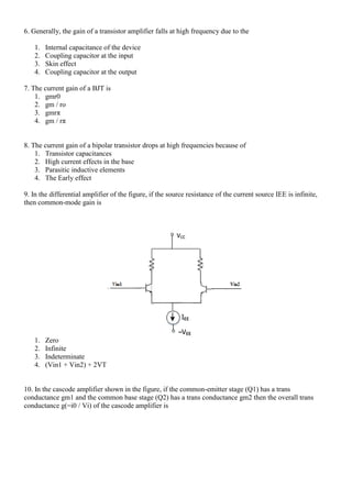
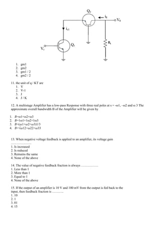

This document contains 30 multiple choice questions about analog and digital electronics concepts like transistors, amplifiers, feedback, and operational characteristics. The questions cover topics such as transistor modeling, amplifier configurations, feedback fraction calculations, effects of feedback on gain and impedance, and applications of common circuits like the emitter follower.