Download to read offline


![Design of a small directive antenna operating at 868 MHz[1]
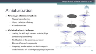
Design of small directive antennas for IoT
3D geometry of 868 MHz small directive antenna
20](https://image.slidesharecdn.com/11815939-230829072448-7d896784/85/11815939-ppt-20-320.jpg)
![Design of a small directive antenna operating at 868 MHz[2]
Design of small directive antennas for IoT
1. Simulation results
2. Total gain (dBi)
3. SWR
4. Reflection
coefficient
1 2
3 4
21](https://image.slidesharecdn.com/11815939-230829072448-7d896784/85/11815939-ppt-21-320.jpg)
![Design of a small directive antenna operating at 868 MHz[3]
Design of small directive antennas for IoT
1. F/B
2. Impedance
3. Radiation pattern
1 3
2
22](https://image.slidesharecdn.com/11815939-230829072448-7d896784/85/11815939-ppt-22-320.jpg)
![Design of a small directive antenna operating at 2400 MHz[1]
Design of small directive antennas for IoT
3D geometry of 2400 MHz small directive antenna
23](https://image.slidesharecdn.com/11815939-230829072448-7d896784/85/11815939-ppt-23-320.jpg)
![Design of a small directive antenna operating at 2400 MHz[2]
Design of small directive antennas for IoT
1. Simulation results
2. Total gain (dBi)
3. SWR
4. Reflection coefficient
1 2
3 4
24](https://image.slidesharecdn.com/11815939-230829072448-7d896784/85/11815939-ppt-24-320.jpg)
![Design of a small directive antenna operating at 2400 MHz[3]
Design of small directive antennas for IoT
1. F/B
2. Impedance
3. Radiation pattern
1 3
2
25](https://image.slidesharecdn.com/11815939-230829072448-7d896784/85/11815939-ppt-25-320.jpg)


This document describes the design of small directive antennas for Internet of Things (IoT) applications. It outlines the introduction to IoT and wireless sensor networks (WSN), discusses antenna theory including common parameters and array designs, and presents the practical work done to design directive antennas operating at 868MHz and 2400MHz. Miniaturization techniques were used to reduce the antenna size. The results showed the designed antennas met requirements for gain, front-to-back ratio, and matching while providing knowledge in IoT, WSN, antenna fundamentals, and design optimization software.


