Downloaded 520 times

![NumericalAperture (NA):
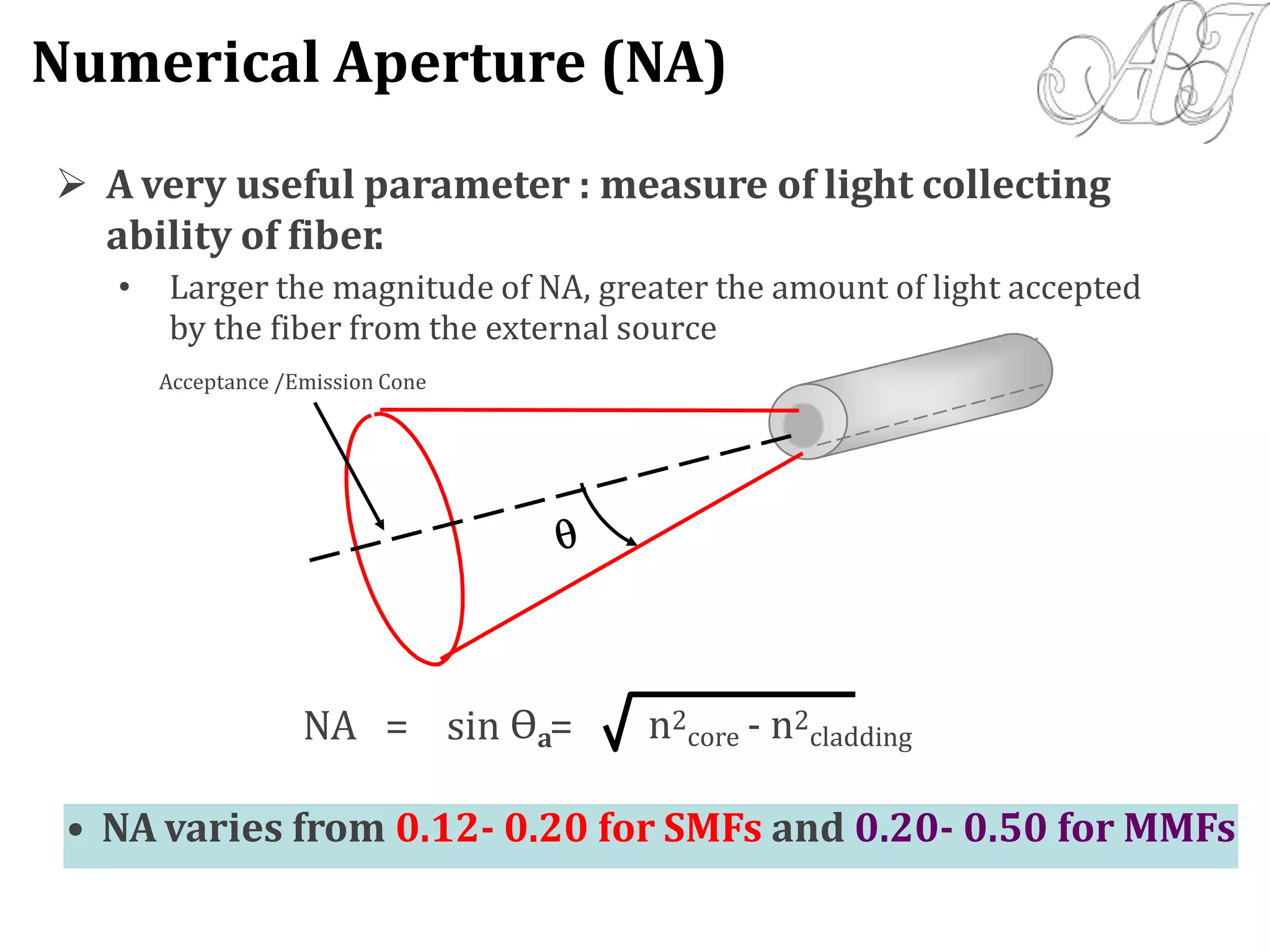
NA = sina = [(n1)2-(n2)2]1/2
0.12-0.20 for SMF, 0.15-0.25 for MMF
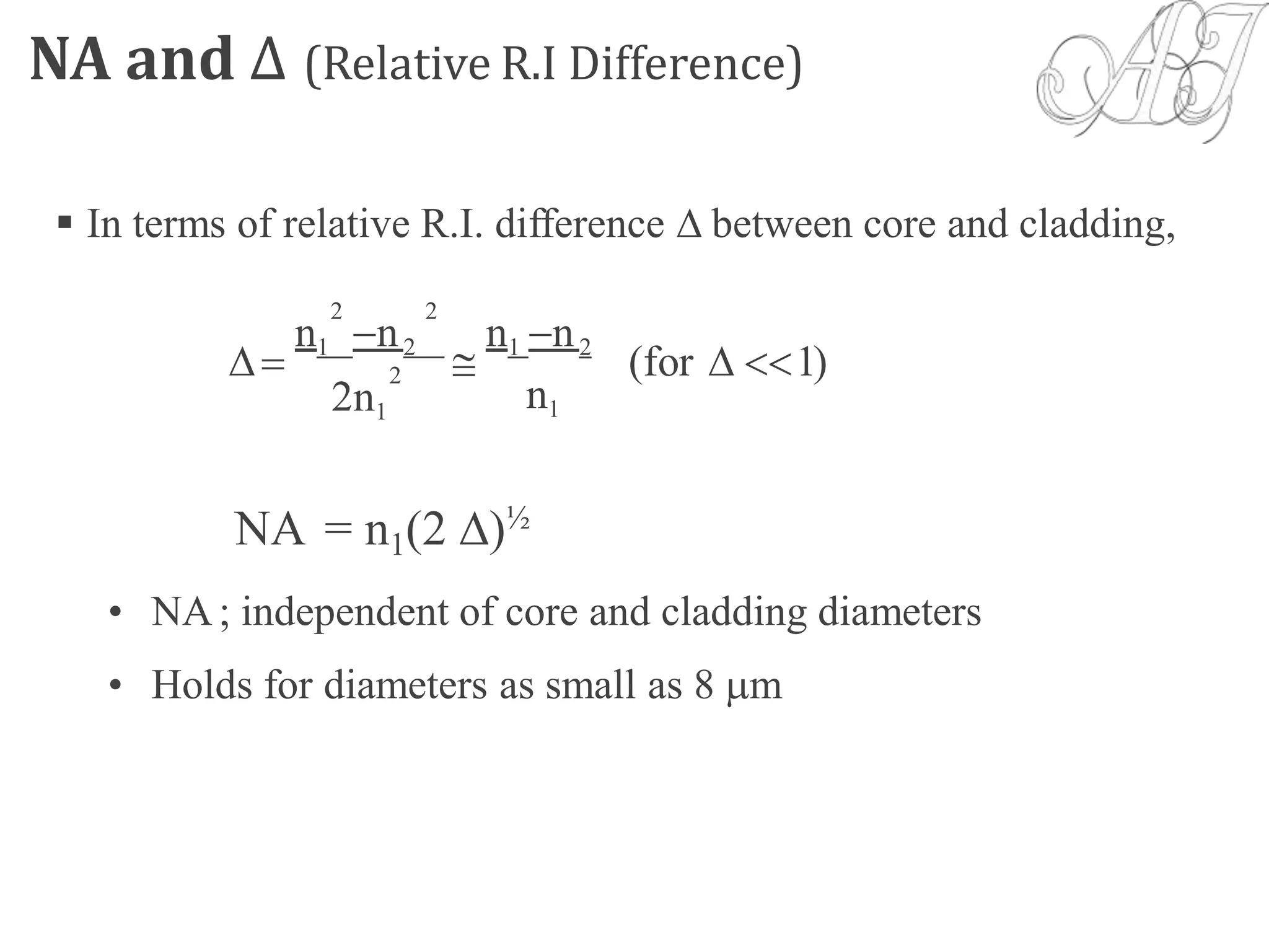
Relative Refractive Index Difference ():
= (n1 –n2)/n ; n- the average refractive index
<0.4% for SMF, >1% for MMF
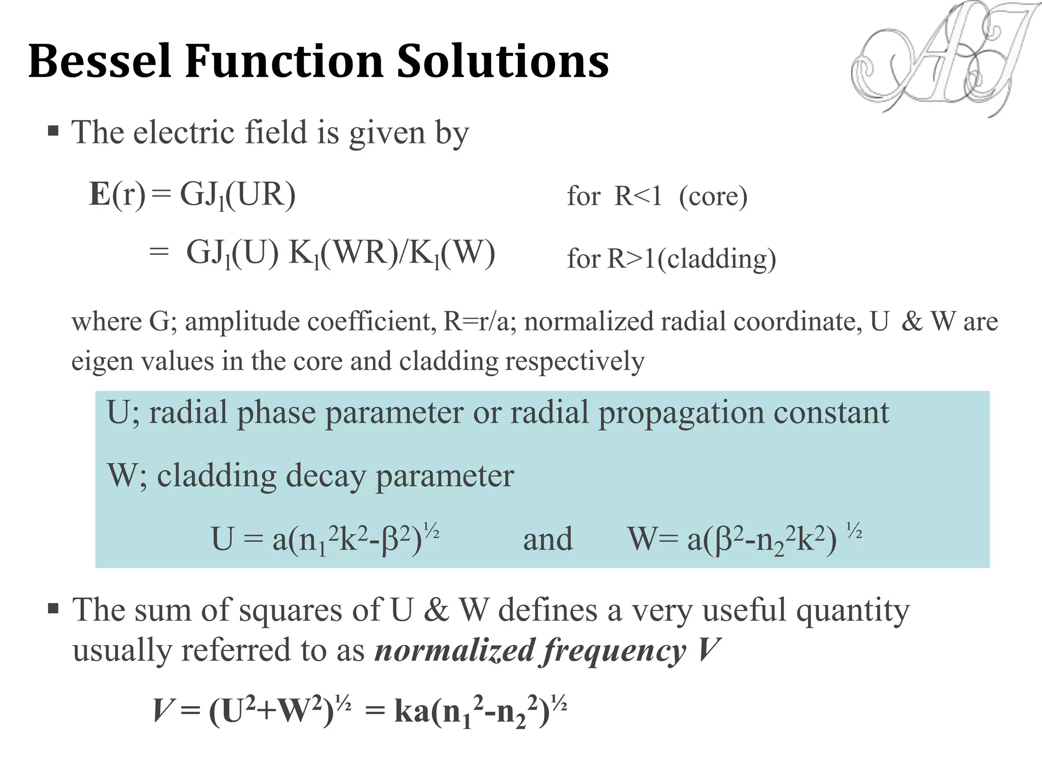
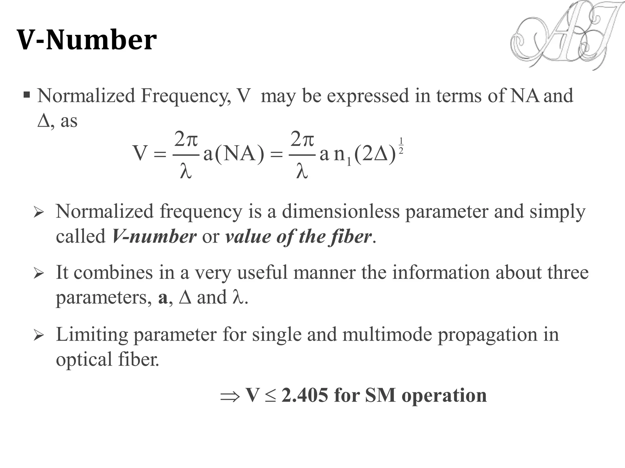
Normalized Frequency or V-Number:
V = [(2a)/] NA
V 2.405 for SMF; 10 for MMF
DESIGNER’S PARAMETERS](https://image.slidesharecdn.com/unit-1-170605053637/75/OPTICAL-FIBER-COMMUNICATION-UNIT-1-45-2048.jpg)


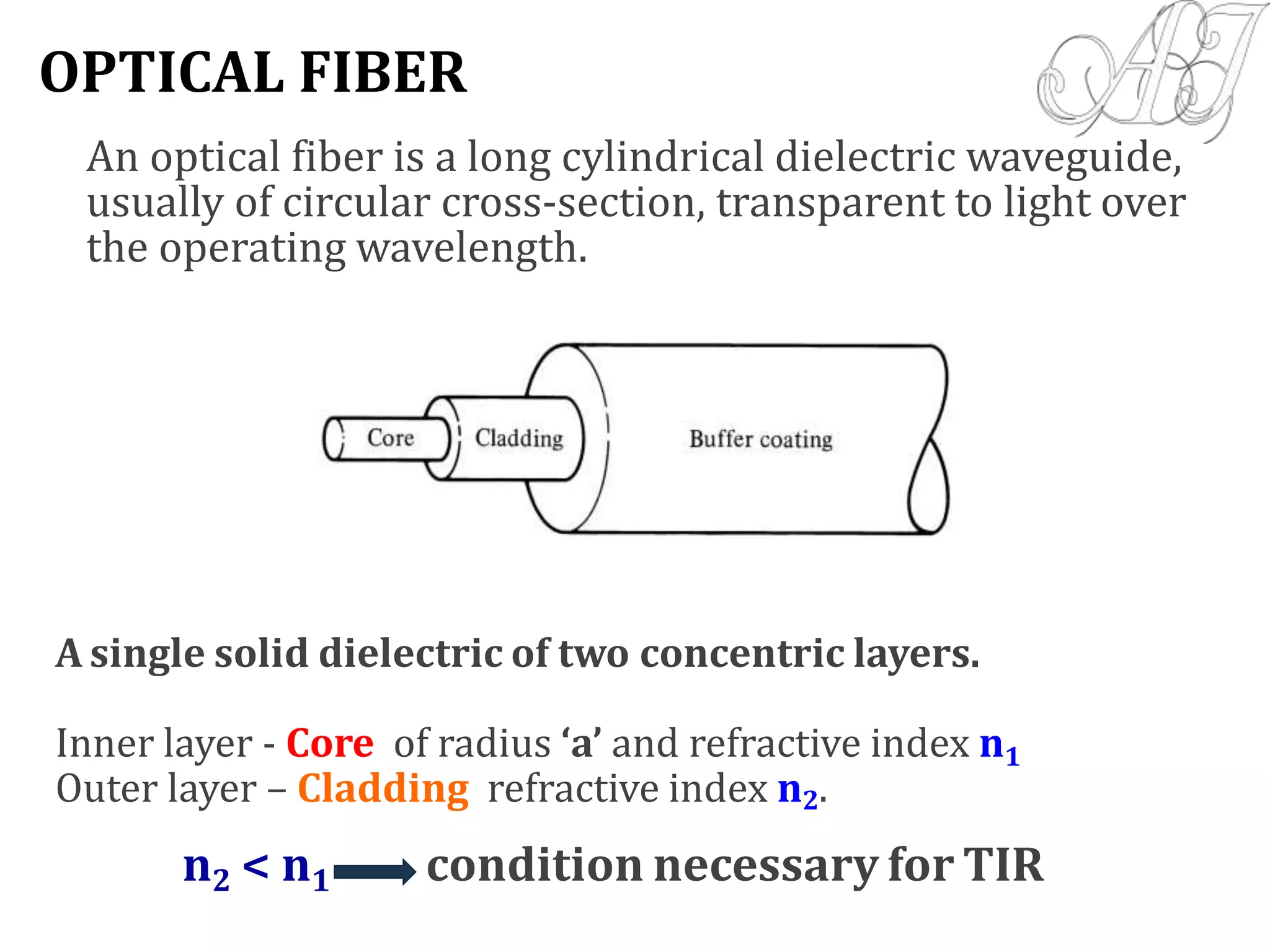
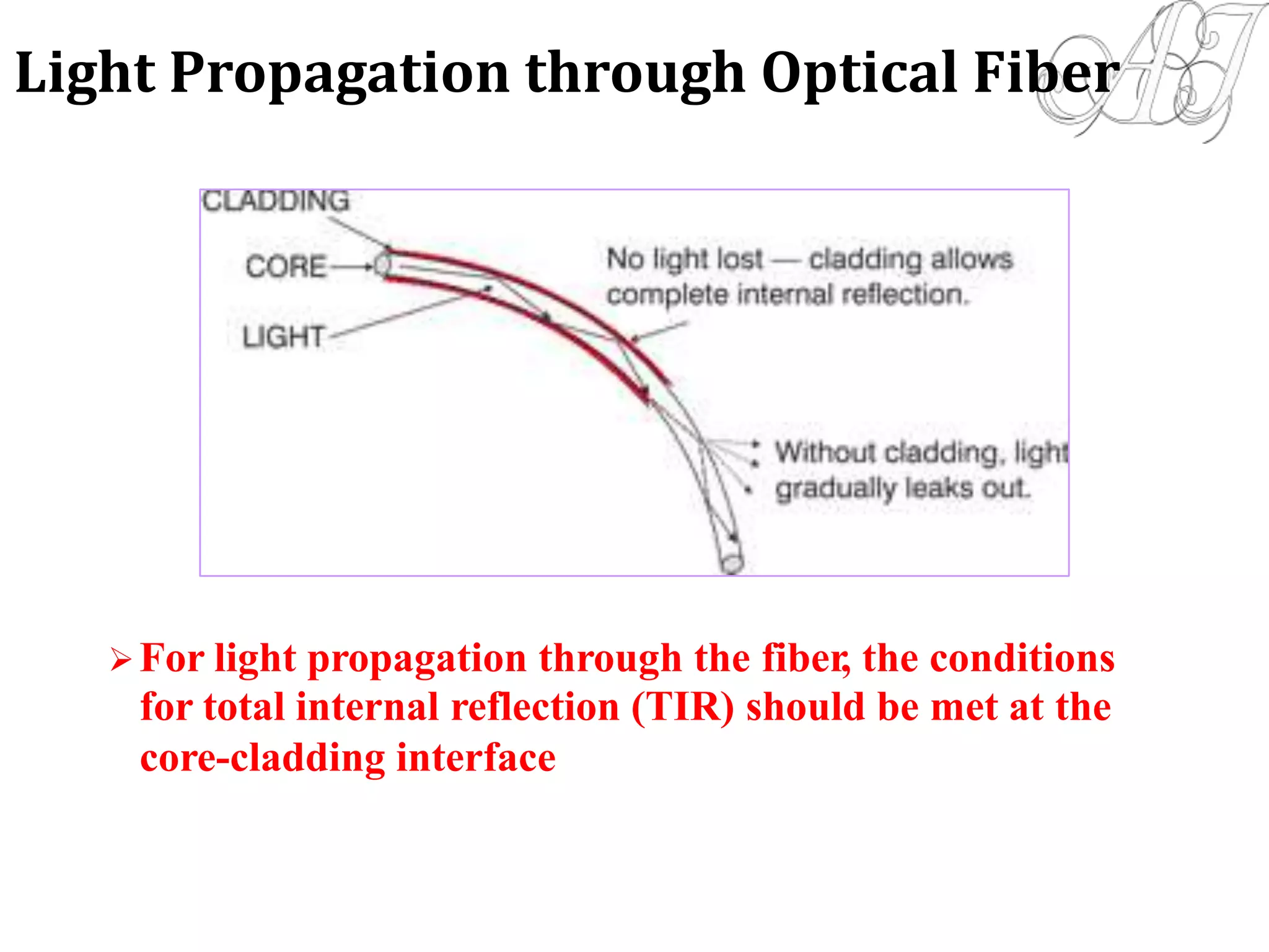
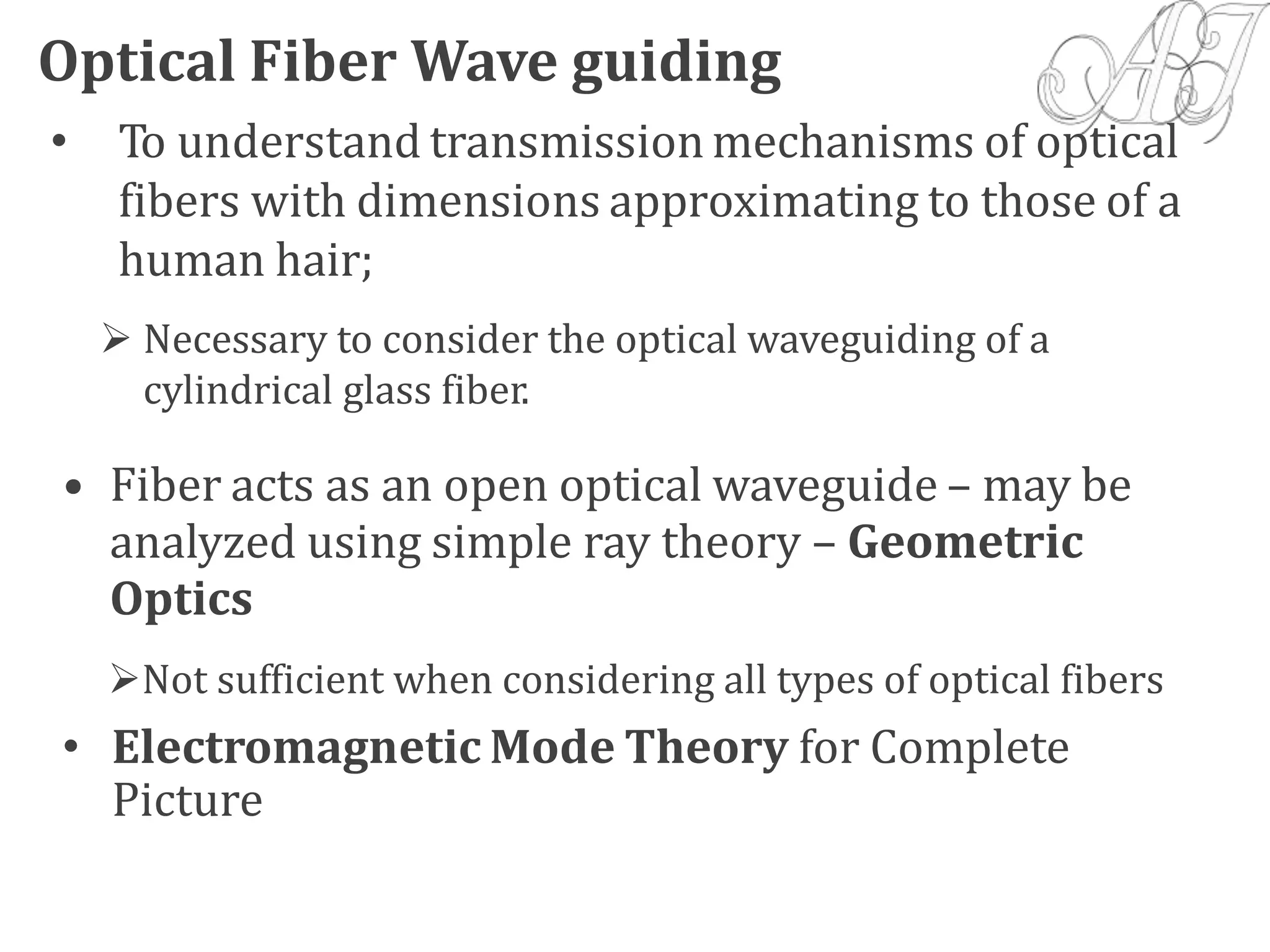
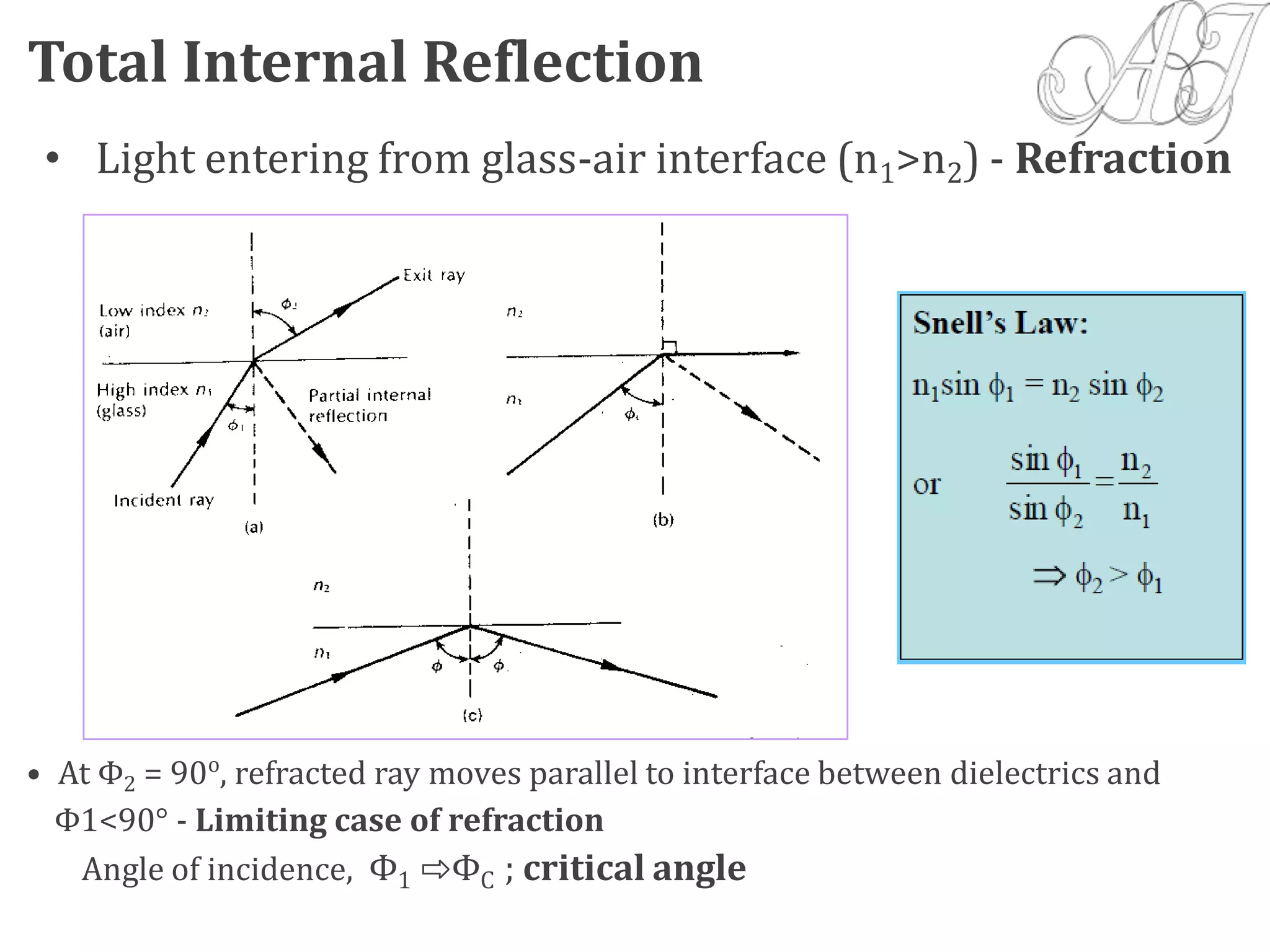
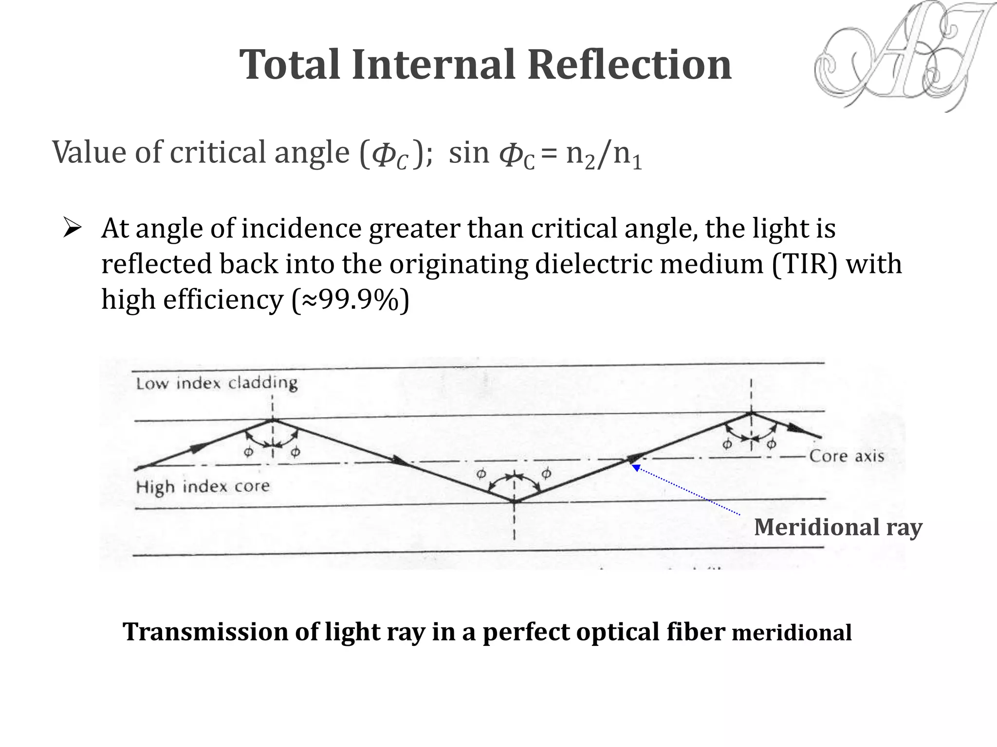
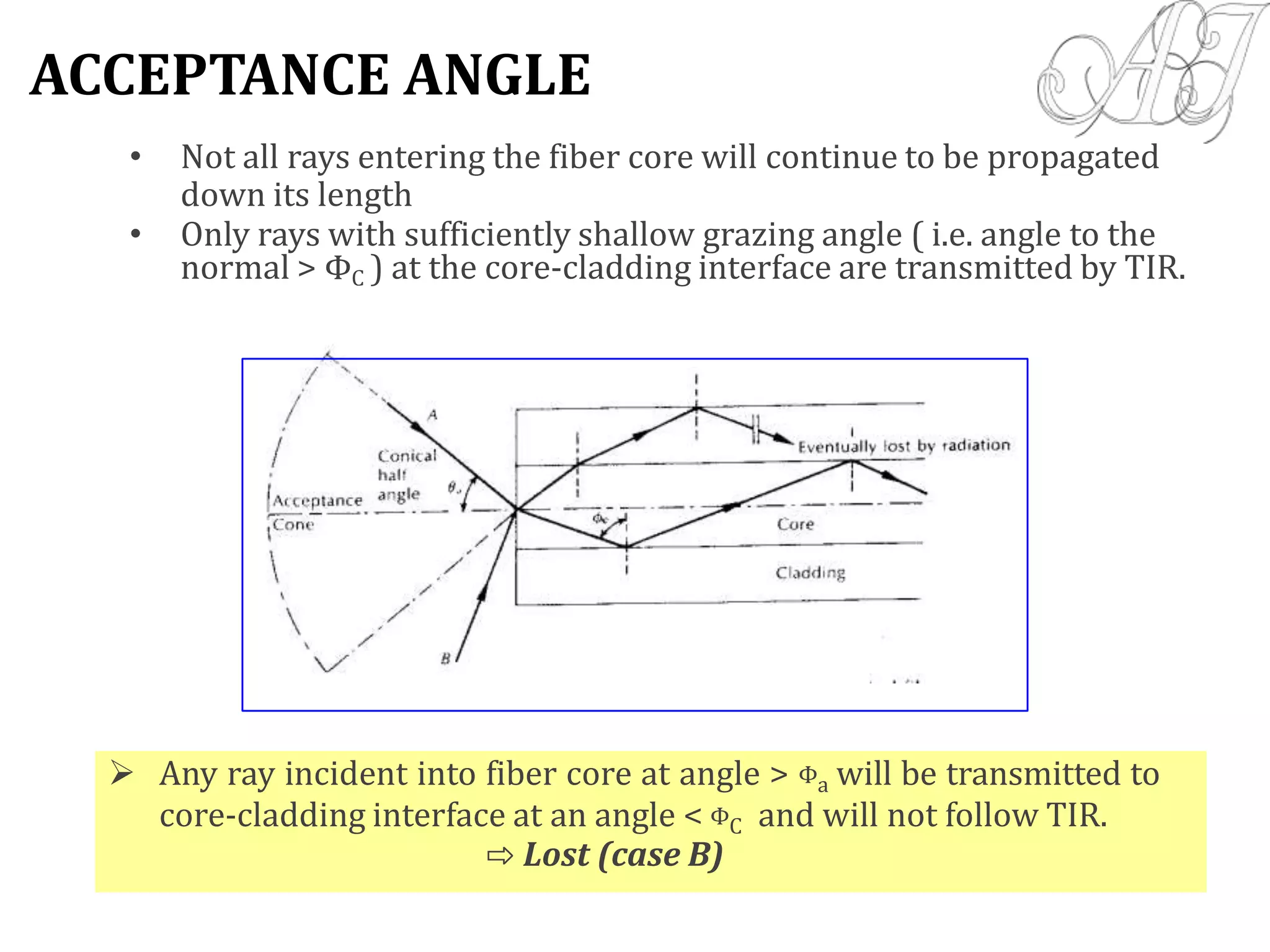
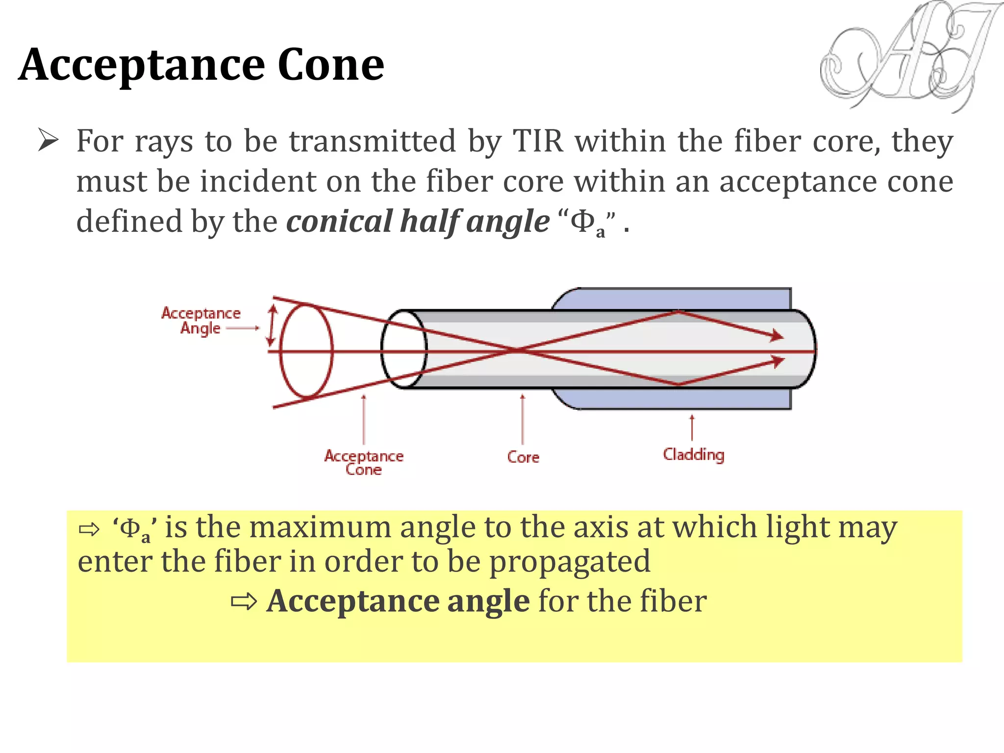
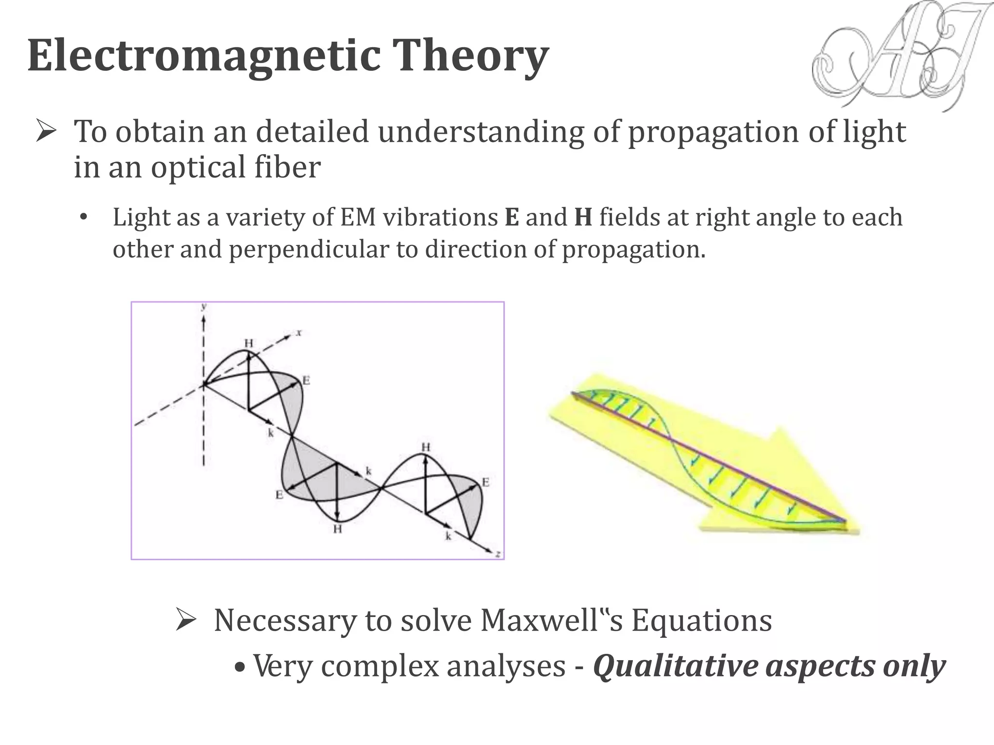
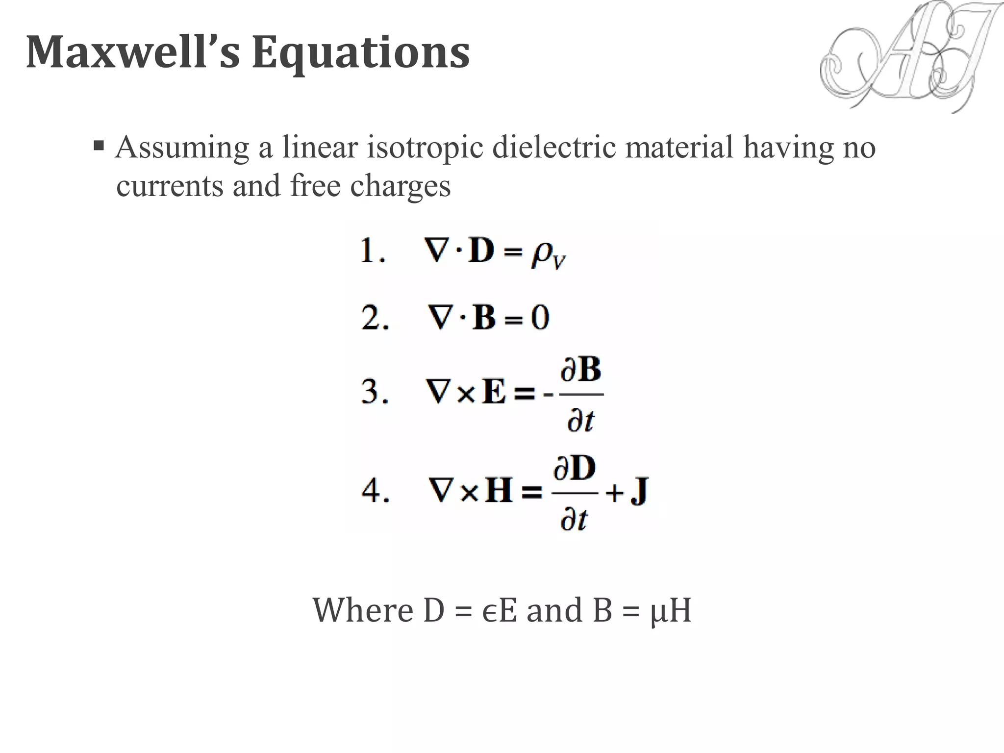
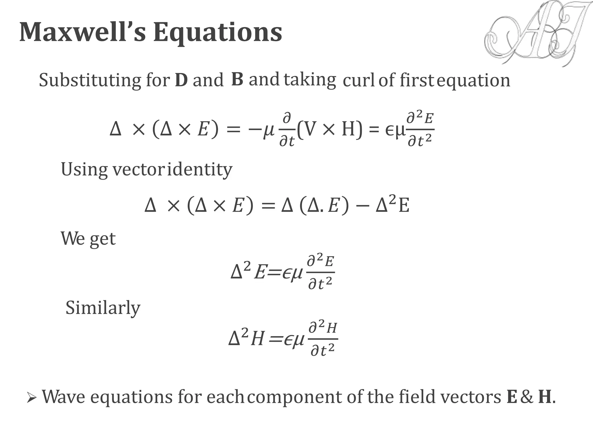
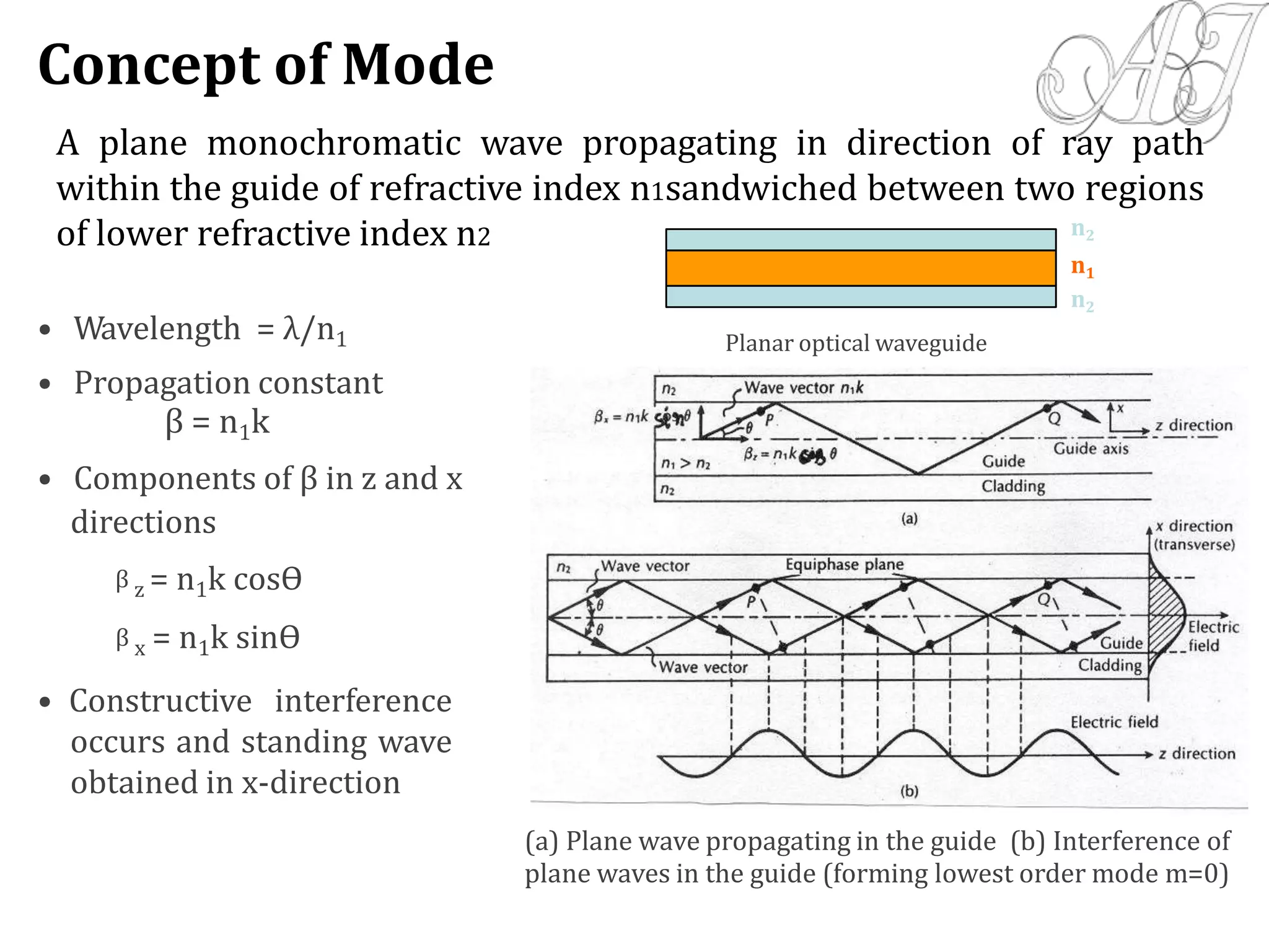
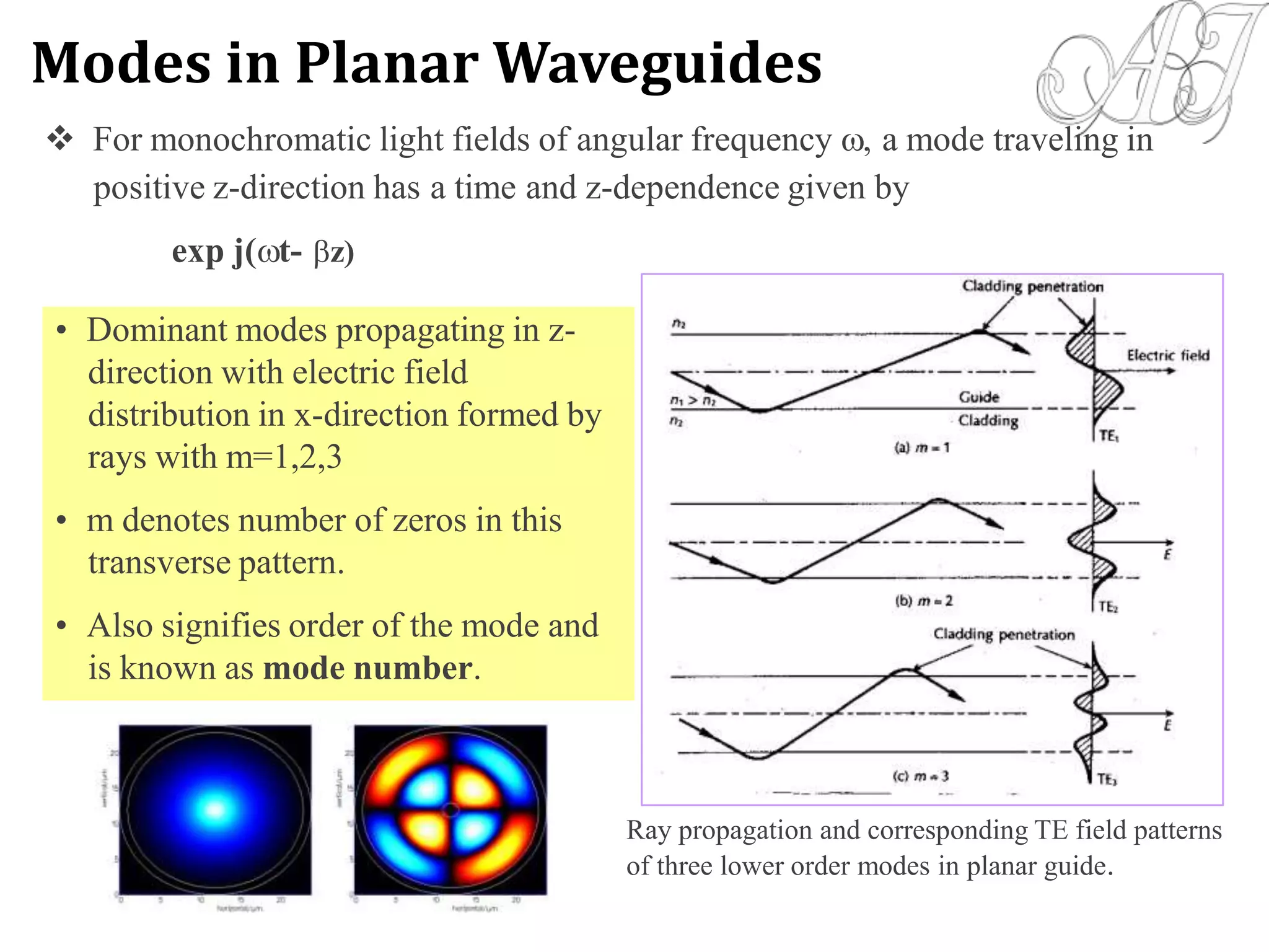
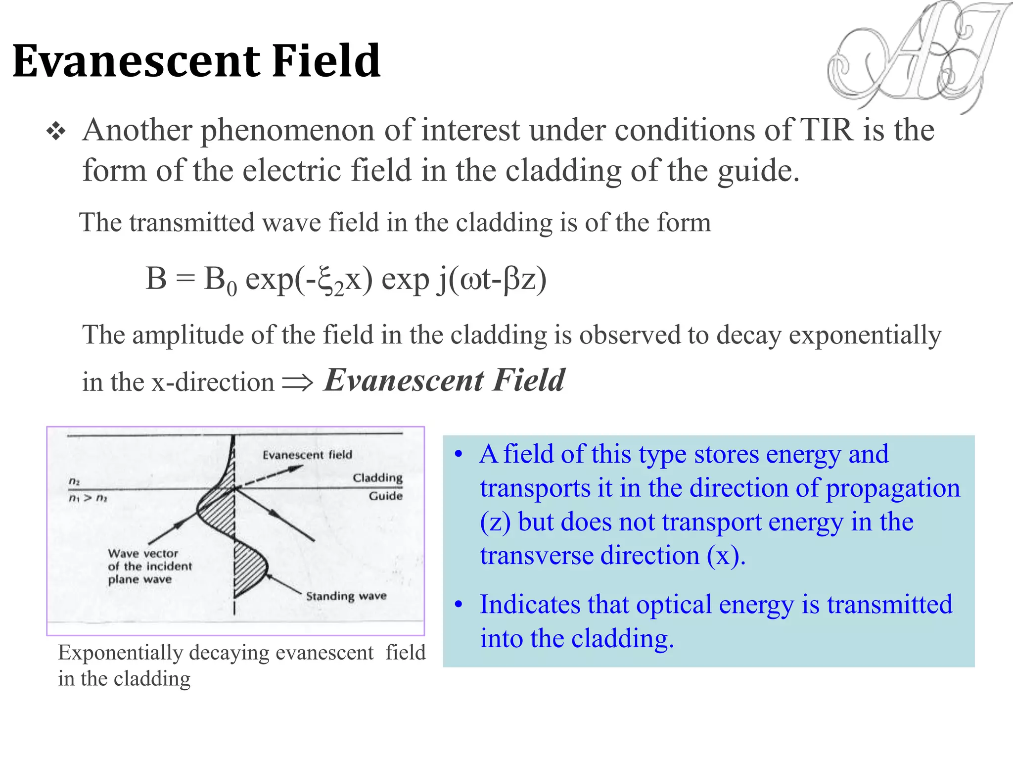
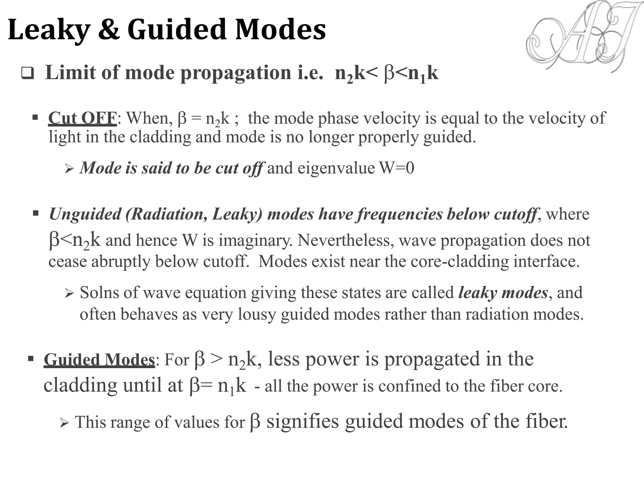
This document provides information about light propagation through optical fibers. It begins by defining an optical fiber as a cylindrical waveguide made of glass that uses total internal reflection to transmit light. It then discusses the fiber's core and cladding layers and the conditions needed for total internal reflection. The key points covered include: - Light propagation is guided through the fiber core by total internal reflection at the core-cladding interface. - Only rays entering the fiber core within the acceptance angle will continue propagating through total internal reflection. - Electromagnetic mode theory is needed to fully understand light propagation in fibers. Discrete modes exist that are solutions to Maxwell's equations. - The evanescent field that penetrates the cl