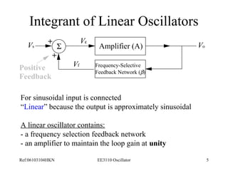
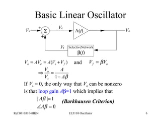
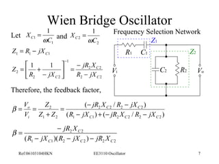
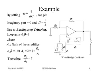
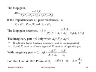
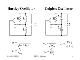
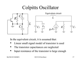
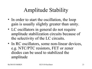
This document discusses oscillators and their various types. It begins with an introduction to oscillators and their characteristics. It then describes different types of linear oscillators, including Wien bridge, RC phase-shift, and LC oscillators. It also discusses oscillator stability and applications such as generating signals for receivers, transmitters, and digital clocks. Specific oscillator circuits like Colpitts and Hartley are analyzed.
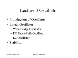

![Applying KVL to the phase-shift network, we have
C C C
V1 Vo
R R R
V = I ( R - jX )
-
I R
C
1 1 2
I R I R jX I R
= - + - -
0 (2 )
C
1 2 3
I R I R jX
= - + -
0 (2 )
2 3
C
I1 I2 I3 Solve for I3, we get
C
R - jX -
R
0
R R jX R
- - -
C
C
R jX R V
1
2 0
C
- -
C
R R jX
R R jX
R
I
- -
- -
-
=
2
0 2
0 0
3
2
I V R
1
( )[(2 )2 2 ] 2 (2 )
Or =
3
R - jX R - jX - R - R R -
jX
C C C Ref:06103104HKN EE3110 Oscillator 11](https://image.slidesharecdn.com/oscillatorsppt-140925123326-phpapp01/85/Oscillatorsppt-11-320.jpg)
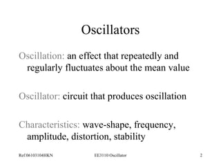
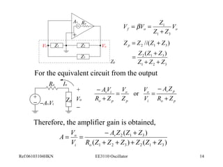
![The output voltage,
3
V = I R =
V R
1
o R jX R jX R R R jX
( )[(2 )2 2 ] 2 (2 )
3
- - - - -
C C C
Hence the transfer function of the phase-shift network is given by,
3
R
( 3 5 2 ) ( 3 6 2 )
V
b = o
=
R RX j X R X
V
- + -
1 C C C
For 180o phase shift, the imaginary part = 0, i.e.,
3 2
X R X XC C C
- = =
6 0 or 0 (Rejected)
2C
R
2 1
RC
Þ =
X 6
6
=
w
and,
b = - 1
29
Note: The –ve sign mean the
phase inversion from the
voltage
Ref:06103104HKN EE3110 Oscillator 12](https://image.slidesharecdn.com/oscillatorsppt-140925123326-phpapp01/85/Oscillatorsppt-12-320.jpg)
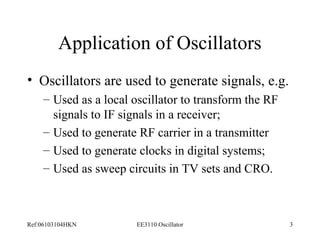
![At node 1,
( ) 1 1 V V i jwL p = +
where,
p i jwC V 1 2 =
2
L
node 1
I1
I2 I3
V1
C2 R C1
Þ V = V (1 -
w LC ) 1 p 2
Apply KCL at node 1, we have
j C V g V V m w w p p
2 + + + j CV =
Vp
0 1 1
1
R
+
-
gmVp
(1 ) 1 0 2 1
+ + - 2
æ + j C
ö çè
j C V g V V LC m w w w p p p
2 R
÷ø
= For Oscillator Vp must not be zero, therefore it enforces,
ö
1 [ ( ) ] 0
gm w w w
= - + + ÷ ÷ø
LC
+ - j C C LC C
1 2
3
1 2
2
2
æ
ç çè
R
R
I4
Ref:06103104HKN EE3110 Oscillator 18](https://image.slidesharecdn.com/oscillatorsppt-140925123326-phpapp01/85/Oscillatorsppt-18-320.jpg)
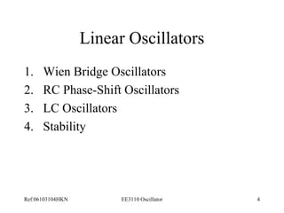
![ö
1 [ ( ) ] 0
gm w w w
= - + + ÷ ÷ø
LC
+ - j C C LC C
1 2
2
2
æ
ç çè
R
R
Imaginary part = 0, we have
1 2
3
w = 1
o LC
T
Real part = 0, yields
g C m =
2
RC
1
C C C T +
1 2
C C
1 2
=
Ref:06103104HKN EE3110 Oscillator 19](https://image.slidesharecdn.com/oscillatorsppt-140925123326-phpapp01/85/Oscillatorsppt-19-320.jpg)


![RF Module Design - [Chapter 7] Voltage-Controlled Oscillator](https://cdn.slidesharecdn.com/ss_thumbnails/rfch7-150613070347-lva1-app6892-thumbnail.jpg?width=640&height=640&fit=bounds)


