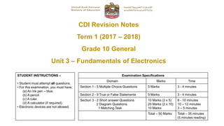
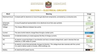
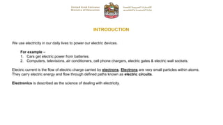
CDI Revision Notes
Term 1 (2017 – 2018)
Grade 10 General
Unit 3 – Fundamentals of Electronics
STUDENT INSTRUCTIONS –
• Student must attempt all questions.
• For this examination, you must have:
(a) An ink pen – blue.
(b) A pencil.
(c) A ruler.
(d) A calculator (if required).
• Electronic devices are not allowed.
Examination Specifications
Domain Marks Time
Section 1 - 5 Multiple Choice Questions 5 Marks 3 - 4 minutes
Section 2 - 5 True or False Statements 5 Marks 3 - 4 minutes
Section 3 - 2 Short answer Questions
2 Diagram Questions
1 Matching Task
10 Marks (2 x 5)
20 Marks (2 x 10)
10 Marks
8 - 10 minutes
10 – 12 minutes
3 – 5 minutes
Total – 50 Marks Total – 35 minutes
(5 minutes reading)
SECTION 1 – ELECTRICAL CIRCUITS
Word Meaning Image
Electrical Circuit A closed path for electrons to move through electrical components, connected by a conductive wire.
Schematic
Diagram
A visual & graphical representation of an electrical circuit that uses symbols.
Voltage The charge difference between two points.
Current The rate at which electric charge flows through a certain point.
Resistance A materials tendency to resist (oppose) the flow of charge (current).
DC An electric current that flows in one direction and has a constant voltage level; used in devices that use
batteries or USB cables for power.
AC An electric current that periodically changes its direction. The voltage level also reverses with the current.
It is used to deliver power to houses, office buildings, etc.
Battery An electrical DC power source.
INTRODUCTION
We use electricity in our daily lives to power our electric devices.
For example –
1. Cars get electric power from batteries.
2. Computers, televisions, air conditioners, cell phone chargers, electric gates & electric wall sockets.
Electric current is the flow of electric charge carried by electrons. Electrons are very small particles within atoms.
They carry electric energy and flow through defined paths known as electric circuits.
Electronics is described as the science of dealing with electricity.
SIGNAL
For receiving and sending information
• Analog Signals
These signals have an infinite number of
values.
Stored in continuous form between minimum
and maximum value.
Examples
• Brightness of sun
• Room temperature
• Speaker
• Mixing colors
• Old radio
• Old photograph
• Digital Signals
These signals have a finite set of possible values.
(0V or 5V)
Stored in coded form (0,1) (min., max. )
Examples
• Light switches in a class room
• Power button of phone
• Game controller buttons
• Calculator screen
• Digital camera
• Digital music player
Electric Circuit : Group of
electrical components
connected by conductors for
current flow.
Voltage
Source
Conductive
Path
Load
It causes the
current to flow
through a circuit.
Consumes electric
power.
Through which
current flows.
Types of Voltage Source
Alternating Current :
Wall Socket
Direct Current :
Battery
ELECTRICAL SCHEMATIC
Ohm’s Law
• Voltage is the difference in
charge between two points.
• Measured in Volts (V).
• Resistance is a
material’s tendency to
resist the flow of
charge (current).
• Measured in Ohms (Ω).
• Current is the rate at which
charge is flowing.
• Measured in Amperes (A).
Problem 1:
Using Ohm’s Law, what is the voltage
difference between point A and B if the
current flowing through the resistor is 15
mA, and the resistance is 100 Ω?
Solution:
V = I × R = 0.015 A × 100 Ω =1.5 V
Problem 2:
If the resistor in the previous example is
replaced with another resistor, that has
double the resistance, how much current
would be flowing in the circuit using the
same 1.5V battery as a voltage supply?
Solution:
V = 1.5 V,
R = 2 × 100Ω = 200 Ω
V = I × R ⟶ I = V / R = 1.5 V / 200 Ω =
0.0075 A = 7.5 mA
Problem 3:
Compare the value of the new current
with the value of the initial current. Justify
your answer.
Solution:
The new current is half the initial current
(7.5 is half of 15). When the resistance
was doubled, the current flowing became
less (half the original current). This is
because current is INVERSELY
proportional to the resistance.
BATTERIES • A battery is a common DC power supply.
• A battery is made up of two plates. One plate is positively charged (+), the other plate is negatively charged (-).
• The plates are surrounded by a chemical solution called electrolyte.
• The electrical energy of a battery is made by converting the chemical energy of the battery. This happens when
a chemical reaction between the plates and the electrolyte produces a voltage difference between the two
plates.
• This makes the electrons flow and generates an electric current.
• The figure below shows some commonly used batteries that are available at the market. Each type has a
different voltage.
• Electric current flows in ONE defined path in series circuits.
• The current must flow through the wires, all the way through
both light bulbs and back to the battery.
SERIES CIRCUITS PARALLEL CIRCUITS
• In parallel circuits, electric current has more than
one path.
• The components are connected to the same
common points, this allows the current to be
distributed over the paths.
SECTION 2 – RESISTORS
Word Meaning Image
Resistor An electronic component
that resists the flow of
current in an electric circuit.
Colour Code
Table
A table used to find out the
resistance value of the
colour coded resistor.
• Resistors are also used to divide voltages.
• The schematic symbol is shown below –
Types of Resistors
Tolerance is the maximum electrical or mechanical variations plus or minus in
the specifications tolerated without affecting the operations of the device.
The resistance of a resistor
For the 4-band resistor, the tolerance is ±5%. This means that the real resistance
of this resistor will not be exactly 1000 Ω. It might be +5% more or -5% less than
1000 Ω. So how much is 5% of 1000 Ω?
Tolerance = ±5 % of 1000 Ω
5% of 1000 Ω =
5
100
×1000 Ω= 50 Ω
∴ Tolerance= ± (5 % of 1000) = ±50 Ω
∴ R=1000 Ω ± 50 Ω
∴R is between (1000-50) Ω and (1000+50) Ω
∴ R is between (950) Ω and (1050) Ω
We call this a ‘range’. So, the range of the resistance is {950 Ω to 1050 Ω}.
For the 5-band resistor, the tolerance is ±1%. This means that the real
resistance of this resistor will not be exactly 57 Ω. It might be +1% more or
-1% less than 57 Ω. So how much is 1% of 57 Ω?
Tolerance = ±1 % of 57 Ω
1% of 57 Ω =
1
100
× 57 Ω= 0.57 Ω
∴ Tolerance= ± (1 % of 57) = ±0.57 Ω
∴ R= 57 Ω ± 0.57 Ω
∴R is between (57 – 0.57) Ω and (57 – 0.57) Ω
∴ R is between (56.43) Ω and (57.57) Ω
We call this a ‘range’. So, the range of the resistance is {56.43 Ω to
56.43 Ω}.
SECTION 3 – ELECTRONIC CALCULATIONS
Word Meaning Image
Breadboard An electronic base
used for building
prototypes for electric
circuits.
Multimeter An electronic device
used for measuring
different electrical
values.
Breadboard Multimeter
• There are three main components –
(a) Nodes – electronic components are
connected to the nodes.
(b) Power Rails – It is used to supply the
board with power. Internally these
nodes are connected vertically.
(c) Terminal stripes – These are the
horizontally connected nodes.
• They are marked with letters (columns)
and numbers (rows) to help build the
circuit properly.
• It also checks the continuity in a
circuit.
• The different values measured are
- current (Amps – AC & DC)
- resistance (Ohms),
- voltage (Volts – AC or DC)
- diode testing
- capacitance (Farads)
- transistor testing, etc.
• It has two probes.
SECTION 4 – EMBEDDED SYSTEMS
Word Meaning
Embedded system A computer system that has a specific function within a larger system.
Microcontroller A minicomputer that fits on a single chip and controls a system.
Processing A series of actions / steps that lead to a certain result.
Input The information or data entered into a system.
Output The information or data produced by a system based on the input information.
• Embedded systems : It is a specialized computer system with a specific function within a
larger mechanical or electrical system. Examples include an air conditioner in car; a
seatbelt warning in a car, a garden watering system & a motion sensitive security system.
• An “embedded system” is known as an input. It is a device that contains a computer unit
or a microcontroller that reads the changes in an environment. It then controls an
output system to change the environment.
• Controller : It is an electronic chip that works as a computer to manage the operation of
electronic devices. It controls certain machines. It can be programmed to read input and
controlling output. It has 3 main parts.

Cdi t1 10_gen_unit3_revision_notes_eot

  • 1.
    CDI Revision Notes Term1 (2017 – 2018) Grade 10 General Unit 3 – Fundamentals of Electronics STUDENT INSTRUCTIONS – • Student must attempt all questions. • For this examination, you must have: (a) An ink pen – blue. (b) A pencil. (c) A ruler. (d) A calculator (if required). • Electronic devices are not allowed. Examination Specifications Domain Marks Time Section 1 - 5 Multiple Choice Questions 5 Marks 3 - 4 minutes Section 2 - 5 True or False Statements 5 Marks 3 - 4 minutes Section 3 - 2 Short answer Questions 2 Diagram Questions 1 Matching Task 10 Marks (2 x 5) 20 Marks (2 x 10) 10 Marks 8 - 10 minutes 10 – 12 minutes 3 – 5 minutes Total – 50 Marks Total – 35 minutes (5 minutes reading)
  • 2.
    SECTION 1 –ELECTRICAL CIRCUITS Word Meaning Image Electrical Circuit A closed path for electrons to move through electrical components, connected by a conductive wire. Schematic Diagram A visual & graphical representation of an electrical circuit that uses symbols. Voltage The charge difference between two points. Current The rate at which electric charge flows through a certain point. Resistance A materials tendency to resist (oppose) the flow of charge (current). DC An electric current that flows in one direction and has a constant voltage level; used in devices that use batteries or USB cables for power. AC An electric current that periodically changes its direction. The voltage level also reverses with the current. It is used to deliver power to houses, office buildings, etc. Battery An electrical DC power source.
  • 3.
    INTRODUCTION We use electricityin our daily lives to power our electric devices. For example – 1. Cars get electric power from batteries. 2. Computers, televisions, air conditioners, cell phone chargers, electric gates & electric wall sockets. Electric current is the flow of electric charge carried by electrons. Electrons are very small particles within atoms. They carry electric energy and flow through defined paths known as electric circuits. Electronics is described as the science of dealing with electricity.
  • 4.
    SIGNAL For receiving andsending information • Analog Signals These signals have an infinite number of values. Stored in continuous form between minimum and maximum value. Examples • Brightness of sun • Room temperature • Speaker • Mixing colors • Old radio • Old photograph • Digital Signals These signals have a finite set of possible values. (0V or 5V) Stored in coded form (0,1) (min., max. ) Examples • Light switches in a class room • Power button of phone • Game controller buttons • Calculator screen • Digital camera • Digital music player
  • 5.
    Electric Circuit :Group of electrical components connected by conductors for current flow. Voltage Source Conductive Path Load It causes the current to flow through a circuit. Consumes electric power. Through which current flows. Types of Voltage Source Alternating Current : Wall Socket Direct Current : Battery
  • 6.
    ELECTRICAL SCHEMATIC Ohm’s Law •Voltage is the difference in charge between two points. • Measured in Volts (V). • Resistance is a material’s tendency to resist the flow of charge (current). • Measured in Ohms (Ω). • Current is the rate at which charge is flowing. • Measured in Amperes (A).
  • 7.
    Problem 1: Using Ohm’sLaw, what is the voltage difference between point A and B if the current flowing through the resistor is 15 mA, and the resistance is 100 Ω? Solution: V = I × R = 0.015 A × 100 Ω =1.5 V Problem 2: If the resistor in the previous example is replaced with another resistor, that has double the resistance, how much current would be flowing in the circuit using the same 1.5V battery as a voltage supply? Solution: V = 1.5 V, R = 2 × 100Ω = 200 Ω V = I × R ⟶ I = V / R = 1.5 V / 200 Ω = 0.0075 A = 7.5 mA Problem 3: Compare the value of the new current with the value of the initial current. Justify your answer. Solution: The new current is half the initial current (7.5 is half of 15). When the resistance was doubled, the current flowing became less (half the original current). This is because current is INVERSELY proportional to the resistance. BATTERIES • A battery is a common DC power supply. • A battery is made up of two plates. One plate is positively charged (+), the other plate is negatively charged (-). • The plates are surrounded by a chemical solution called electrolyte. • The electrical energy of a battery is made by converting the chemical energy of the battery. This happens when a chemical reaction between the plates and the electrolyte produces a voltage difference between the two plates. • This makes the electrons flow and generates an electric current. • The figure below shows some commonly used batteries that are available at the market. Each type has a different voltage.
  • 8.
    • Electric currentflows in ONE defined path in series circuits. • The current must flow through the wires, all the way through both light bulbs and back to the battery. SERIES CIRCUITS PARALLEL CIRCUITS • In parallel circuits, electric current has more than one path. • The components are connected to the same common points, this allows the current to be distributed over the paths.
  • 9.
    SECTION 2 –RESISTORS Word Meaning Image Resistor An electronic component that resists the flow of current in an electric circuit. Colour Code Table A table used to find out the resistance value of the colour coded resistor. • Resistors are also used to divide voltages. • The schematic symbol is shown below – Types of Resistors Tolerance is the maximum electrical or mechanical variations plus or minus in the specifications tolerated without affecting the operations of the device.
  • 10.
    The resistance ofa resistor For the 4-band resistor, the tolerance is ±5%. This means that the real resistance of this resistor will not be exactly 1000 Ω. It might be +5% more or -5% less than 1000 Ω. So how much is 5% of 1000 Ω? Tolerance = ±5 % of 1000 Ω 5% of 1000 Ω = 5 100 ×1000 Ω= 50 Ω ∴ Tolerance= ± (5 % of 1000) = ±50 Ω ∴ R=1000 Ω ± 50 Ω ∴R is between (1000-50) Ω and (1000+50) Ω ∴ R is between (950) Ω and (1050) Ω We call this a ‘range’. So, the range of the resistance is {950 Ω to 1050 Ω}. For the 5-band resistor, the tolerance is ±1%. This means that the real resistance of this resistor will not be exactly 57 Ω. It might be +1% more or -1% less than 57 Ω. So how much is 1% of 57 Ω? Tolerance = ±1 % of 57 Ω 1% of 57 Ω = 1 100 × 57 Ω= 0.57 Ω ∴ Tolerance= ± (1 % of 57) = ±0.57 Ω ∴ R= 57 Ω ± 0.57 Ω ∴R is between (57 – 0.57) Ω and (57 – 0.57) Ω ∴ R is between (56.43) Ω and (57.57) Ω We call this a ‘range’. So, the range of the resistance is {56.43 Ω to 56.43 Ω}.
  • 11.
    SECTION 3 –ELECTRONIC CALCULATIONS Word Meaning Image Breadboard An electronic base used for building prototypes for electric circuits. Multimeter An electronic device used for measuring different electrical values. Breadboard Multimeter • There are three main components – (a) Nodes – electronic components are connected to the nodes. (b) Power Rails – It is used to supply the board with power. Internally these nodes are connected vertically. (c) Terminal stripes – These are the horizontally connected nodes. • They are marked with letters (columns) and numbers (rows) to help build the circuit properly. • It also checks the continuity in a circuit. • The different values measured are - current (Amps – AC & DC) - resistance (Ohms), - voltage (Volts – AC or DC) - diode testing - capacitance (Farads) - transistor testing, etc. • It has two probes. SECTION 4 – EMBEDDED SYSTEMS Word Meaning Embedded system A computer system that has a specific function within a larger system. Microcontroller A minicomputer that fits on a single chip and controls a system. Processing A series of actions / steps that lead to a certain result. Input The information or data entered into a system. Output The information or data produced by a system based on the input information.
  • 12.
    • Embedded systems: It is a specialized computer system with a specific function within a larger mechanical or electrical system. Examples include an air conditioner in car; a seatbelt warning in a car, a garden watering system & a motion sensitive security system. • An “embedded system” is known as an input. It is a device that contains a computer unit or a microcontroller that reads the changes in an environment. It then controls an output system to change the environment. • Controller : It is an electronic chip that works as a computer to manage the operation of electronic devices. It controls certain machines. It can be programmed to read input and controlling output. It has 3 main parts.