Feedback Amplifiers
Feedback Concepts:
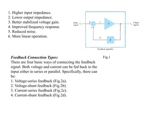
Atypical feedback connection is shown in Fig.1. The input signal ,VS ,is applied to a mixer
network, where it is combined with a feedback signal, Vf. The difference of these signals,
Vi, is then the input voltage to the amplifier. A portion of the amplifier output (sampled
signal), Vo, is connected to the feedback network (β), which provides a reduced portion of
the output as feedback signal to the input mixer network.
There are two basic types of feedback in amplifiers positive feedback and negative
feedback. When the feedback energy (voltage or current) is in phase with the input signal
and thus aids it, it is called positive feedback. Both amplifier and feedback network
introduce a phase shift of 180°. The result is a 360° phase shift around the loop, When the
feedback energy (voltage or current) is out of phase with the input signal and thus opposes
it, it is called negative feedback the amplifier introduces a phase shift of 180° into the
circuit while the feedback network is so designed that it introduces no phase shift if the
feedback signal is of opposite polarity to the input signal, as shown in Fig.1, negative
feedback results. While negative feedback results in reduced overall voltage gain, a number
of improvements are obtained, among them being:
2.
1. Higher inputimpedance.
2. Lower output impedance.
3. Better stabilized voltage gain.
4. Improved frequency response.
5. Reduced noise.
6. More linear operation.
Fig.1
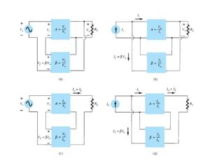
Feedback Connection Types:
There are four basic ways of connecting the feedback
signal. Both voltage and current can be fed back to the
input either in series or parallel. Specifically, there can
be:
1. Voltage-series feedback (Fig.2a).
2. Voltage-shunt feedback (Fig.2b).
3. Current-series feedback (Fig.2c).
4. Current-shunt feedback (Fig.2d).
4.
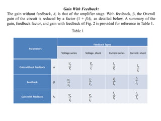
Gain With Feedback:
Thegain without feedback, A, is that of the amplifier stage. With feedback, β, the Overall
gain of the circuit is reduced by a factor (1 + βA), as detailed below. A summary of the
gain, feedback factor, and gain with feedback of Fig. 2 is provided for reference in Table 1.
Table 1
Parameters
Feedback Types
Voltage-series Voltage- shunt Current-series Current- shunt
Gain without feedback A
Feedback β
Gain with feedback Af
5.
Voltage-Series Feedback:
From Fig.2a and Table 1;
The gain with feedback is:
Voltage-Shunt Feedback:
From Fig. 2b and Table 1;
The gain with feedback is:
6.
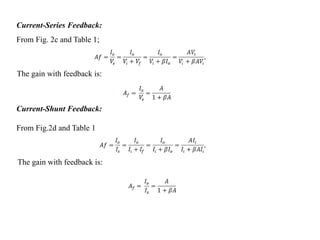
Current-Series Feedback:
From Fig.2c and Table 1;
The gain with feedback is:
Current-Shunt Feedback:
From Fig.2d and Table 1
The gain with feedback is:
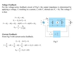
Voltage Feedback:
For thevoltage-series feedback circuit of Fig.3, the output impedance is determined by
applying a voltage, V, resulting in a current, I, with Vs shorted out (Vs = 0). The voltage V
is then
Current Feedback:
From Fig.5 with current-series feedback;
Fig.5
10.
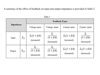
A summary ofthe effect of feedback on input and output impedance is provided in Table 2
11.
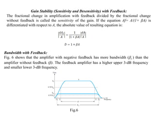
Gain Stability (Sensitivityand Desensitivity) with Feedback:
The fractional change in amplification with feedback divided by the fractional change
without feedback is called the sensitivity of the gain. If the equation Af= A/(1+ βA) is
differentiated with respect to A, the absolute value of resulting equation is:
Bandwidth with Feedback:
Fig. 6 shows that the amplifier with negative feedback has more bandwidth (βf ) than the
amplifier without feedback (β). The feedback amplifier has a higher upper 3-dB frequency
and smaller lower 3-dB frequency.
Fig.6
12.
Method of Analysisof a Feedback Amplifier:
To find the input circuit:
1. Set Vo = 0 for voltage feedback (sampling). In other words, short the output node.
2. Set Io = 0 for current feedback (sampling). In other words, open the output loop.
To find the output circuit:
1. Set Vi = 0 for shunt feedback. In other words, short the input node.
2. Set Ii = 0 for series feedback. In other words, open the input loop.
Table 3 summarizes the above procedure and should be referred to when
H.W:- Calculate Avf, Zif ,and Zof for the amplifier circuit shown , given : gm = 1mv , rd =
20k
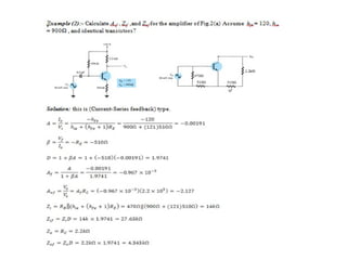
H.W :- Calculate Avf , Zif ,and Zof for the amplifier circuit ,Assume hfe = 50, hie = 1.1kΩ ,
and identical transistors?