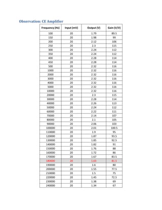
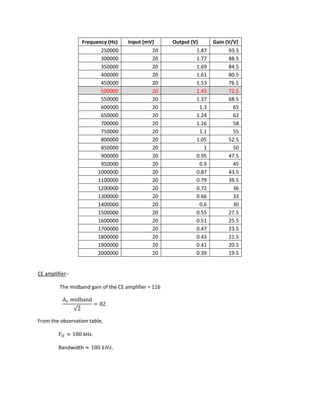
EC 204: ANLOG CIRCUITS LABORATORY
Experiment 4
CE-CB Cascode Amplifier
Sachin Rajoria 08010826
Manzil Zaheer 08010252
Payoj Kissan 08010823
To design CE amplifier and CE-CB case code amplifier and compare their gain and bandwidth.
Objective:
 To make a single stage CE amplifier and experimentally determine its frequency response.
 To modify the CE amplifier into CE-CB case code amplifier and experimentally determine its
frequency response.
 To compare the gain and bandwidth of CE amplifier with that of CE-CB case code amplifier and
justify the result.
Instruments/Materials Required:
1. NPN Transistor: 2N2222A x2
2. Capacitors:
I. 10 µF x3
II. 100 µF x1
3. Resistors:
a. 1 kΩ x5
b. 3.3 kΩ x1
c. 10 kΩ x1
d. 22 kΩ x2
e. 100 kΩ x1
f. 150 kΩ x2
4. Breadboard x1
5. Function generator x1
6. DC Power Supply: 15V x1
Theory:
Bandwidth=𝐹𝐹𝐻𝐻 − 𝐹𝐹𝐿𝐿
If 𝐹𝐹𝐻𝐻 ≫ 𝐹𝐹𝐿𝐿 , then
∴ Bandwidth≈ 𝐹𝐹𝐻𝐻
The capacitors in the circuit determine the frequency response i.e. lower and higher cut-off frequencies.
General expression of gain
As =
𝑎𝑎 𝑚𝑚 (𝑠𝑠 + 𝑤𝑤𝑧𝑧1)(𝑠𝑠 + 𝑤𝑤𝑧𝑧2) … … … … … … . (𝑠𝑠 + 𝑤𝑤𝑧𝑧𝑧𝑧 )
�𝑠𝑠 + 𝑤𝑤𝑝𝑝1��𝑠𝑠 + 𝑤𝑤𝑝𝑝2� … … … … . �𝑠𝑠 + 𝑤𝑤𝑝𝑝𝑝𝑝 �
Dominant pole approximation
wL ≈ wp1 (two octave or four time higher)
: if wpi ≫ all other poles and zero frequencies,wp1 is the dominant pole
frequency and
In the case of no dominant pole wL = �(𝑤𝑤𝑝𝑝1
2
+ 𝑤𝑤𝑝𝑝2
2
… − 2𝑤𝑤𝑧𝑧1
2
− 2𝑤𝑤𝑧𝑧2
2
… )
High frequency response
Gain
As =
𝑎𝑎 𝑚𝑚 �1 +
𝑠𝑠
𝑤𝑤 𝑧𝑧1
� �1 +
𝑠𝑠
𝑤𝑤 𝑧𝑧2
� … . . �1 +
𝑠𝑠
𝑤𝑤 𝑧𝑧𝑧𝑧
�
�1 +
𝑠𝑠
𝑤𝑤 𝑝𝑝1
� �1 +
𝑠𝑠
𝑤𝑤 𝑝𝑝2
� … . . �1 +
𝑠𝑠
𝑤𝑤 𝑝𝑝𝑝𝑝
�
:
If wp1 ≪ all other poles and zero frequencies then,
wH ≈ wp1
Else
wH =
1
�
1
wp1
2 +
1
wp2
2 … − 2 �
1
wz1
2 +
1
wz2
2 + ⋯ +
1
wzn
2 �
CE Amplifier
…
Calculation of lower cut-off frequency of CE amplifier
Cut-off frequency of capacitor at input
:
∴ 𝐹𝐹𝐶𝐶 =
1
2𝜋𝜋𝑅𝑅𝑒𝑒𝑒𝑒 𝐶𝐶𝑒𝑒𝑒𝑒
Where: Req = �R6 + R2�|R1|�β(R3)�
= (1k+22k||100k||170 (1k))
=16.30kΩ
Ceq =10µF
∴ 𝐹𝐹𝐶𝐶 = 0.9764𝐻𝐻𝐻𝐻
β
Cut-off frequency of emitter capacitance
∴ 𝐹𝐹𝐶𝐶 =
1
2𝜋𝜋𝑅𝑅𝑒𝑒𝑒𝑒 𝐶𝐶𝑒𝑒𝑒𝑒
Where: Req = R1||R3
R1 = 1kΩ
R3 = re +
𝑅𝑅6�|𝑅𝑅2|�𝑅𝑅1
𝛽𝛽
re =
VT
IE
=
26𝑚𝑚𝑚𝑚
1.87𝑚𝑚𝑚𝑚
= 13.90Ω
Req = 13.70 Ω
∴ 𝐹𝐹𝐶𝐶 = 116.17𝐻𝐻𝐻𝐻
Cut-off frequency of out-put capacitance
∴ 𝐹𝐹𝐶𝐶 =
1
2𝜋𝜋𝑅𝑅𝑒𝑒𝑒𝑒 𝐶𝐶𝑒𝑒𝑒𝑒
Where: Req = 3.3𝑘𝑘 + 10𝑘𝑘
=13.3kΩ
Ceq = 10µF
∴ 𝐹𝐹𝐶𝐶 = 1.19𝐻𝐻𝐻𝐻
∴The lower cut-off frequency of CE amplifier is=116.17Hz
Calculation of higher cut-off frequency of CE amplifier
Let A is the gain of CE amplifier
𝐴𝐴 = �−
𝑅𝑅𝐶𝐶||𝑅𝑅𝐿𝐿
𝑟𝑟𝑒𝑒
�
:
Where:
RL = 10kΩ
RC = 3.3kΩ
re = 13.90Ω
Gain 𝐴𝐴 = 178.50
Ceq = Cin = Cπ + Cμ(1 + A)
From data sheet Cπ = 25pF, Cμ = 8pF
Cin = 1559.89pF
Rin = �rx + RS�|R2|�R3�||βre
= 676.04Ω
Fin,H = 150.922kHz
Fout ,H =
1
2π(Rc||RL)(Cμ �
1
A
+ 1�)
=8.62MHz
∴The higher frequency cut-off of the CE amplifier=150.922kHz
CE-CB case-code amplifier
Calculation of lower cut-off frequency of CE –CB amplifier
Calculation of frequency due to emitter resistance
:
Rnet = R1||R3
= 1k|| �13.90Ω +
�22k�|25k|�1k�
170
�
= 18.953Ω
FCE = 83.98Hz
Calculation of frequency due to out-put resistance
Fc,out =
1
2π(3.3k + 10k)(10μF)
=1.19Hz
Calculation of frequency due to input capacitance
Rnet = R6 + �R7�|R2|�βR3�
=1k+ (22k||25k||130(1k))
=11.73kΩ
FC=1.35Hz
Calculation of frequency due to CB
𝐹𝐹𝐶𝐶𝐶𝐶 =
1
2𝜋𝜋(25𝑘𝑘||75𝑘𝑘)(10𝜇𝜇𝜇𝜇)
=0.849Hz
Theoretical justification
The lower cut-off frequency of both CE and CE-CB case code amplifier are almost equal.
:-
CE amplifier (high frequency)
Because the gain of the CE amplifier is very high, the Miller capacitance transferred to the input side i.e.
Cµ(A + 1) because very large and as the result the higher cut-off frequency which is determined by it
decreases.
FH =
1
2π �Cπ + Cμ(A + 1)� Req
:
Gain A = ()
∴ FH is decreased considerably
The Miller capacitance at the output side does not play a role in determining FH because Cµ �
1
A
+ 1� is
approximately equal to Cμ and therefore the frequency determined by it, is higher compared to that at
the input
∴ The frequency determined by the capacitance at the input side is the dominant frequency and
determines the higher cut-off frequencies.
CE-CB case code amplifiers:-
CE stage:-
The difference between the CE stage of CE-CB case code and CE amplifier is the gain.
The gain of the CE stage in the CE-CB case code is given by this approximation, Gain is =
re2
re1
≈ 1
The Miller capacitance at the input in case of CE-CB case code is much lower than that of CE
amplifier. The frequency due to the Miller capacitance at input in case of CE-CB case code is higher as
compare to the CE amplifier.
𝐹𝐹ℎ1 =
1
2𝜋𝜋(𝐶𝐶𝜋𝜋+ 𝐶𝐶𝜇𝜇 ( ))𝑅𝑅𝑒𝑒𝑒𝑒
>
1
2𝜋𝜋(𝐶𝐶𝜋𝜋+ 𝐶𝐶𝜇𝜇 ( ))𝑅𝑅𝑒𝑒𝑒𝑒
Bandwidth of the CE-CB amplifier is higher than that of CE amplifier.
CB stage:-
The frequency response due to Cπ is much smaller as compared to Cμ.
The frequency response due toCμ,
Fcb =
1
2πCμ(Rc ||RL )
This frequency is comparable to frequency determined by the input side of CE stage in CE-CB case code.
∴ FH =
1
�
1
Fμ
+
1
Fh1
Thus, the net high frequency cut-off calculated is higher than the case of CE amplifier.
Observation: CE Amplifier
Frequency (Hz) Input (mV) Output (V) Gain (V/V)
100 20 1.79 89.5
150 20 1.98 99
200 20 2.12 106
250 20 2.3 115
300 20 2.24 112
350 20 2.24 112
400 20 2.28 114
450 20 2.28 114
500 20 2.32 116
1000 20 2.32 116
2000 20 2.32 116
3000 20 2.32 116
4000 20 2.32 116
5000 20 2.32 116
10000 20 2.32 116
20000 20 2.3 115
30000 20 2.28 114
40000 20 2.26 113
50000 20 2.24 112
60000 20 2.22 111
70000 20 2.14 107
80000 20 2.1 105
90000 20 2.06 103
100000 20 2.01 100.5
110000 20 1.9 95
120000 20 1.87 93.5
130000 20 1.85 92.5
140000 20 1.82 91
150000 20 1.76 88
160000 20 1.72 86
170000 20 1.67 83.5
180000 20 1.63 81.5
190000 20 1.6 80
200000 20 1.55 77.5
210000 20 1.5 75
220000 20 1.45 72.5
230000 20 1.38 69
240000 20 1.34 67
Frequency (Hz) Input (mV) Output (V) Gain (V/V)
250000 20 1.3 65
260000 20 1.27 63.5
270000 20 1.24 62
280000 20 1.22 61
290000 20 1.18 59
300000 20 1.16 58
310000 20 1.13 56.5
320000 20 1.11 55.5
330000 20 1.09 54.5
340000 20 1.06 53
350000 20 1.04 52
360000 20 1.01 50.5
370000 20 1 50
380000 20 0.98 49
390000 20 0.95 47.5
400000 20 0.93 46.5
410000 20 0.92 46
420000 20 0.9 45
430000 20 0.89 44.5
440000 20 0.86 43
450000 20 0.85 42.5
460000 20 0.84 42
470000 20 0.82 41
480000 20 0.8 40
490000 20 0.8 40
500000 20 0.78 39
510000 20 0.76 38
520000 20 0.75 37.5
530000 20 0.75 37.5
540000 20 0.73 36.5
550000 20 0.72 36
600000 20 0.68 34
650000 20 0.63 31.5
700000 20 0.59 29.5
750000 20 0.54 27
800000 20 0.51 25.5
850000 20 0.5 25
900000 20 0.46 23
950000 20 0.44 22
1000000 20 0.42 21
Observation: CB-CE Cascode Amplifier
Frequency (Hz) Input (mV) Output (V) Gain (V/V)
100 20 1.56 78
150 20 1.78 89
200 20 1.89 94.5
250 20 1.94 97
300 20 1.98 99
350 20 2 100
400 20 2.02 101
450 20 2.04 102
500 20 2.04 102
1000 20 2.08 104
2000 20 2.08 104
3000 20 2.08 104
4000 20 2.08 104
5000 20 2.08 104
10000 20 2.08 104
20000 20 2.08 104
30000 20 2.08 104
40000 20 2.08 104
50000 20 2.08 104
60000 20 2.06 103
70000 20 2.06 103
80000 20 2.05 102.5
90000 20 2.04 102
100000 20 2.03 101.5
110000 20 2.02 101
120000 20 2.01 100.5
130000 20 2.01 100.5
140000 20 2 100
150000 20 1.98 99
160000 20 1.97 98.5
170000 20 1.95 97.5
180000 20 1.95 97.5
190000 20 1.94 97
200000 20 1.92 96
210000 20 1.91 95.5
220000 20 1.89 94.5
230000 20 1.87 93.5
240000 20 1.87 93.5
Frequency (Hz) Input (mV) Output (V) Gain (V/V)
250000 20 1.87 93.5
300000 20 1.77 88.5
350000 20 1.69 84.5
400000 20 1.61 80.5
450000 20 1.53 76.5
500000 20 1.45 72.5
550000 20 1.37 68.5
600000 20 1.3 65
650000 20 1.24 62
700000 20 1.16 58
750000 20 1.1 55
800000 20 1.05 52.5
850000 20 1 50
900000 20 0.95 47.5
950000 20 0.9 45
1000000 20 0.87 43.5
1100000 20 0.79 39.5
1200000 20 0.72 36
1300000 20 0.66 33
1400000 20 0.6 30
1500000 20 0.55 27.5
1600000 20 0.51 25.5
1700000 20 0.47 23.5
1800000 20 0.43 21.5
1900000 20 0.41 20.5
2000000 20 0.39 19.5
CE amplifier
The midband gain of the CE amplifier = 116
Av midband
√2
= 82
:-
From the observation table,
FH ≈ 180 kHz.
Bandwidth ≈ 180 𝑘𝑘𝑘𝑘𝑘𝑘.
CE-CB case code
The midband gain, Av midband = 104
Av midband
√2
= 73.5
:-
From the observation table,
FH ≈ 500 kHz.
Bandwidth ≈ 500 kHz.
Result:
The bandwidth of CE-CB case code amplifier is higher than that of a CE amplifier.

ce~cb cascode amplifier

  • 1.
    EC 204: ANLOGCIRCUITS LABORATORY Experiment 4 CE-CB Cascode Amplifier Sachin Rajoria 08010826 Manzil Zaheer 08010252 Payoj Kissan 08010823 To design CE amplifier and CE-CB case code amplifier and compare their gain and bandwidth.
  • 2.
    Objective:  To makea single stage CE amplifier and experimentally determine its frequency response.  To modify the CE amplifier into CE-CB case code amplifier and experimentally determine its frequency response.  To compare the gain and bandwidth of CE amplifier with that of CE-CB case code amplifier and justify the result. Instruments/Materials Required: 1. NPN Transistor: 2N2222A x2 2. Capacitors: I. 10 µF x3 II. 100 µF x1 3. Resistors: a. 1 kΩ x5 b. 3.3 kΩ x1 c. 10 kΩ x1 d. 22 kΩ x2 e. 100 kΩ x1 f. 150 kΩ x2 4. Breadboard x1 5. Function generator x1 6. DC Power Supply: 15V x1 Theory:
  • 3.
    Bandwidth=𝐹𝐹𝐻𝐻 − 𝐹𝐹𝐿𝐿 If𝐹𝐹𝐻𝐻 ≫ 𝐹𝐹𝐿𝐿 , then ∴ Bandwidth≈ 𝐹𝐹𝐻𝐻 The capacitors in the circuit determine the frequency response i.e. lower and higher cut-off frequencies. General expression of gain As = 𝑎𝑎 𝑚𝑚 (𝑠𝑠 + 𝑤𝑤𝑧𝑧1)(𝑠𝑠 + 𝑤𝑤𝑧𝑧2) … … … … … … . (𝑠𝑠 + 𝑤𝑤𝑧𝑧𝑧𝑧 ) �𝑠𝑠 + 𝑤𝑤𝑝𝑝1��𝑠𝑠 + 𝑤𝑤𝑝𝑝2� … … … … . �𝑠𝑠 + 𝑤𝑤𝑝𝑝𝑝𝑝 � Dominant pole approximation wL ≈ wp1 (two octave or four time higher) : if wpi ≫ all other poles and zero frequencies,wp1 is the dominant pole frequency and In the case of no dominant pole wL = �(𝑤𝑤𝑝𝑝1 2 + 𝑤𝑤𝑝𝑝2 2 … − 2𝑤𝑤𝑧𝑧1 2 − 2𝑤𝑤𝑧𝑧2 2 … ) High frequency response Gain As = 𝑎𝑎 𝑚𝑚 �1 + 𝑠𝑠 𝑤𝑤 𝑧𝑧1 � �1 + 𝑠𝑠 𝑤𝑤 𝑧𝑧2 � … . . �1 + 𝑠𝑠 𝑤𝑤 𝑧𝑧𝑧𝑧 � �1 + 𝑠𝑠 𝑤𝑤 𝑝𝑝1 � �1 + 𝑠𝑠 𝑤𝑤 𝑝𝑝2 � … . . �1 + 𝑠𝑠 𝑤𝑤 𝑝𝑝𝑝𝑝 � : If wp1 ≪ all other poles and zero frequencies then, wH ≈ wp1 Else wH = 1 � 1 wp1 2 + 1 wp2 2 … − 2 � 1 wz1 2 + 1 wz2 2 + ⋯ + 1 wzn 2 �
  • 4.
    CE Amplifier … Calculation oflower cut-off frequency of CE amplifier Cut-off frequency of capacitor at input : ∴ 𝐹𝐹𝐶𝐶 = 1 2𝜋𝜋𝑅𝑅𝑒𝑒𝑒𝑒 𝐶𝐶𝑒𝑒𝑒𝑒 Where: Req = �R6 + R2�|R1|�β(R3)� = (1k+22k||100k||170 (1k)) =16.30kΩ Ceq =10µF ∴ 𝐹𝐹𝐶𝐶 = 0.9764𝐻𝐻𝐻𝐻 β
  • 5.
    Cut-off frequency ofemitter capacitance ∴ 𝐹𝐹𝐶𝐶 = 1 2𝜋𝜋𝑅𝑅𝑒𝑒𝑒𝑒 𝐶𝐶𝑒𝑒𝑒𝑒 Where: Req = R1||R3 R1 = 1kΩ R3 = re + 𝑅𝑅6�|𝑅𝑅2|�𝑅𝑅1 𝛽𝛽 re = VT IE = 26𝑚𝑚𝑚𝑚 1.87𝑚𝑚𝑚𝑚 = 13.90Ω Req = 13.70 Ω ∴ 𝐹𝐹𝐶𝐶 = 116.17𝐻𝐻𝐻𝐻 Cut-off frequency of out-put capacitance ∴ 𝐹𝐹𝐶𝐶 = 1 2𝜋𝜋𝑅𝑅𝑒𝑒𝑒𝑒 𝐶𝐶𝑒𝑒𝑒𝑒 Where: Req = 3.3𝑘𝑘 + 10𝑘𝑘 =13.3kΩ Ceq = 10µF ∴ 𝐹𝐹𝐶𝐶 = 1.19𝐻𝐻𝐻𝐻 ∴The lower cut-off frequency of CE amplifier is=116.17Hz
  • 6.
    Calculation of highercut-off frequency of CE amplifier Let A is the gain of CE amplifier 𝐴𝐴 = �− 𝑅𝑅𝐶𝐶||𝑅𝑅𝐿𝐿 𝑟𝑟𝑒𝑒 � : Where: RL = 10kΩ RC = 3.3kΩ re = 13.90Ω Gain 𝐴𝐴 = 178.50 Ceq = Cin = Cπ + Cμ(1 + A) From data sheet Cπ = 25pF, Cμ = 8pF Cin = 1559.89pF Rin = �rx + RS�|R2|�R3�||βre = 676.04Ω Fin,H = 150.922kHz Fout ,H = 1 2π(Rc||RL)(Cμ � 1 A + 1�) =8.62MHz ∴The higher frequency cut-off of the CE amplifier=150.922kHz
  • 7.
    CE-CB case-code amplifier Calculationof lower cut-off frequency of CE –CB amplifier Calculation of frequency due to emitter resistance : Rnet = R1||R3 = 1k|| �13.90Ω + �22k�|25k|�1k� 170 � = 18.953Ω FCE = 83.98Hz
  • 8.
    Calculation of frequencydue to out-put resistance Fc,out = 1 2π(3.3k + 10k)(10μF) =1.19Hz Calculation of frequency due to input capacitance Rnet = R6 + �R7�|R2|�βR3� =1k+ (22k||25k||130(1k)) =11.73kΩ FC=1.35Hz Calculation of frequency due to CB 𝐹𝐹𝐶𝐶𝐶𝐶 = 1 2𝜋𝜋(25𝑘𝑘||75𝑘𝑘)(10𝜇𝜇𝜇𝜇) =0.849Hz Theoretical justification The lower cut-off frequency of both CE and CE-CB case code amplifier are almost equal. :-
  • 9.
    CE amplifier (highfrequency) Because the gain of the CE amplifier is very high, the Miller capacitance transferred to the input side i.e. Cµ(A + 1) because very large and as the result the higher cut-off frequency which is determined by it decreases. FH = 1 2π �Cπ + Cμ(A + 1)� Req : Gain A = () ∴ FH is decreased considerably The Miller capacitance at the output side does not play a role in determining FH because Cµ � 1 A + 1� is approximately equal to Cμ and therefore the frequency determined by it, is higher compared to that at the input ∴ The frequency determined by the capacitance at the input side is the dominant frequency and determines the higher cut-off frequencies. CE-CB case code amplifiers:- CE stage:- The difference between the CE stage of CE-CB case code and CE amplifier is the gain. The gain of the CE stage in the CE-CB case code is given by this approximation, Gain is = re2 re1 ≈ 1 The Miller capacitance at the input in case of CE-CB case code is much lower than that of CE amplifier. The frequency due to the Miller capacitance at input in case of CE-CB case code is higher as compare to the CE amplifier.
  • 10.
    𝐹𝐹ℎ1 = 1 2𝜋𝜋(𝐶𝐶𝜋𝜋+ 𝐶𝐶𝜇𝜇( ))𝑅𝑅𝑒𝑒𝑒𝑒 > 1 2𝜋𝜋(𝐶𝐶𝜋𝜋+ 𝐶𝐶𝜇𝜇 ( ))𝑅𝑅𝑒𝑒𝑒𝑒 Bandwidth of the CE-CB amplifier is higher than that of CE amplifier. CB stage:- The frequency response due to Cπ is much smaller as compared to Cμ. The frequency response due toCμ, Fcb = 1 2πCμ(Rc ||RL ) This frequency is comparable to frequency determined by the input side of CE stage in CE-CB case code. ∴ FH = 1 � 1 Fμ + 1 Fh1 Thus, the net high frequency cut-off calculated is higher than the case of CE amplifier.
  • 11.
    Observation: CE Amplifier Frequency(Hz) Input (mV) Output (V) Gain (V/V) 100 20 1.79 89.5 150 20 1.98 99 200 20 2.12 106 250 20 2.3 115 300 20 2.24 112 350 20 2.24 112 400 20 2.28 114 450 20 2.28 114 500 20 2.32 116 1000 20 2.32 116 2000 20 2.32 116 3000 20 2.32 116 4000 20 2.32 116 5000 20 2.32 116 10000 20 2.32 116 20000 20 2.3 115 30000 20 2.28 114 40000 20 2.26 113 50000 20 2.24 112 60000 20 2.22 111 70000 20 2.14 107 80000 20 2.1 105 90000 20 2.06 103 100000 20 2.01 100.5 110000 20 1.9 95 120000 20 1.87 93.5 130000 20 1.85 92.5 140000 20 1.82 91 150000 20 1.76 88 160000 20 1.72 86 170000 20 1.67 83.5 180000 20 1.63 81.5 190000 20 1.6 80 200000 20 1.55 77.5 210000 20 1.5 75 220000 20 1.45 72.5 230000 20 1.38 69 240000 20 1.34 67
  • 12.
    Frequency (Hz) Input(mV) Output (V) Gain (V/V) 250000 20 1.3 65 260000 20 1.27 63.5 270000 20 1.24 62 280000 20 1.22 61 290000 20 1.18 59 300000 20 1.16 58 310000 20 1.13 56.5 320000 20 1.11 55.5 330000 20 1.09 54.5 340000 20 1.06 53 350000 20 1.04 52 360000 20 1.01 50.5 370000 20 1 50 380000 20 0.98 49 390000 20 0.95 47.5 400000 20 0.93 46.5 410000 20 0.92 46 420000 20 0.9 45 430000 20 0.89 44.5 440000 20 0.86 43 450000 20 0.85 42.5 460000 20 0.84 42 470000 20 0.82 41 480000 20 0.8 40 490000 20 0.8 40 500000 20 0.78 39 510000 20 0.76 38 520000 20 0.75 37.5 530000 20 0.75 37.5 540000 20 0.73 36.5 550000 20 0.72 36 600000 20 0.68 34 650000 20 0.63 31.5 700000 20 0.59 29.5 750000 20 0.54 27 800000 20 0.51 25.5 850000 20 0.5 25 900000 20 0.46 23 950000 20 0.44 22 1000000 20 0.42 21
  • 13.
    Observation: CB-CE CascodeAmplifier Frequency (Hz) Input (mV) Output (V) Gain (V/V) 100 20 1.56 78 150 20 1.78 89 200 20 1.89 94.5 250 20 1.94 97 300 20 1.98 99 350 20 2 100 400 20 2.02 101 450 20 2.04 102 500 20 2.04 102 1000 20 2.08 104 2000 20 2.08 104 3000 20 2.08 104 4000 20 2.08 104 5000 20 2.08 104 10000 20 2.08 104 20000 20 2.08 104 30000 20 2.08 104 40000 20 2.08 104 50000 20 2.08 104 60000 20 2.06 103 70000 20 2.06 103 80000 20 2.05 102.5 90000 20 2.04 102 100000 20 2.03 101.5 110000 20 2.02 101 120000 20 2.01 100.5 130000 20 2.01 100.5 140000 20 2 100 150000 20 1.98 99 160000 20 1.97 98.5 170000 20 1.95 97.5 180000 20 1.95 97.5 190000 20 1.94 97 200000 20 1.92 96 210000 20 1.91 95.5 220000 20 1.89 94.5 230000 20 1.87 93.5 240000 20 1.87 93.5
  • 14.
    Frequency (Hz) Input(mV) Output (V) Gain (V/V) 250000 20 1.87 93.5 300000 20 1.77 88.5 350000 20 1.69 84.5 400000 20 1.61 80.5 450000 20 1.53 76.5 500000 20 1.45 72.5 550000 20 1.37 68.5 600000 20 1.3 65 650000 20 1.24 62 700000 20 1.16 58 750000 20 1.1 55 800000 20 1.05 52.5 850000 20 1 50 900000 20 0.95 47.5 950000 20 0.9 45 1000000 20 0.87 43.5 1100000 20 0.79 39.5 1200000 20 0.72 36 1300000 20 0.66 33 1400000 20 0.6 30 1500000 20 0.55 27.5 1600000 20 0.51 25.5 1700000 20 0.47 23.5 1800000 20 0.43 21.5 1900000 20 0.41 20.5 2000000 20 0.39 19.5 CE amplifier The midband gain of the CE amplifier = 116 Av midband √2 = 82 :- From the observation table, FH ≈ 180 kHz. Bandwidth ≈ 180 𝑘𝑘𝑘𝑘𝑘𝑘.
  • 15.
    CE-CB case code Themidband gain, Av midband = 104 Av midband √2 = 73.5 :- From the observation table, FH ≈ 500 kHz. Bandwidth ≈ 500 kHz. Result: The bandwidth of CE-CB case code amplifier is higher than that of a CE amplifier.