Downloaded 401 times
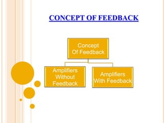
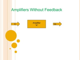
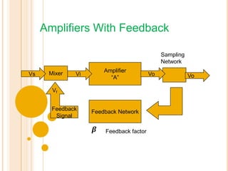
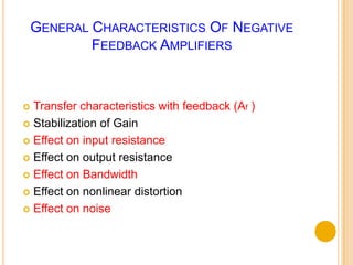
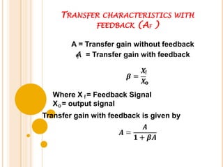
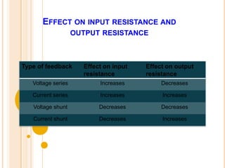
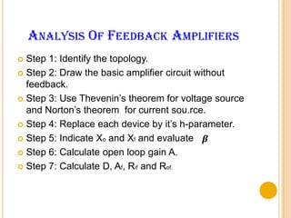
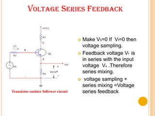
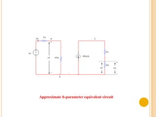
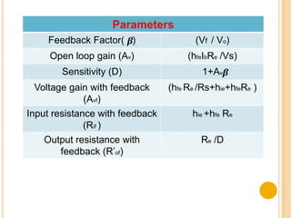
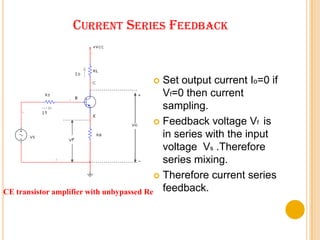
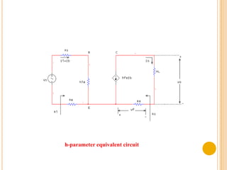
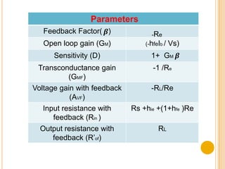
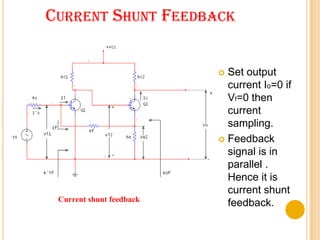
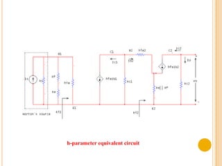
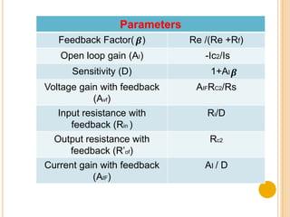
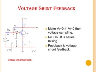
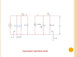


This document covers negative feedback amplifiers, including the concept of feedback, different feedback topologies, and analysis of feedback amplifiers. It discusses four main feedback topologies: voltage series, voltage shunt, current series, and current shunt. For each topology, it explains the feedback mechanism, provides an approximate h-parameter equivalent circuit, and analyzes how feedback affects characteristics like gain, input and output resistance, bandwidth, and distortion. The document is intended to guide students through key topics relating to negative feedback amplifiers.


