Downloaded 1,662 times


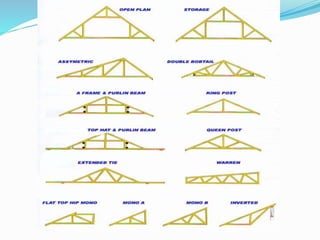


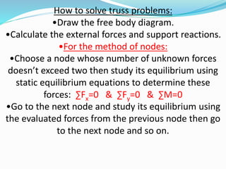
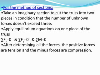
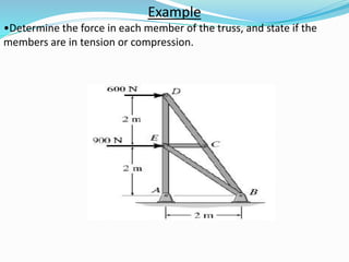


Trusses are structures composed of straight members connected at joints. They have three key characteristics: they only experience axial loads, loads are applied only at end points, and members are joined by pins. Trusses are used to support roofs and bridges. To analyze a truss, assumptions are made that loads act only at end points, member weight is ignored, and members experience only axial loads as either tension or compression. The method of joints and method of sections can be used to calculate the internal forces in each member and determine if each member is in tension or compression.


![Lecture truss [compatibility mode]](https://cdn.slidesharecdn.com/ss_thumbnails/lecturetrusscompatibilitymode-160126134009-thumbnail.jpg?width=640&height=640&fit=bounds)


