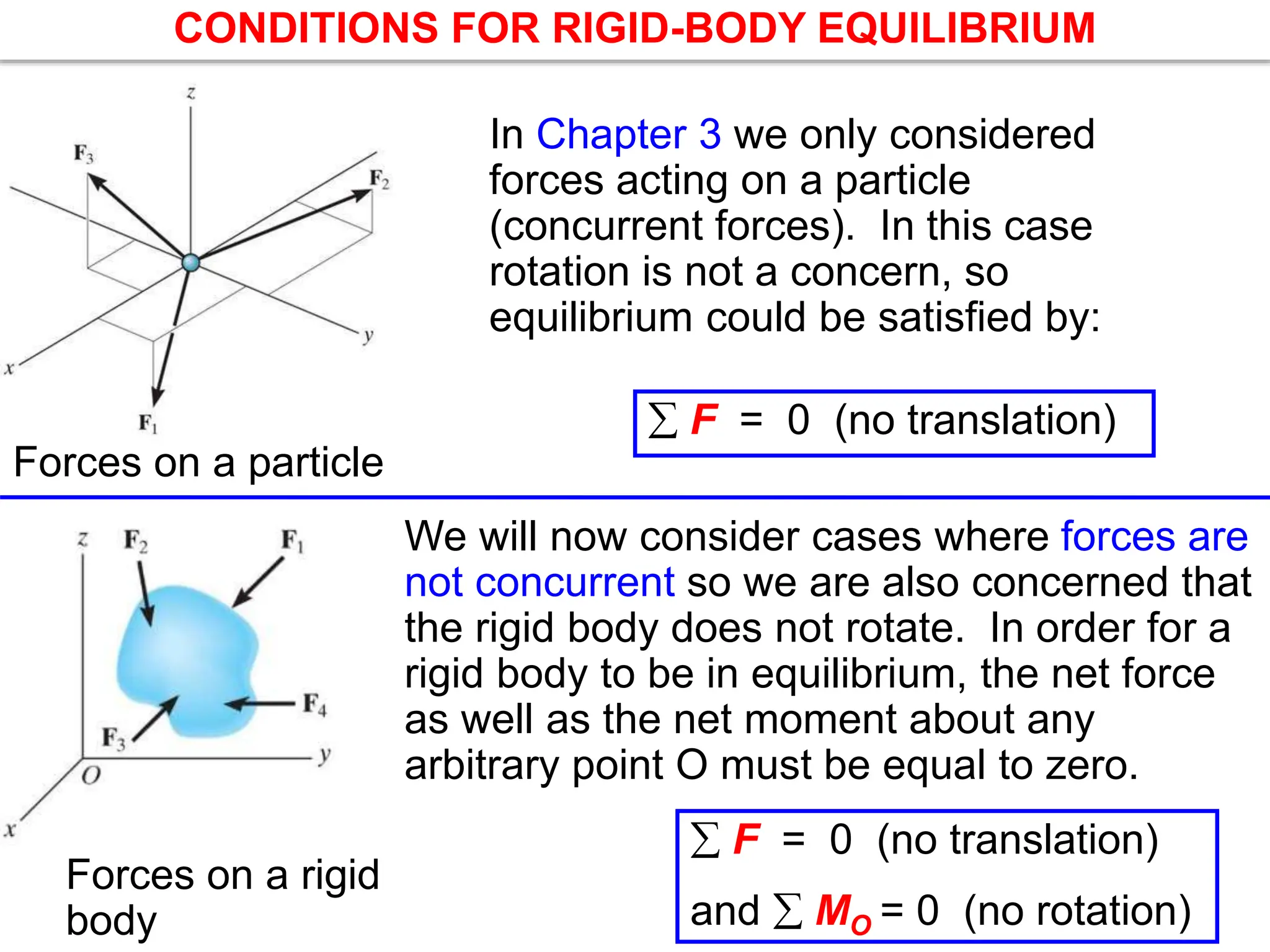
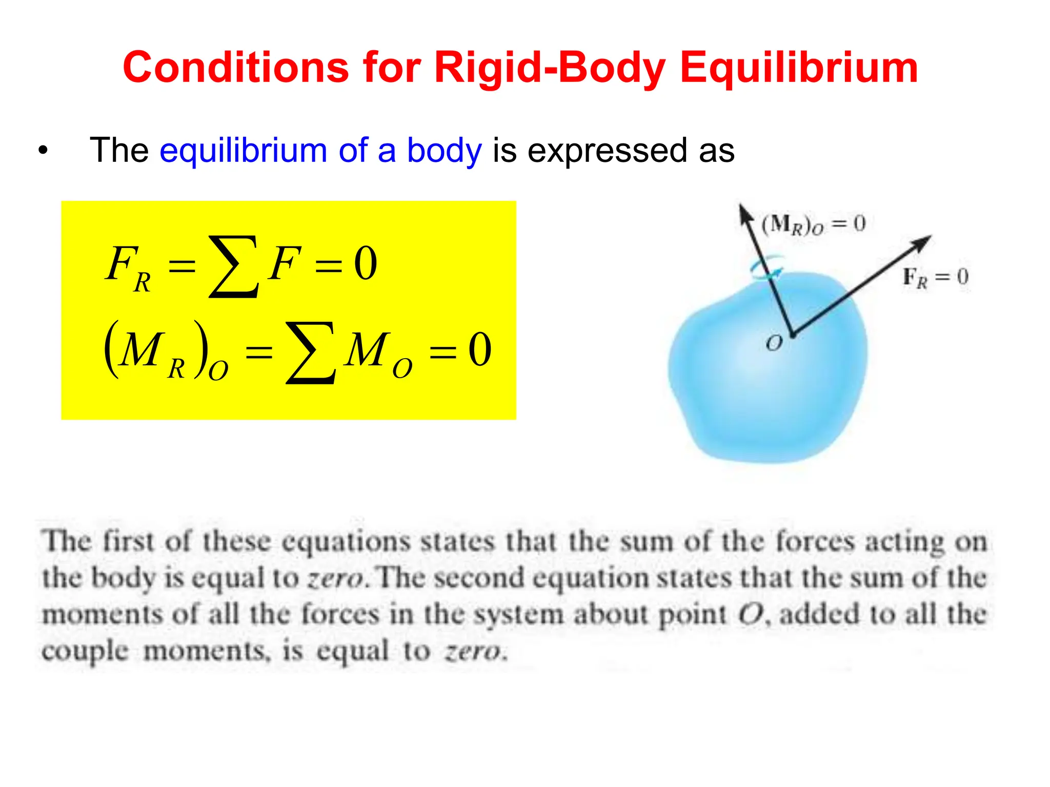
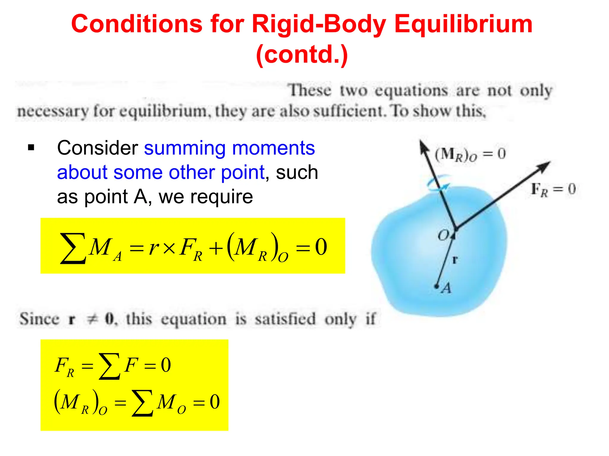
ME 1204: Engineering Statics
Dr. Faraz Junejo
Objectives
• Develop the equations of equilibrium for a rigid
body
• Concept of the free-body diagram for a rigid
body
• Solve rigid-body equilibrium problems using
the equations of equilibrium
Outline
1. Concept of Rigid Body
2. Conditions for Rigid Equilibrium
3. Free-Body Diagrams
4. Equations of Equilibrium
Rigid Body
 A rigid body can be considered as a combination of a
large number of particles in which all particles remain at
a fixed distance from one another, both before and after
applying a load.
 This model is important as material properties of any
body that is assumed to be rigid will not have to be
considered when studying the effects of forces acting on
the body.
Rigid Body (contd.)
 Statics deals primarily with the calculation of external
forces which act on rigid bodies in equilibrium.
 Determination of the internal deformations belongs to the
study of the mechanics of deformable bodies, which
normally follows statics in the curriculum i.e. Mechanics
or Strength of materials course.
CONDITIONS FOR RIGID-BODY EQUILIBRIUM
In Chapter 3 we only considered
forces acting on a particle
(concurrent forces). In this case
rotation is not a concern, so
equilibrium could be satisfied by:
Forces on a particle
We will now consider cases where forces are
not concurrent so we are also concerned that
the rigid body does not rotate. In order for a
rigid body to be in equilibrium, the net force
as well as the net moment about any
arbitrary point O must be equal to zero.
Forces on a rigid
body
 F = 0 (no translation)
and  MO = 0 (no rotation)
 F = 0 (no translation)
Conditions for Rigid-Body Equilibrium
• The equilibrium of a body is expressed as
  





0
0
O
O
R
R
M
M
F
F
Conditions for Rigid-Body Equilibrium
(contd.)
 Consider summing moments
about some other point, such
as point A, we require
 
 


 0
O
R
R
A M
F
r
M
  





0
0
O
O
R
R
M
M
F
F
Free Body Diagrams
Support Reactions
• If a support prevents the translation of a body
in a given direction, then a force is developed
on the body in that direction.
• If rotation is prevented, a couple moment is
exerted on the body.
Support Reactions (contd.)
Summary: Support Reactions
• A reaction is a force with known line of action, or a force
of unknown direction, or a moment.
• The line of action of the force or direction of the moment
is directly related to the motion that is prevented.
Recognizing support unknowns in FBD’s
Support Reactions in 2D (Table 5-1)
The 2D reactions shown below are the ones shown in Table 5-1 in
the text. As a general rule:
1) if a support prevents translation of a body in a given
direction, then a force is developed on the body in the opposite
direction.
2) if rotation is prevented, a couple moment is exerted on the
body in the opposite direction
memorize this table!
Free Body Diagrams (contd.)
Internal Forces
• External and internal forces can act on a rigid body
In summary:
• For FBD, internal forces act between adjacent particles which are
contained within the boundary of the FBD, are not represented
• Particles outside this boundary exert external forces on the
system
Internal Forces (contd.)
Free Body Diagrams (contd.)
Weight and Center of Gravity
• Each particle has a specified weight
• System can be represented by a single resultant force,
known as weight W of the body
• Location of the force application is known as the
center of gravity
Procedure for Drawing a FBD
1. Draw Outlined Shape
• Imagine body to be isolated or cut free from its
constraints
• Draw outline shape
2. Show All Forces and Couple Moments
• Identify all external forces and couple moments that
act on the body
3. Identify Each Loading and Give Dimensions
• Indicate dimensions for calculation of forces
• Known forces and couple moments should be properly
labeled with their magnitudes and directions
Procedure for Drawing a FBD (contd.)
Example: 1
Draw the free-body diagram of the uniform beam. The
beam has a mass of 100kg.
Example: 1 (contd.)
Free-Body Diagram
Free-Body Diagram’s Description
• Support at A is a fixed wall, the wall exerts three reactions
on the beam. These three forces acting on the beam at A
denoted as Ax, Ay, Az, drawn in an arbitrary direction
• Unknown magnitudes of these vectors
• Assume sense of these vectors
• For uniform beam,
Weight, W = 100(9.81) = 981N
acting through beam’s center of gravity, 3m from A
Example: 1 (contd.)
EXAMPLE: 2
“Smooth pin”
“Weightless link” (see Table 5-1)
Given: The operator applies a vertical
force to the pedal so that the
spring is stretched 1.5 in. and the
force in the short link at B is
20 lb.
Draw: A an idealized model and free-
body diagram of the foot pedal.
Free-Body Diagram’s Description
Example: 2 (contd.)
Exercise: 1
Draw a FBD of member ABC, which is supported by a smooth
collar at A, rocker at B, and link CD.
Equations of Equilibrium
• For equilibrium of a rigid body in 2D,
∑Fx = 0; ∑Fy = 0; ∑MO = 0
• ∑Fx and ∑Fy represent sums of x and y components of
all the forces
• ∑MO represents the sum of the couple moments and
moments of the force components
Procedure for Analysis
Free-Body Diagram
• Force or couple moment having an unknown magnitude
but known line of action can be assumed
• Indicate the dimensions of the body necessary for
computing the moments of forces
Equations of Equilibrium
• Apply ∑MO = 0 about a point O, that lies at the
intersection of the lines of action of two unknown
forces.
• In this way, moments of these unknowns are zero
about O and a direct solution for the third unknown can
be obtained
Procedure for Analysis (contd.)
Equations of Equilibrium
• When applying the force equilibrium equations, orient
the x and y axes along the lines that will provide the
simplest resolution of the forces into their x and y
components
• Negative result implies scalar for a force or couple
moment magnitude is opposite to that was assumed on
the FBD
Procedure for Analysis (contd.)
Example: 1
Determine the horizontal and vertical components of reaction
on the beam caused by the pin at B and the rocker at A.
Neglect the weight of the beam in the calculations.
Free Body Diagram
• 600N represented by x and y components
• 200N force acts on the beam at B
Example: 1 (contd.)
Equations of Equilibrium
N
B
B
N
F x
x
x 424
0
45
cos
600
;
0 






 
N
B
B
N
N
N
N
F
N
A
m
A
m
N
m
N
m
N
M
y
y
y
y
y
B
405
0
200
100
45
sin
600
319
;
0
319
0
)
7
(
)
2
.
0
)(
45
cos
600
(
)
5
)(
45
sin
600
(
)
2
(
100
;
0




















Example: 1 (contd.)
Example: 2
Example: 2 (contd.)
Example: 2 (contd.)
Two- Force Members
• When a member is subject to no couple moments and
forces are applied at only two points on a member, the
member is called a two-force member.
• Only force magnitude must be determined
Two- Force Members (contd.)
EXAMPLE OF TWO-FORCE MEMBERS
In the cases above, members AB can be considered as two-
force members, provided that their weight is neglected.
This fact simplifies the equilibrium analysis of some rigid
bodies since the directions of the resultant forces at A and B
are thus known (along the line joining points A and B).
Three-Force Members
• When subjected to three forces, the forces are concurrent
or parallel
Example: 1
The lever ABC is pin-supported at A and connected to a
short link BD. If the weight of the members are negligible,
determine the force of the pin on the lever at A.
Example: 1 (contd.)
Free Body Diagrams
• BD is a two-force member
• Lever ABC is a three-force member
Equations of Equilibrium
Solving,
kN
F
kN
FA
32
.
1
07
.
1


0
45
sin
3
.
60
sin
;
0
0
400
45
cos
3
.
60
cos
;
0
3
.
60
4
.
0
7
.
0
tan 1




















 





F
F
F
N
F
F
F
A
y
A
x

A man raises a 10 kg joist, of
length 4 m, by pulling on a
rope.
Find the tension in the rope
and the reaction at A.
SOLUTION:
• Create a free-body diagram of the joist.
Note that the joist is a 3 force body
acted upon by the rope, its weight, and
the reaction at A.
• The three forces must be concurrent
for static equilibrium. Therefore, the
reaction R must pass through the
intersection of the lines of action of the
weight and rope forces. Determine the
direction of the reaction force R.
• Utilize a force triangle to determine
the magnitude of the reaction force R.
Example: 2
• Create a free-body diagram of the joist.
• Determine the direction of the reaction
force R.
 
 
 
636
.
1
414
.
1
313
.
2
tan
m
2.313
m
515
.
0
828
.
2
m
515
.
0
20
tan
m
414
.
1
)
20
45
cot(
m
414
.
1
m
828
.
2
45
cos
m
4
45
cos
2
1


















AE
CE
BD
BF
CE
CD
BD
AF
AE
CD
AB
AF


6
.
58


Example: 2 (contd.)
• Determine the magnitude of the reaction
force R.



38.6
sin
N
1
.
98
110
sin
4
.
31
sin


R
T
N
8
.
147
N
9
.
81


R
T
Example: 2 (contd.)
Exercises
 Engineering Mechanics - Statics, R.C. Hibbeler, 12th
Edition
• Q5.11 – Q5.24
• Q5.32 – Q5.37
• Q5.41 – Q5.45
QUIZ
1. If a support prevents translation of a body, then the
support exerts a ___________ on the body.
A) Couple moment
B) Force
C) Both A and B.
D) None of the above
2. Internal forces are _________ shown on the free body
diagram of a whole body.
A) Always
B) Often
C) Rarely
D) Never
QUIZ (contd.)
3. The beam and the cable (with a frictionless pulley at D)
support an 80 kg load at C. In a FBD of only the
beam, there are how many unknowns?
A) 2 forces and 1 couple moment
B) 3 forces and 1 couple moment
C) 3 forces
D) 4 forces
QUIZ (contd.)
4. Internal forces are not shown on a free-body diagram
because the internal forces are_____.
A) Equal to zero
B) Equal and opposite and they do not affect the
calculations
C) Negligibly small
D) Not important
QUIZ (contd.)
5. The three scalar equations  FX =  FY =  MO = 0,
are ____ equations of equilibrium in two dimensions.
A) Incorrect B) The only correct
C) The most commonly used D) Not sufficient
6. A rigid body is subjected to forces.
This body can be considered
as a ______ member.
A) Single-force B) Two-force
C) Three-force D) Six-force

Engineering Mechanics Chapter 5 Equilibrium of a Rigid Body

  • 1.
    ME 1204: EngineeringStatics Dr. Faraz Junejo
  • 2.
    Objectives • Develop theequations of equilibrium for a rigid body • Concept of the free-body diagram for a rigid body • Solve rigid-body equilibrium problems using the equations of equilibrium
  • 3.
    Outline 1. Concept ofRigid Body 2. Conditions for Rigid Equilibrium 3. Free-Body Diagrams 4. Equations of Equilibrium
  • 4.
    Rigid Body  Arigid body can be considered as a combination of a large number of particles in which all particles remain at a fixed distance from one another, both before and after applying a load.  This model is important as material properties of any body that is assumed to be rigid will not have to be considered when studying the effects of forces acting on the body.
  • 5.
    Rigid Body (contd.) Statics deals primarily with the calculation of external forces which act on rigid bodies in equilibrium.  Determination of the internal deformations belongs to the study of the mechanics of deformable bodies, which normally follows statics in the curriculum i.e. Mechanics or Strength of materials course.
  • 6.
    CONDITIONS FOR RIGID-BODYEQUILIBRIUM In Chapter 3 we only considered forces acting on a particle (concurrent forces). In this case rotation is not a concern, so equilibrium could be satisfied by: Forces on a particle We will now consider cases where forces are not concurrent so we are also concerned that the rigid body does not rotate. In order for a rigid body to be in equilibrium, the net force as well as the net moment about any arbitrary point O must be equal to zero. Forces on a rigid body  F = 0 (no translation) and  MO = 0 (no rotation)  F = 0 (no translation)
  • 7.
    Conditions for Rigid-BodyEquilibrium • The equilibrium of a body is expressed as         0 0 O O R R M M F F
  • 8.
    Conditions for Rigid-BodyEquilibrium (contd.)  Consider summing moments about some other point, such as point A, we require        0 O R R A M F r M         0 0 O O R R M M F F
  • 9.
    Free Body Diagrams SupportReactions • If a support prevents the translation of a body in a given direction, then a force is developed on the body in that direction. • If rotation is prevented, a couple moment is exerted on the body.
  • 10.
  • 11.
  • 12.
  • 13.
    Summary: Support Reactions •A reaction is a force with known line of action, or a force of unknown direction, or a moment. • The line of action of the force or direction of the moment is directly related to the motion that is prevented.
  • 14.
  • 15.
    Support Reactions in2D (Table 5-1) The 2D reactions shown below are the ones shown in Table 5-1 in the text. As a general rule: 1) if a support prevents translation of a body in a given direction, then a force is developed on the body in the opposite direction. 2) if rotation is prevented, a couple moment is exerted on the body in the opposite direction memorize this table!
  • 18.
    Free Body Diagrams(contd.) Internal Forces • External and internal forces can act on a rigid body In summary: • For FBD, internal forces act between adjacent particles which are contained within the boundary of the FBD, are not represented • Particles outside this boundary exert external forces on the system
  • 19.
  • 20.
    Free Body Diagrams(contd.) Weight and Center of Gravity • Each particle has a specified weight • System can be represented by a single resultant force, known as weight W of the body • Location of the force application is known as the center of gravity
  • 21.
    Procedure for Drawinga FBD 1. Draw Outlined Shape • Imagine body to be isolated or cut free from its constraints • Draw outline shape 2. Show All Forces and Couple Moments • Identify all external forces and couple moments that act on the body
  • 22.
    3. Identify EachLoading and Give Dimensions • Indicate dimensions for calculation of forces • Known forces and couple moments should be properly labeled with their magnitudes and directions Procedure for Drawing a FBD (contd.)
  • 23.
    Example: 1 Draw thefree-body diagram of the uniform beam. The beam has a mass of 100kg.
  • 24.
  • 25.
    Free-Body Diagram’s Description •Support at A is a fixed wall, the wall exerts three reactions on the beam. These three forces acting on the beam at A denoted as Ax, Ay, Az, drawn in an arbitrary direction • Unknown magnitudes of these vectors • Assume sense of these vectors • For uniform beam, Weight, W = 100(9.81) = 981N acting through beam’s center of gravity, 3m from A Example: 1 (contd.)
  • 26.
    EXAMPLE: 2 “Smooth pin” “Weightlesslink” (see Table 5-1) Given: The operator applies a vertical force to the pedal so that the spring is stretched 1.5 in. and the force in the short link at B is 20 lb. Draw: A an idealized model and free- body diagram of the foot pedal.
  • 27.
  • 28.
    Exercise: 1 Draw aFBD of member ABC, which is supported by a smooth collar at A, rocker at B, and link CD.
  • 29.
    Equations of Equilibrium •For equilibrium of a rigid body in 2D, ∑Fx = 0; ∑Fy = 0; ∑MO = 0 • ∑Fx and ∑Fy represent sums of x and y components of all the forces • ∑MO represents the sum of the couple moments and moments of the force components
  • 30.
    Procedure for Analysis Free-BodyDiagram • Force or couple moment having an unknown magnitude but known line of action can be assumed • Indicate the dimensions of the body necessary for computing the moments of forces
  • 31.
    Equations of Equilibrium •Apply ∑MO = 0 about a point O, that lies at the intersection of the lines of action of two unknown forces. • In this way, moments of these unknowns are zero about O and a direct solution for the third unknown can be obtained Procedure for Analysis (contd.)
  • 32.
    Equations of Equilibrium •When applying the force equilibrium equations, orient the x and y axes along the lines that will provide the simplest resolution of the forces into their x and y components • Negative result implies scalar for a force or couple moment magnitude is opposite to that was assumed on the FBD Procedure for Analysis (contd.)
  • 33.
    Example: 1 Determine thehorizontal and vertical components of reaction on the beam caused by the pin at B and the rocker at A. Neglect the weight of the beam in the calculations.
  • 34.
    Free Body Diagram •600N represented by x and y components • 200N force acts on the beam at B Example: 1 (contd.)
  • 35.
    Equations of Equilibrium N B B N Fx x x 424 0 45 cos 600 ; 0          N B B N N N N F N A m A m N m N m N M y y y y y B 405 0 200 100 45 sin 600 319 ; 0 319 0 ) 7 ( ) 2 . 0 )( 45 cos 600 ( ) 5 )( 45 sin 600 ( ) 2 ( 100 ; 0                     Example: 1 (contd.)
  • 36.
  • 37.
  • 38.
  • 39.
    Two- Force Members •When a member is subject to no couple moments and forces are applied at only two points on a member, the member is called a two-force member. • Only force magnitude must be determined
  • 40.
  • 41.
    EXAMPLE OF TWO-FORCEMEMBERS In the cases above, members AB can be considered as two- force members, provided that their weight is neglected. This fact simplifies the equilibrium analysis of some rigid bodies since the directions of the resultant forces at A and B are thus known (along the line joining points A and B).
  • 42.
    Three-Force Members • Whensubjected to three forces, the forces are concurrent or parallel
  • 43.
    Example: 1 The leverABC is pin-supported at A and connected to a short link BD. If the weight of the members are negligible, determine the force of the pin on the lever at A.
  • 44.
    Example: 1 (contd.) FreeBody Diagrams • BD is a two-force member • Lever ABC is a three-force member Equations of Equilibrium Solving, kN F kN FA 32 . 1 07 . 1   0 45 sin 3 . 60 sin ; 0 0 400 45 cos 3 . 60 cos ; 0 3 . 60 4 . 0 7 . 0 tan 1                            F F F N F F F A y A x 
  • 45.
    A man raisesa 10 kg joist, of length 4 m, by pulling on a rope. Find the tension in the rope and the reaction at A. SOLUTION: • Create a free-body diagram of the joist. Note that the joist is a 3 force body acted upon by the rope, its weight, and the reaction at A. • The three forces must be concurrent for static equilibrium. Therefore, the reaction R must pass through the intersection of the lines of action of the weight and rope forces. Determine the direction of the reaction force R. • Utilize a force triangle to determine the magnitude of the reaction force R. Example: 2
  • 46.
    • Create afree-body diagram of the joist. • Determine the direction of the reaction force R.       636 . 1 414 . 1 313 . 2 tan m 2.313 m 515 . 0 828 . 2 m 515 . 0 20 tan m 414 . 1 ) 20 45 cot( m 414 . 1 m 828 . 2 45 cos m 4 45 cos 2 1                   AE CE BD BF CE CD BD AF AE CD AB AF   6 . 58   Example: 2 (contd.)
  • 47.
    • Determine themagnitude of the reaction force R.    38.6 sin N 1 . 98 110 sin 4 . 31 sin   R T N 8 . 147 N 9 . 81   R T Example: 2 (contd.)
  • 48.
    Exercises  Engineering Mechanics- Statics, R.C. Hibbeler, 12th Edition • Q5.11 – Q5.24 • Q5.32 – Q5.37 • Q5.41 – Q5.45
  • 49.
    QUIZ 1. If asupport prevents translation of a body, then the support exerts a ___________ on the body. A) Couple moment B) Force C) Both A and B. D) None of the above 2. Internal forces are _________ shown on the free body diagram of a whole body. A) Always B) Often C) Rarely D) Never
  • 50.
    QUIZ (contd.) 3. Thebeam and the cable (with a frictionless pulley at D) support an 80 kg load at C. In a FBD of only the beam, there are how many unknowns? A) 2 forces and 1 couple moment B) 3 forces and 1 couple moment C) 3 forces D) 4 forces
  • 51.
    QUIZ (contd.) 4. Internalforces are not shown on a free-body diagram because the internal forces are_____. A) Equal to zero B) Equal and opposite and they do not affect the calculations C) Negligibly small D) Not important
  • 52.
    QUIZ (contd.) 5. Thethree scalar equations  FX =  FY =  MO = 0, are ____ equations of equilibrium in two dimensions. A) Incorrect B) The only correct C) The most commonly used D) Not sufficient 6. A rigid body is subjected to forces. This body can be considered as a ______ member. A) Single-force B) Two-force C) Three-force D) Six-force