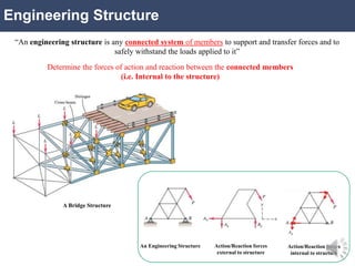
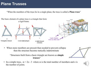
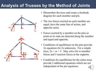
ENGINEERING STATICS
Session 2020
Chapter
4 Structures:
Plane Trusses
Engineering Structure
“An engineering structure is any connected system of members to support and transfer forces and to
safely withstand the loads applied to it”
Determine the forces of action and reaction between the connected members
(i.e. Internal to the structure)
Action/Reaction forces
internal to structure
Action/Reaction forces
external to structure
An Engineering Structure
A Bridge Structure
Trusses
“A framework composed of members joined at their ends to form a rigid structure is called a truss”
Roof support
truss
Derricks truss
Bridge truss
Channel
beam
Angles
I-beams
Welded Joint Rivet Joint Nut/Bolt
Joint
Plane Trusses
“When the members of the truss lie in a single plane, the truss is called a Plane truss”
A pair of plane
truss on either side.
The basic element of a plane truss is a triangle that form
a rigid frame.
Triangular element A non-rigid polygon A rigid element
extension
• When more members are present than needed to prevent collapse
then the structure become statically indeterminate
“Structures built from a basic triangle are known as simple
trusses”
• In a simple truss, m = 2n - 3 where m is the total number of members and n is
the number of joints.
Analysis of Trusses by the Method of Joints
• Dismember the truss and create a freebody
diagram for each member and pin.
• The two forces exerted on each member are
equal, have the same line of action, and
opposite sense.
• Forces exerted by a member on the pins or
joints at its ends are directed along the member
and equal and opposite.
• Conditions of equilibrium on the pins provide
2n equations for 2n unknowns. For a simple
truss, 2n = m + 3. May solve for m member
forces and 3 reaction forces at the supports.
• Conditions for equilibrium for the entire truss
provide 3 additional equations which are not
independent of the pin equations.
Sample Problem 4.1
Using the method of joints, determine
the force in each member of the truss.
SOLUTION:
• Based on a free-body diagram of the
entire truss, solve the 3 equilibrium
equations for the reactions at E and C.
• Joint A is subjected to only two unknown
member forces. Determine these from the
joint equilibrium requirements.
• In succession, determine unknown
member forces at joints D, B, and E from
joint equilibrium requirements.
• All member forces and support reactions
are known at joint C. However, the joint
equilibrium requirements may be applied
to check the results.
Sample Problem 4.1
SOLUTION:
• Based on a free-body diagram of the entire truss,
solve the 3 equilibrium equations for the reactions
at E and C.
       
ft
6
ft
12
lb
1000
ft
24
lb
2000
0
E
MC






 lb
000
,
10
E
 
 x
x C
F 0 0

x
C
 



 y
y C
F lb
10,000
lb
1000
-
lb
2000
0

 lb
7000
y
C
Sample Problem 4.1
• Joint A is subjected to only two unknown
member forces. Determine these from the
joint equilibrium requirements.
5
3
4
lb
2000 AD
AB F
F


C
F
T
F
AD
AB
lb
2500
lb
1500


• There are now only two unknown member
forces at joint D.
  DA
DE
DA
DB
F
F
F
F
5
3
2


C
F
T
F
DE
DB
lb
3000
lb
2500


Sample Problem 4.1
• All member forces and support reactions are
known at joint C. However, the joint equilibrium
requirements may be applied to check the results.
   
   
checks
0
8750
7000
checks
0
8750
5250
5
4
5
3










y
x
F
F
Analysis of Trusses by the Method of Sections
• When the force in only one member or the
forces in a very few members are desired, the
method of sections works well.
• To determine the force in member BD, pass a
section through the truss as shown and create
a free body diagram for the left side.
• With only three members cut by the section,
the equations for static equilibrium may be
applied to determine the unknown member
forces, including FBD.
Sample Problem 4.2
SOLUTION:
• Take the entire truss as a free body.
Apply the conditions for static equilib-
rium to solve for the reactions at A and L.
𝑀𝐴 = 0 = − 5 m 6 kN − 10 m 6 kN − 15 m 6 kN
− 20 m 1 kN − 25 m 1 kN + 30 m 𝐿
𝐿 = 7.5 kN ↑
𝐹
𝑦 = 0 = −20 kN + 𝐿 + 𝐴
𝐴 = 12.5 kN ↑
Sample Problem 4.2
• Pass a section through members FH, GH, and GI
and take the right-hand section as a free body.
       
kN
13
.
13
0
m
33
.
5
m
5
kN
1
m
10
kN
7.50
0







GI
GI
H
F
F
M
• Apply the conditions for static equilibrium to
determine the desired member forces.
T
FGI kN
13
.
13

Sample Problem 4.2
        
  
kN
82
.
13
0
m
8
cos
m
5
kN
1
m
10
kN
1
m
15
kN
7.5
0
07
.
28
5333
.
0
m
15
m
8
tan













FH
FH
G
F
F
M
GL
FG



C
FFH kN
82
.
13

 
        
kN
371
.
1
0
m
10
cos
m
5
kN
1
m
10
kN
1
0
15
.
43
9375
.
0
m
8
m
5
tan
3
2












GH
GH
L
F
F
M
HI
GI



C
FGH kN
371
.
1


Chapter 4_Engineering Structures_Review.pptx

  • 1.
  • 2.
    Engineering Structure “An engineeringstructure is any connected system of members to support and transfer forces and to safely withstand the loads applied to it” Determine the forces of action and reaction between the connected members (i.e. Internal to the structure) Action/Reaction forces internal to structure Action/Reaction forces external to structure An Engineering Structure A Bridge Structure
  • 3.
    Trusses “A framework composedof members joined at their ends to form a rigid structure is called a truss” Roof support truss Derricks truss Bridge truss Channel beam Angles I-beams Welded Joint Rivet Joint Nut/Bolt Joint
  • 4.
    Plane Trusses “When themembers of the truss lie in a single plane, the truss is called a Plane truss” A pair of plane truss on either side. The basic element of a plane truss is a triangle that form a rigid frame. Triangular element A non-rigid polygon A rigid element extension • When more members are present than needed to prevent collapse then the structure become statically indeterminate “Structures built from a basic triangle are known as simple trusses” • In a simple truss, m = 2n - 3 where m is the total number of members and n is the number of joints.
  • 5.
    Analysis of Trussesby the Method of Joints • Dismember the truss and create a freebody diagram for each member and pin. • The two forces exerted on each member are equal, have the same line of action, and opposite sense. • Forces exerted by a member on the pins or joints at its ends are directed along the member and equal and opposite. • Conditions of equilibrium on the pins provide 2n equations for 2n unknowns. For a simple truss, 2n = m + 3. May solve for m member forces and 3 reaction forces at the supports. • Conditions for equilibrium for the entire truss provide 3 additional equations which are not independent of the pin equations.
  • 6.
    Sample Problem 4.1 Usingthe method of joints, determine the force in each member of the truss. SOLUTION: • Based on a free-body diagram of the entire truss, solve the 3 equilibrium equations for the reactions at E and C. • Joint A is subjected to only two unknown member forces. Determine these from the joint equilibrium requirements. • In succession, determine unknown member forces at joints D, B, and E from joint equilibrium requirements. • All member forces and support reactions are known at joint C. However, the joint equilibrium requirements may be applied to check the results.
  • 7.
    Sample Problem 4.1 SOLUTION: •Based on a free-body diagram of the entire truss, solve the 3 equilibrium equations for the reactions at E and C.         ft 6 ft 12 lb 1000 ft 24 lb 2000 0 E MC        lb 000 , 10 E    x x C F 0 0  x C       y y C F lb 10,000 lb 1000 - lb 2000 0   lb 7000 y C
  • 8.
    Sample Problem 4.1 •Joint A is subjected to only two unknown member forces. Determine these from the joint equilibrium requirements. 5 3 4 lb 2000 AD AB F F   C F T F AD AB lb 2500 lb 1500   • There are now only two unknown member forces at joint D.   DA DE DA DB F F F F 5 3 2   C F T F DE DB lb 3000 lb 2500  
  • 9.
    Sample Problem 4.1 •All member forces and support reactions are known at joint C. However, the joint equilibrium requirements may be applied to check the results.         checks 0 8750 7000 checks 0 8750 5250 5 4 5 3           y x F F
  • 10.
    Analysis of Trussesby the Method of Sections • When the force in only one member or the forces in a very few members are desired, the method of sections works well. • To determine the force in member BD, pass a section through the truss as shown and create a free body diagram for the left side. • With only three members cut by the section, the equations for static equilibrium may be applied to determine the unknown member forces, including FBD.
  • 11.
    Sample Problem 4.2 SOLUTION: •Take the entire truss as a free body. Apply the conditions for static equilib- rium to solve for the reactions at A and L. 𝑀𝐴 = 0 = − 5 m 6 kN − 10 m 6 kN − 15 m 6 kN − 20 m 1 kN − 25 m 1 kN + 30 m 𝐿 𝐿 = 7.5 kN ↑ 𝐹 𝑦 = 0 = −20 kN + 𝐿 + 𝐴 𝐴 = 12.5 kN ↑
  • 12.
    Sample Problem 4.2 •Pass a section through members FH, GH, and GI and take the right-hand section as a free body.         kN 13 . 13 0 m 33 . 5 m 5 kN 1 m 10 kN 7.50 0        GI GI H F F M • Apply the conditions for static equilibrium to determine the desired member forces. T FGI kN 13 . 13 
  • 13.
    Sample Problem 4.2 •Pass a section through members FH, GH, and GI and take the right-hand section as a free body.         kN 13 . 13 0 m 33 . 5 m 5 kN 1 m 10 kN 7.50 0        GI GI H F F M • Apply the conditions for static equilibrium to determine the desired member forces. T FGI kN 13 . 13 
  • 14.
    Sample Problem 4.2 •Pass a section through members FH, GH, and GI and take the right-hand section as a free body.         kN 13 . 13 0 m 33 . 5 m 5 kN 1 m 10 kN 7.50 0        GI GI H F F M • Apply the conditions for static equilibrium to determine the desired member forces. T FGI kN 13 . 13 
  • 15.
    Sample Problem 4.2            kN 82 . 13 0 m 8 cos m 5 kN 1 m 10 kN 1 m 15 kN 7.5 0 07 . 28 5333 . 0 m 15 m 8 tan              FH FH G F F M GL FG    C FFH kN 82 . 13             kN 371 . 1 0 m 10 cos m 5 kN 1 m 10 kN 1 0 15 . 43 9375 . 0 m 8 m 5 tan 3 2             GH GH L F F M HI GI    C FGH kN 371 . 1 