Downloaded 369 times


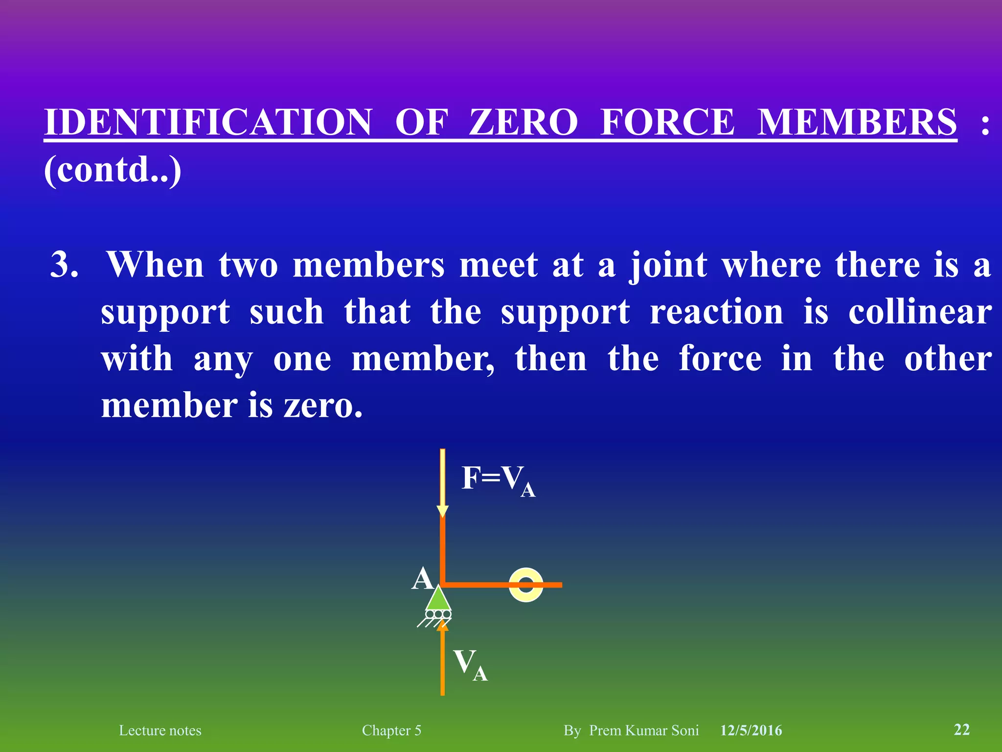


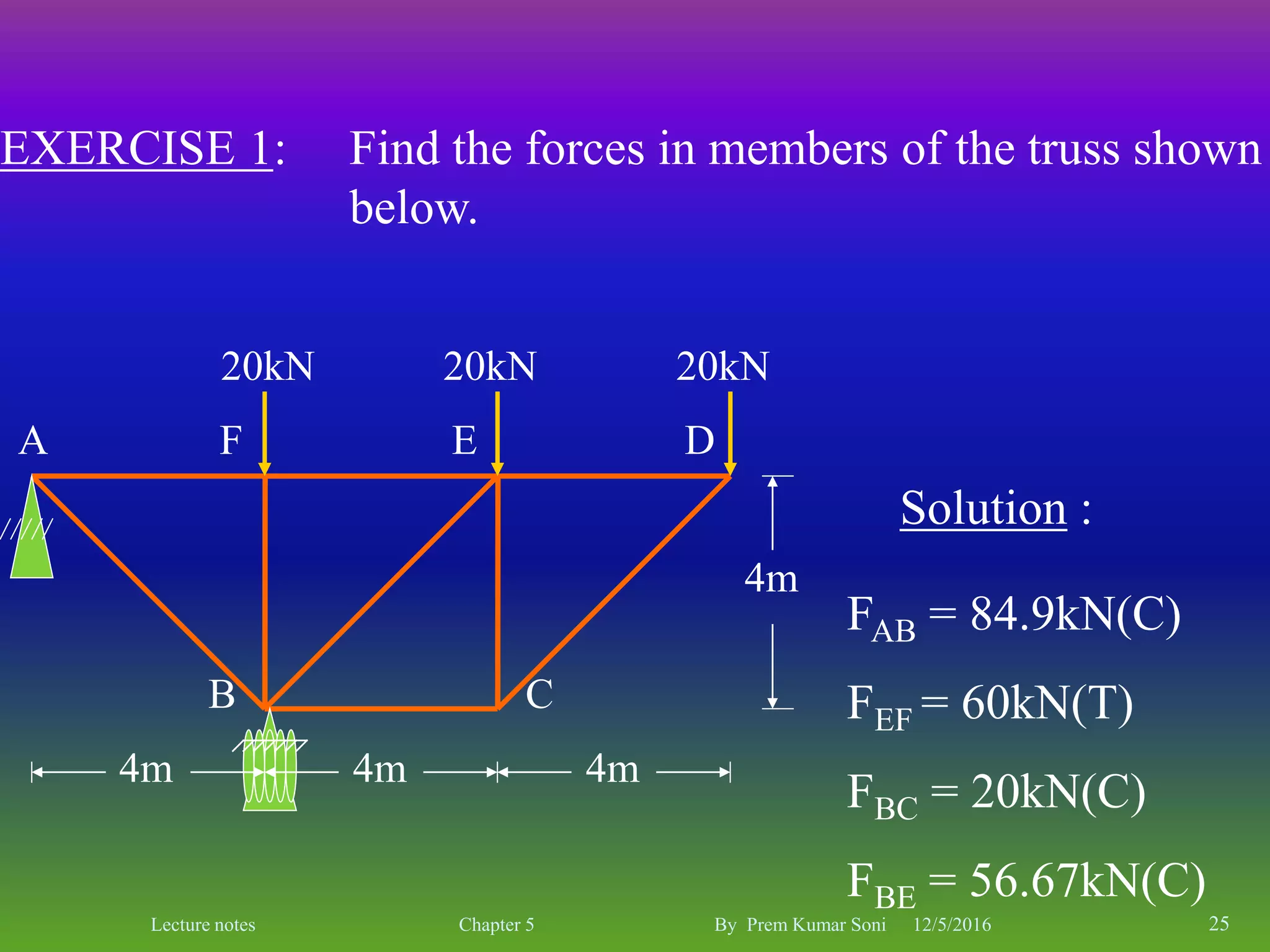
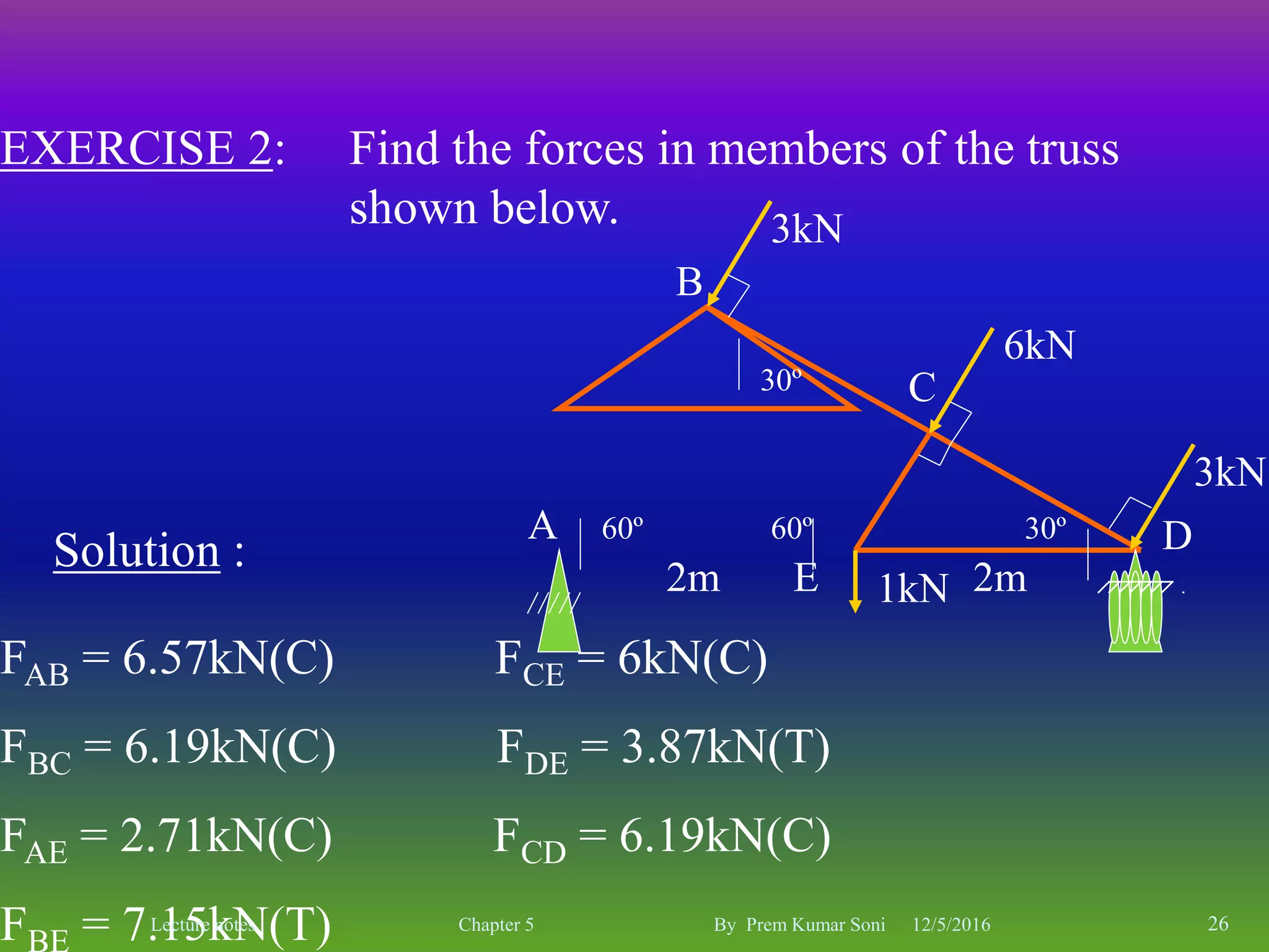
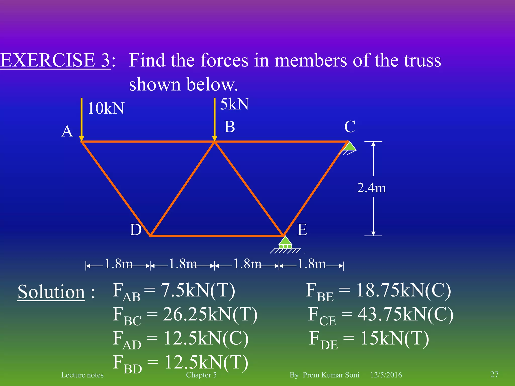

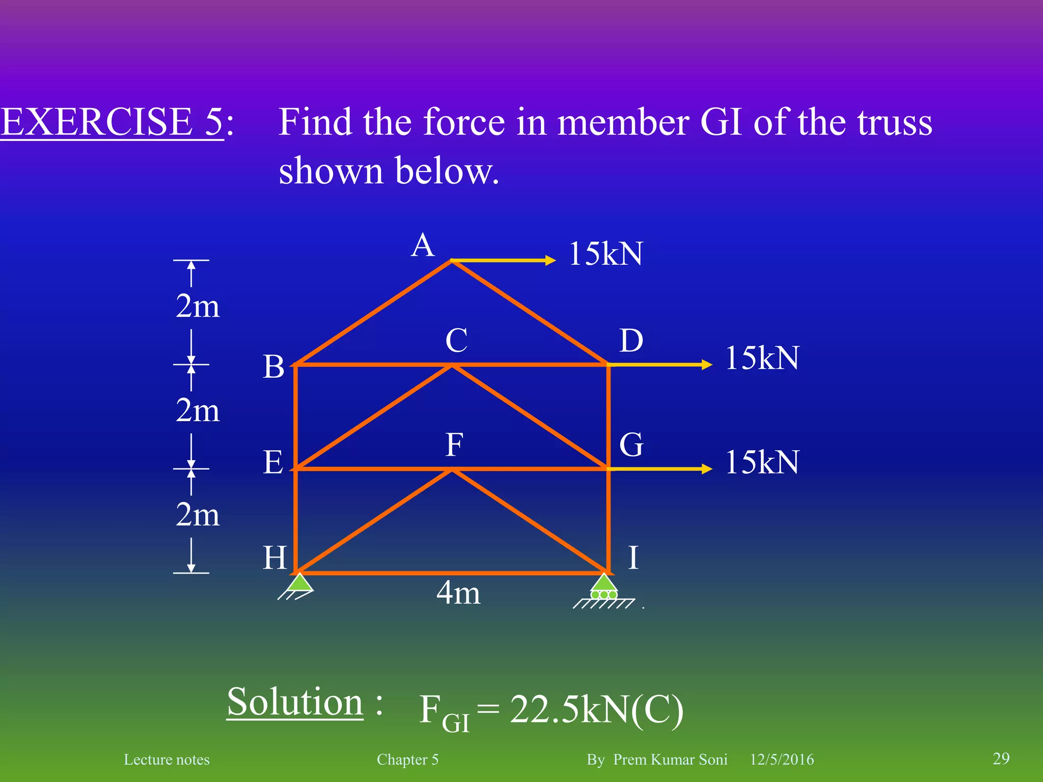
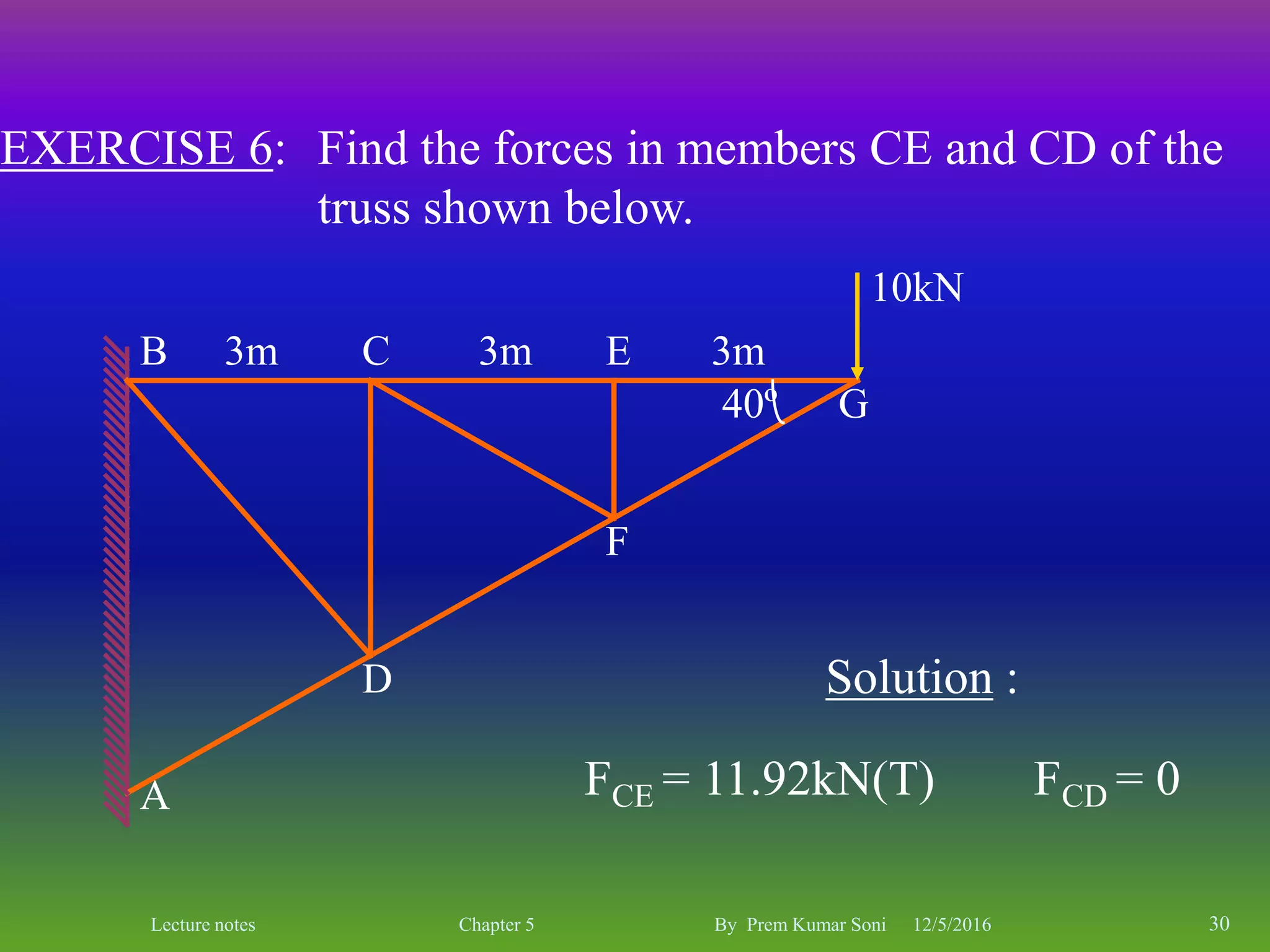

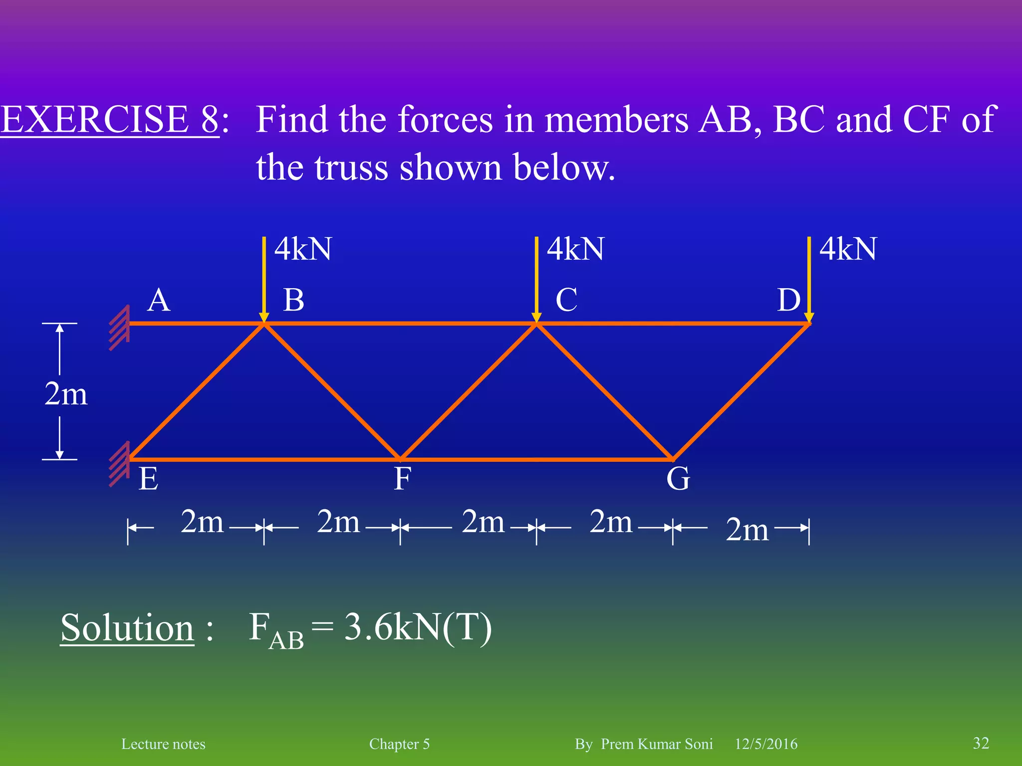


The document is a set of lecture notes by Prem Kumar Soni on the topic of trusses, covering definitions, types, and analysis methods including the method of joints and method of sections. It includes detailed information on statical determinacy, stability conditions, and practical examples of finding forces in truss members. The notes are intended for educational purposes, focusing on the principles of structural analysis in civil engineering.


![Lecture truss [compatibility mode]](https://cdn.slidesharecdn.com/ss_thumbnails/lecturetrusscompatibilitymode-160126134009-thumbnail.jpg?width=640&height=640&fit=bounds)


