Downloaded 1,041 times
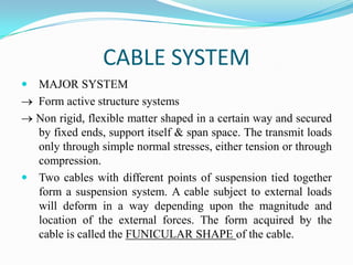
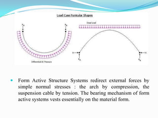
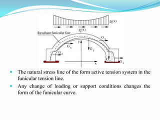
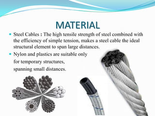
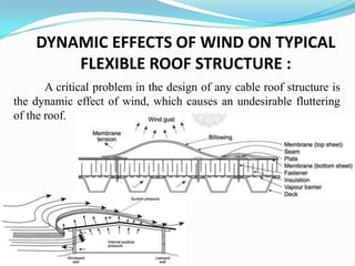
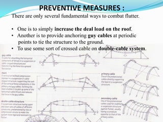
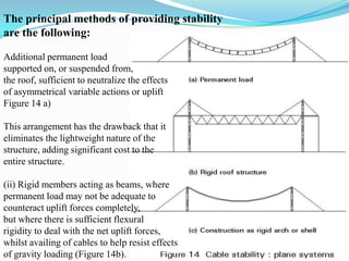
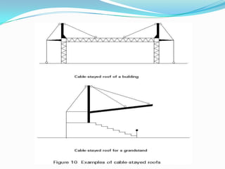
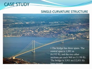
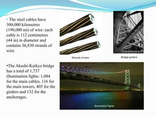

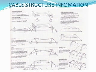

The document discusses different types of cable structures. It describes cable systems as major structural systems that redirect external forces through simple normal stresses of tension or compression. Suspension cable structures form a funicular shape to support loads. Steel cables are commonly used due to their high tensile strength to span large distances. Dynamic effects of wind can cause fluttering in flexible cable roof structures. Preventive measures include increasing dead load, adding anchoring cables, or using crossed cable systems. Case studies on the Akashi-Kaikyo Bridge and Penang Bridge demonstrate single and double cable structural designs.


